
Related Manuals for ferrotec Temescal CV-12SLX


Summary of Contents for ferrotec Temescal CV-12SLX
- Page 1 0101-8292-0 CV-12SLX USER MANUAL Revision C, April 2016 Temescal, a division of Ferrotec (USA) Corporation 4569-C Las Positas Road, Livermore, CA 94551 Tel: 1-800-522-1215; Fax: 925-449-4096...
- Page 2 1125-1 for 400-V models. Changed all occurrences of 0620-9654-0 to Pursuant to PN change implemented April 0620-9654-1 and all occurrences of 6024- by ECN 12185. 2016 6112-1 to 0620-8684-1. © 2016 Ferrotec (USA) Corporation TemEBeam is a trademark of Ferrotec Corporation.
-
Page 3: Table Of Contents
Table of Contents Page Section Number and Title Number Introduction to the CV-12SLX ..................1-1 1.1 Product Description ....................... 1-1 1.2 CV-12SLX HVPS Description and Specifications ..............1-1 1.3 Filament Power Supply Description and Specifications ............. 1-2 1.4 Miscellaneous Hardware and Interconnection Cables ............1-3 1.5 TemEBeam EBC Integrated Controller ................ - Page 4 CV-12SLX User Manual 0101-8292-0, Rev. C...
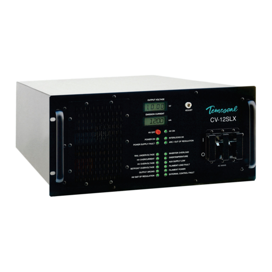
- Page 5 List of Illustrations Figure Number and Title Page Numbe Figure 1-1 CV-12SLX HVPS Front Panel ........................1-1 Figure 1-2 Filament Power Supply Front Panel ......................1-2 Figure 1-3 EBC Main Control Unit and Hand-Held Controller ..................1-3 Figure 2-1 Mounting Hole Pattern for FPS Module(s) ....................2-4 Figure 2-2 Facility Low Impedance Grounding Requirements ..................
- Page 6 List of Illustrations (Continued) Figure Number and Title Page Numbe Ishikawa Diagram #2: Interlock Fault ........................... 5-7 Ishikawa Diagram #3: No Beam After HV and Gun Are Switched ON ................5-8 Ishikawa Diagram #4: HV Output Unstable ........................5-8 Ishikawa Diagram #5: HV Out of Regulation LED Lights Frequently .................
- Page 7 Terms and Conditions 1. Delivery. Unless otherwise stated, shipments of Ferrotec Temescal Electron Beam Gun and Systems products quoted and/or produced at the Livermore, CA factory site will be made Ex-Works, Livermore, CA Incoterms. Shipping date as are approximate and are based on conditions at the time of acceptance and prompt receipt of all necessary information from the Buyer.
- Page 8 FERROTEC (USA) CORPORATION’S ACCEPTANCE OF THE REFERENCED PURCHASE ORDER IS EXPRESSLY MADE CONDITIONAL ON THE PARTY’S ASSENT (WHO SUBMITTED THE REFERENCED PURCHASE ORDER) TO FERROTEC’S ADDITIONAL OR DIFFERENT TERMS IN THIS ORDER ACKNOWLEDGEMENT. IF NO ANSWER IS RECEIVED FROM THE PARTY SUBMITTING THE REFERENCED PURCHASE ORDER WITHIN A REASONABLE TIME AFTER RECEIPT OF THIS ORDER ACKNOWLEDGEMENT, IT WILL BE ASSUMED THAT THEIR INCLUSION HAS BEEN ASSENTED TO.
- Page 9 THE TERM OF ANY WARRANTY OR WARRANTOR IMPLIED BY LAW SHALL END ON THE TERMINATION DATE OF THIS LIMITED WARRANTY SPECIFIED IN SECTION 2. B. Warranty duration for out of warranty items repaired by Ferrotec shall be ninety (90) days from date of shipment post repair “Ex-works”.
- Page 10 Safety Instructions for Operating and Service Personnel Operators and service personnel should always wear safety glasses. Operators shall not enter areas intended for service access only. Only experienced service personnel should enter such areas, and only after taking the preliminary precautions described in paragraphs 1 through 6 below.
- Page 11 Temescal, Livermore, CA, a division of Ferrotec (USA) Corp. The equipment, or any of its parts, shall not be altered without the prior written approval of Temescal. The user and/or purchaser of this equipment shall have the sole responsibility for any malfunction which results from improper use, faulty maintenance, damage, improper repair, or alteration by any party other than Temescal.
- Page 12 Guidelines And Good Practices 1. Follow applicable clean room procedures (smocks, masks, gloves, etc.). 2. Do not expose the vent and purge valves to excessive pressures. The nitrogen line regulator is factory set at 15 psi and must not be adjusted above 20 psi. 3.
-
Page 13: Introduction To The Cv-12Slx
1 Introduction to the CV-12SLX Product Description The Temescal Model CV-12SLX is a 12-kW, constant voltage, high-frequency, switching electron beam power supply. Designed to power and control up to two electron beam sources, the CV- 12SLX is compatible with sources featuring either permanent-magnet or electromagnetic deflection. -
Page 14: Filament Power Supply Description And Specifications
1.3 Filament Power Supply Description and Specifications Section 1: Introduction to the CV-12SLX HVPS Specifications Dimensions 8.75 in. H × 19 in. W × 23 in. D Weight: 93 lbs. Input Power 208-V Model CV-12SLX, Single- and Dual-Gun Versions 208 V ac +10% /–5%, 50/60 Hz, 50 A 3-phase delta (4-wire) 400-V Model CV-12SLX, Single- and Dual-Gun Versions 400 V ac +10% /–5%, 50/60 Hz, 30 A... -
Page 15: Miscellaneous Hardware And Interconnection Cables
Section 1: Introduction to the CV-12SLX 1.5 Miscellaneous Hardware and Interconnection Cables For FPS installation instructions, see section 2.4. For a description of the switches and LEDs on the FPS front panel, see section 3.3. FPS Specifications Dimensions: 6.5 in. H × 6.5 in. W × 11 in. D Weight: 14 lbs. - Page 16 1.5 TemEBeam Controller (EBC) Section 1: Introduction to the CV-12SLX CV-12SLX User Manual 0101-8292-0, Rev. C...
-
Page 17: Installation
Installation Section Overview This section describes the procedures required for installation the CV-12SLX power supply. These units have the following top-level PNs: 0620-4210-0 (single-gun 208-volt CV-12SLX) • 0620-4210-1 (single-gun 400-volt CV-12SLX) • 0620-4210-2 (dual-gun 208-volt CV-12SLX) • 0620-4210-3 (dual-gun 400-volt CV-12SLX) •... -
Page 18: List Of Components And Cables Supplied With The Unit
2.2 List of Components and Cables Supplied with the Unit Section 2: Installation List of Components and Cables Supplied with the Unit 2.2.1 Single-gun units Listed below are the components and cables supplied with single-gun CV-12SLX units. One CV-12SLX HVPS, PN 0620-1115-0 (= 208-volt unit) or 0620-1125-0 (= 400-volt unit) •... -
Page 19: Mounting The Filament Power Supply Module(S)
Section 2: Installation 2.4 Mounting the Filament Power Supply Module(s) DANGER: HIGH VOLTAGE Removal of the HVPS top cover can expose personnel to dangerous or lethal voltages. Particular care should be taken regarding high voltage, which can arc over a considerable distance. -
Page 20: Grounding Requirements
2.5 Grounding Requirements Section 2: Installation Figure 2-1 Mounting Hole Pattern for FPS Module(s) Grounding Requirements 2.5.1 Facility Low-Impedance Grounding Requirements Safe, dependable operation of the power supply cannot be ensured unless a good earth ground is provided for the system and the power supply. This ground must provide a low- impedance path for radio frequency (RF) as well as direct current (dc) electricity, and it must not be connected to that of any other system or equipment. -
Page 21: Figure 2-2 Facility Low Impedance Grounding Requirements
Section 2: Installation 2.5 Grounding Requirements Figure 2-2 Facility Low Impedance Grounding Requirements The installation of twin rods of copper-clad steel is preferred. However, if the equipment is to be installed on the upper floors of a building, the system can be grounded by connecting the vacuum chamber to the steel structure of the building. -
Page 22: Figure 2-3 System Low Impedance Grounding Requirements
2.5 Grounding Requirements Section 2: Installation 2.5.2 System Low-Impedance Grounding Within the vacuum system, the low-impedance ground is provided by 3”-wide and 1/2”-wide copper straps. As Figure 2-3 shows, these straps must connect: the grounding stud labeled RF GND on the power module’s rear panel (see Figure 2-4) to a •... -
Page 23: Figure 2-4 Rear Panel Of Single Gun Cv-12Slx Hvps
Section 2: Installation 2.5 Grounding Requirements Step Action A roll of 1/2”-wide copper strap (PN 5621-0032-0) is supplied with the unit. Cut off a length of this strap that will easily extend from the grounding lugs on the power module’s rear panel to the operator station’s frame. -
Page 24: Figure 2-6 Grounding Studs On Fps Front Panel
2.5 Grounding Requirements Section 2: Installation Secure a length of #10 AWG wire to the grounding lug labeled GND on the power module rear panel. Secure the loose end of the 1/2” copper strip and the loose end of the #10 AWG ground wire to a clear, bare patch of metal on the operator station’s frame. -
Page 25: Cable Installation
Section 2: Installation 2.6 Cable Installation 2.5.5 Electron Beam Source Ground To ensure a good ground between the electron beam source and the vacuum cubicle, the following conditions must be met: The base of the source and the surface on which it is mounted (usually the upper surface •... -
Page 26: Figure 2-7 Input Power Connections To 208-Volt Hvps Units
2.6 Cable Installation Section 2: Installation Figure 2-7 Input Power Connections to 208-Volt HVPS Units On 400-V units, input power wiring must meet the following specifications: 30 A, 2-Phase wye, 5-conductors (including neutral), each #10 AWG stranded UL1015 wire • (Also consult local electrical codes.) Wire the conductors in this cable into the input power terminal connector supplied with the HVPS (see Figure 2-), so that the three hot wires will connect to rear panel receptacles L1,... -
Page 27: Figure 2-9 Input Power And Hv Connections On Fps Front Panel
Section 2: Installation 2.6 Cable Installation Figure 2-9 Input Power and HV Connections on FPS Front Panel Plug one end of HV coaxial FPS ON/OFF Switch cable (PN 0620-8684-1) in here. Plug 208-V power cable (PN 6622-0100-20) in here. 2.6.2 Connecting the HV Coaxial Cable(s) (PN 0620-8684-1) The HV coaxial cable (PN 0620-8684-1) conducts the high voltage output of the power module to the FPS module(s). -
Page 28: Figure 2-10 Removing The Fps Conduit Panel
2.6 Cable Installation Section 2: Installation Figure 2-10 Removing the FPS Conduit Panel Insert the threaded end of the conduit elbow into the hole in the conduit panel and secure the elbow with the nut provided, as shown in Figure 2-. Figure 2-11 Conduit Properly Secured to FPS Conduit Panel Figure 2- shows the FPS with its conduit panel removed and with the lugs on the ends of the HV cables properly secured to the studs... -
Page 29: Figure 2-12 Hv Output Cables Secured To Studs Inside Fps
Section 2: Installation 2.6 Cable Installation Figure 2-12 HV Output Cables Secured to Studs inside FPS Replace the conduit panel, taking care to secure it in place with all four screws. Connecting the HV Ouput Cables and Conduit at the Source Tray Connect the other end of the HV output cables to the HV feedthroughs in the source tray, following the instructions provided below. -
Page 30: Figure 2-14 Hv Conduit Properly Secured To Bracket
2.6 Cable Installation Section 2: Installation Using the nut supplied with the conduit, secure the conduit to the bracket as shown in Figure 2-14. Figure 2-14 HV Conduit Properly Secured to Bracket Secure the lugs on the ends of the HV cables to the feedthroughs, as shown in Figure 2-13. - Page 31 Section 2: Installation 2.6 Cable Installation Plug the male end of the same HVPS I/O cable (PN 0620-6682-0) into HVPS rear panel connector J4 (see Figure 2-4). Plug the male end of the FPS I/O cable (PN 0620-6672-2) for Gun #1 into connector J101 on the front panel of FPS #1 (see Figure 2- 15).
-
Page 32: Figure 2-16 System I/Os Exchanged Via Hvps Rear Panel Connector J4 And The Hvps I/O Cable (Pn 0620-6682-0)
2.6 Cable Installation Section 2: Installation Figure 2-16 System I/Os Exchanged via HVPS Rear Panel Connector J4 and the HVPS I/O Cable (PN 0620-6682-0) NOTE Because the interlock string is internally supplied with 24 V dc, only contact closure must be supplied by the vacuum system. - Page 33 Section 2: Installation 2.6 Cable Installation Table 2-1 Descriptions of I/Os Exchanged via HVPS Rear Panel Connector J4 and the HVPS I/O Cable (PN 0620-6682-0) Signal Name Pin I/O Type Description KV SET IN Analog HV adjustment input, 0-10 V dc = 0-10 KV. Controls high voltage if Pin 5 is high, in input which case the HVPS front panel OUTPUT kV ADJUST pot is disabled.
-
Page 34: Figure 2-17 System I/Os Exchanged Via Fps Front Panel Connector J101 And The Fps I/O Cable (Pn 0620-6672-2)
2.6 Cable Installation Section 2: Installation Figure 2-17 System I/Os Exchanged via FPS Front Panel Connector J101 and the FPS I/O Cable (PN 0620-6672-2) NOTE: DEPOSITION CONTROLLER INPUT On the CV-12SLX power supply, the polarity of the emission current request input (J101 Pin 10) must be positive. - Page 35 Section 2: Installation 2.6 Cable Installation Table 2-2 Descriptions of I/Os Exchanged via FPS Rear Panel Connector J101 and the FPS I/O Cable (PN 0620-6672-2) Signal Name I/O Type Description CONTROL POWER COMMON Common for +24 V dc return for the following digital outputs: GUN FILAMENT OK (Pin 4), digital outputs GUN READY INDICATOR (Pin 7), and GUN IS ON INDICATOR (Pin 14).
- Page 36 2.6 Cable Installation Section 2: Installation CV-12SLX User Manual 2-20 0101-8292-0, Rev. C...
-
Page 37: Power Supply Operation
Power Supply Operation Section Overview This section covers the following topics: Section 3.2 HVPS Front Panel Controls and Indicators Section 3.3 Switches and LEDs on the FPS Front Panel Section 3.4 Power-Up Procedure Section 3.5 Control of Power Supply from a TemEBeam Controller (EBC) Section 3.6 Control of Power Supply by a PLC-Based System Controller Section 3.7 Responding to Latching Power Supply Faults HVPS Front Panel Controls and Indicators... -
Page 38: Switches And Leds On The Fps Front Panel
3.3 Switches and LEDs on the FPS Front Panel Section 3: Power Supply Operation 3.2.2 HVPS Front Panel Indicators Display Meters Output Voltage meter (0–10 kV) • Emission Current meter (0–600 mA) • Status LEDs Power ON LED. Turns green to indicate that the HVPS is powered up. •... -
Page 39: Power-Up Procedure
Section 3: Power Supply Operation 3.4 Power-Up Procedure HIGH VOLTAGE ON LED: Lights when the HV IS ON signal from the HVPS is high. • EMISSION CURRENT SELECTION SWITCH: Position of this switch determines scaling of • remote emission current request inputs and monitoring outputs. A black plastic cap normally covers this switch, which is factory set and should require no further attention. -
Page 40: Figure 3-3 Ebc's Operations>E-Beam Screen When Beam Is Off
3.5 Control of Power Supply from a TemEBeam Controller (EBC) Section 3: Power Supply Operation Figure 3-3 EBC’s Operations>E-Beam Screen when Beam Is Off 3.5.2 Using the E-BEAM ON/OFF Button to Switch the Beam On/Off As noted above, when the beam is off you can switch it on by simply touching the E-BEAM button, assuming that you have already entered a nonzero percent-power setpoint. -
Page 41: Figure 3-5 Operations>E-Beam Screen When Gun Is On And Hv Is Off
Section 3: Power Supply Operation 3.5 Control of Power Supply from a TemEBeam Controller (EBC) Figure 3-5 Operations>E-Beam Screen when Gun is On and HV is Off 3.5.4 Setting the Beam Power Level To set the beam power level, first touch the Change button, then touch the E-Beam button. The EBC will then display a keypad screen, which you can use to enter a percent-power setpoint. -
Page 42: Figure 3-7 Operations>E-Beam Screen, Beam On At 5% Power
3.5 Control of Power Supply from a TemEBeam Controller (EBC) Section 3: Power Supply Operation Figure 3-7 Operations>E-Beam Screen, Beam on at 5% Power 3.5.5 Changing the HV Operating Level If kV Control is set to Input Ctrl on the EBC’s Config>E-Beam screen, you can change the operating voltage of the HVPS at any time, regardless of whether the HV is on or off. - Page 43 Section 3: Power Supply Operation 3.5 Control of Power Supply from a TemEBeam Controller (EBC) Functional Definitions of PS-Related LED Indicators on the Diagnostics Screen Except where noted, the indicators on this screen are gray (off) when the signal in question is false and green when it is true.
-
Page 44: Control Of Power Supply By A Plc-Based System Controller
3.6 Control of Power Supply by a PLC-Based System Controller Section 3: Power Supply Operation Figure 3-9 Remote Controller’s LOCAL Screen, Menu 1 Selected, Beam and Sweep Off Press to switch beam On/Off Press to select beam power control as the joystick’s function Joystick. -
Page 45: Figure 3-10 Hvps Front Panel Leds: Hvps Powered Up In Nominal State, With Hv And Fps Off
Section 3: Power Supply Operation 3.6 Control of Power Supply by a PLC-Based System Controller NOTE The main power breaker on the power module front panel controls power to the filament power supply (FPS) module. Switching the HV On/OFF and Adjusting the HV Level Figure 3-10 shows the HVPS front panel LEDs when the unit is powered up and in its nominal state (i.e., no faults have occurred) but before the HV and the FPS have been switched on. - Page 46 3.6 Control of Power Supply by a PLC-Based System Controller Section 3: Power Supply Operation 2. Assuming that the reset attempt is successful, the HV can then be switched on again. On units without a remote controller, the HV ON contact must be supplied via Pins 8 and 9 of HVPS rear panel connector J4 (see Table 2-1).
-
Page 47: Responding To Fault Conditions
Section 3: Power Supply Operation 3.7 Responding to Fault Conditions 3.6.4 Adjusting the Filament Bias Current and the Emission Current Adjusting the Filament Bias Current The bias current can be adjusted only by varying the FILAMENT CURRENT REQUEST signal, which is supplied Pin 12 on the FPS front panel connector J101 (see Table 2-2). NOTE When the FIL BIAS SET SELECT signal (supplied via J101 Pin 5) is low, the Autobias circuit of the FPS controls the bias current. -
Page 48: Figure 3-11 Hvps Front Panel Leds When Subthreshold Arcing Is Occurring
3.7 Responding to Fault Conditions Section 3: Power Supply Operation Figure 3-11 HVPS Front Panel LEDs when Subthreshold Arcing is Occurring If arcing surpasses either a frequency or a time-duration threshold, a latching OUTPUT ARCING fault will occur. (These threshold values are detailed in Figure 5-6.) The OUTPUT ARCING and POWER SUPPLY FAULT LEDs will then light red, while the HV OUT OF REGULATION LED will turn green and the ART/OUT OF REGULATION LED will no longer flash. -
Page 49: Theory Of Operation
Theory of Operation Section Overview This section provides separate theories of operations for the major modules of the CV-12SLX power supply. Section 4.2 contains a theory of operation for the power module (i.e., HVPS) and section 4.3 covers the FPS in detail. HVPS Theory of Operation 4.2.1 Input Power Filtering, Protection, and Distribution AC line power is connected to the power module through rear-panel AC INPUT terminals (see... -
Page 50: Figure 4-2 Dual-Gun Cv-12Slx Hvps Rear Panel
4.2 HVPS Theory of Operation Section 4: Theory of Operation Figure 4-2 Dual-Gun CV-12SLX HVPS Rear Panel Two AC line phases from the Inverter board feed the primary of step-down transformer T2. In 208 VAC units, T2 is wired with jumpers for a 1:1 ratio. In 400 VAC units, it is wired for a 2:1 ratio. - Page 51 Section 4: Theory of Operation 4.2 HVPS Theory of Operation 4.2.4 PCB Functionality Inverter Board From the load side of circuit breaker CB1, the three AC line phases are fed to the Inverter board, which converts the 50/60Hz AC line power into high-frequency power. Part of that conversion process involves rectifying the AC input voltage through a three-phase bridge rectifier and employing a “DC link”...
-
Page 52: 4.3 Fps Theory Of Operation
4.3 FPS Theory of Operation Section 4: Theory of Operation Interface board connector J4 routes all signals on the Interface board to the Regulator board. Since the location of the unit’s top cover interlock switch (which opens its contacts when the top cover has been removed) is adjacent to the Interface PCB, board connector J5 provides the shortest path for the switch’s contacts to the interlock circuitry on the Regulator board. -
Page 53: Figure 4-4 Component Location In Standard Fps Units (Pn 0620-6604-0 And -1)
Section 4: Theory of Operation 4.3 FPS Theory of Operation modules with PNs 0620-6604-0 and -1). Figure 4-5 is a top-level block diagrams that applies to those FPS modules. Figure 4-6 shows internal component locations in FPS units with PN 0620- 6604-2. -
Page 54: Figure 4-5 Top Level Block Diagram For Standard Fps Units (Pn 0620-6604-0 And -1)
4.3 FPS Theory of Operation Section 4: Theory of Operation Figure 4-5 Top Level Block Diagram for Standard FPS Units (PN 0620-6604-0 and -1) Filame nt Po we r Su pp ly Mo dule HV Control Vacuum Relay Filament Output Section HV ctl. -
Page 55: Figure 4-6 Component Location In Fps Units With Pn 0620-6604-2
Section 4: Theory of Operation 4.3 FPS Theory of Operation Figure 4-6 Component Location in FPS Units with PN 0620-6604-2 Figure 4-7 Top Level Block Diagram for FPS Units with PN 0620-6604-2 0101-8292-0, Rev. C CV-12SLX User Manual... -
Page 56: Figure 4-8 Filament Supply Pcb Overview Block Diagram
4.3 FPS Theory of Operation Section 4: Theory of Operation 4.3.3 Filament Supply PCB Figure 4-8 is a top-level block diagram for the Filament Supply PCB, whose circuits are described in detail below. Figure 4-8 Filament Supply PCB Overview Block Diagram Filament Filament 208 -220... - Page 57 Section 4: Theory of Operation 4.3 FPS Theory of Operation Filament Switch Mode Supply The filament supply uses IGBT switches and operates at a frequency of approximately 28.5 kHz. The filament transformer steps down the voltage with a ratio of 10:1 to provide approximately 10 V rms at the filament.
-
Page 58: Figure 4-9 Block Diagram Of Filament Supply Pcb Control And Power Circuits
4.3 FPS Theory of Operation Section 4: Theory of Operation Figure 4-9 Block Diagram of Filament Supply PCB Control and Power Circuits HV OFF + Gun OFF Auto Bias Circuit Auto Bias Enable Fil Curr Filament Current Auto Bias Request Select Filament Current... -
Page 59: Figure 4-10 Emission Current Ramp Circuit
Section 4: Theory of Operation 4.3 FPS Theory of Operation Figure 4-10 Emission Current Ramp Circuit Emission Buffer Emission Request Signal Request Clock 8 Bit To emission current 8 Bit loop compensation Buffer summing junction Counter Remove Clear Clock Stop Enable Auto Bias Circuit Figure 4-11 shows the Auto Bias circuit, which is designed to maintain the filament current at a... -
Page 60: Figure 4-11 Autobias Circuit Block Diagram
4.3 FPS Theory of Operation Section 4: Theory of Operation Figure 4-11 Autobias Circuit Block Diagram Autobias ON In ON In Is ON Emission Monitor In Comparator Threshol d Filamen t An alog Current Switch Request HV OFF + Remove Clear Autobias Set Latch Gun OFF... -
Page 61: Troubleshooting
Troubleshooting Section Overview This section provides a guide to basic troubleshooting procedures. The topics covered are: Section 5.2 HVPS Front Panel LEDs Section 5.2.1 Status Indicator LEDs Section 5.2.2 LEDs That Indicate Nonlatching Faults Section 5.2.3 LEDs That Indicate Latching Faults Section 5.3 Ishikawa Diagrams Section 5.4 Troubleshooting Procedures Section 5.4.1 Checkout of HV Circuit and Cable Connections... -
Page 62: Figure 5-1 Hvps Front Panel Leds
5.2 HVPS Front Panel LEDs Section 5: Troubleshooting Figure 5-1 HVPS Front Panel LEDs 5.2.1 Status Indicator LEDs Figure 5-2 points out and describes the three status indicator LEDs. Figure 5-2 Status Indicator LEDs HV ON LED When unit is powered up but HV •... -
Page 63: Figure 5-3 Sub-Threshold Arcing: Arc/Out Of Regulation And Output Arcing Leds
Section 5: Troubleshooting 5.2 HVPS Front Panel LEDs Figure 5-3 Sub-Threshold Arcing: Arc/Out Of Regulation and Output Arcing LEDs Arc/Out of Regulation LED LED is normally off (i.e., clear) • Flashes yellow when subthreshold • arcing occurs and when the HV is out of regulation HV Out of Regulation LED LED is normally green... -
Page 64: Figure 5-5 Hvps Front Panel Leds With Latching Fault Leds Outlined
5.2 HVPS Front Panel LEDs Section 5: Troubleshooting faults. Those LEDs are outlined in Figure 5-5. Figure 5-5 HVPS Front Panel LEDs with Latching Fault LEDs Outlined Figure 5-6 Interlocks OK and Rail Undervoltage LEDs Interlocks OK LED Turns red one or more interlocks •... -
Page 65: Figure 5-8 Setpoint Overvoltage And Output Arcing Leds
Section 5: Troubleshooting 5.2 HVPS Front Panel LEDs mA) of maximum output current (600 mA) LED turns red if HV output • exceeds 10.5 kVDC Figure 5-8 Setpoint Overvoltage and Output Arcing LEDs Setpoint Overvoltage LED LED turns red if actual HV •... -
Page 66: Figure 5-10 Aux Supply Low And External Control Fault Leds
5.3 Ishikawa Diagrams Section 5: Troubleshooting Figure 5-10 Aux Supply Low and External Control Fault LEDs Aux Supply Low LED LED turns red when the nominal • +24 VDC control voltage drops below +19.5 VDC External Control Fault LED LED lights red: (a) when fault •... -
Page 67: Ishikawa Diagrams
Section 5: Troubleshooting 5.3 Ishikawa Diagrams Ishikawa Diagram #1: No Input Power Consequence Possible Causes Mains Incorrect mains supply voltage Phase missing No input power (see Table 6-1) Missing/loose internal Contactor defective, cable connections not pulling in A3 HV Regulator PCB defective Power Supply Ishikawa Diagram #2: Interlock Fault... -
Page 68: Ishikawa Diagram #3: No Beam After Hv And Gun Are Switched On
5.3 Ishikawa Diagrams Section 5: Troubleshooting Ishikawa Diagram #3: No Beam After HV and Gun Are Switched ON Consequence Possible Causes Emitter Loose or faulty connections in emitter assembly, feedthrough, or interconnection path Filament failure HV not present at emitter Emitter incorrectly assembled HV and gun switched ON but no beam is emitted... -
Page 69: Ishikawa Diagram #5: Hv Out Of Regulation Led Lights Frequently
Section 5: Troubleshooting 5.3 Ishikawa Diagrams Ishikawa Diagram #5: HV Out of Regulation LED Lights Frequently Consequence Possible Causes Emitter Dirty/loose connections Emitter damaged HV Out of Regulation LED lights frequently (see Table 6-11) Shorts/loose connections on HV feedthrough(s) or HV connection path HV Path Ishikawa Diagram #6: Arc/Out of Regulation LED Lights Excessively for the Material/Application Consequence... -
Page 70: Ishikawa Diagram #7: Rail Undervoltage Fault
5.3 Ishikawa Diagrams Section 5: Troubleshooting Ishikawa Diagram #7: Rail Undervoltage Fault Consequence Possible Causes Power Supply R1 misadjusted on A3 HV Regulator PCB. TP85 to ref: 208 V = 2.2 VDC Rail low: 400 V = 4.27 VDC Min. for 208 VAC = 220 VDC Min. -
Page 71: Ishikawa Diagram #9: Hv Overvoltage Fault
Section 5: Troubleshooting 5.3 Ishikawa Diagrams Ishikawa Diagram #9: HV Overvoltage Fault Consequence Possible Causes Other HV relay control voltage missing. J103 pin 6 = +24 VDC Emitter damaged HV relay defective Loose cables HV Overvoltage LED lights red (see Table 6-14) Defective feedback interconnection cable from A2 HV Output PCB to A3 Fluctuating line voltage... -
Page 72: Ishikawa Diagram #11: Output Arcing Fault
5.3 Ishikawa Diagrams Section 5: Troubleshooting Ishikawa Diagram #11: Output Arcing Fault Consequence Possible Causes Emitter/Chamber Faulty/loose connections in HV path or output path Damaged emitter HV feedthrough shorted/damaged Output Arcing LED lights red (see Table 6-16) Faulty/loose connections in FPS HV Output cable connections or chamber feedthrough Defective HV Relay... -
Page 73: Ishikawa Diagram #13: Aux Power Supply Low Fault
Section 5: Troubleshooting 5.3 Ishikawa Diagrams Ishikawa Diagram #13: Aux Power Supply Low Fault Consequence Possible Causes Mains HV Inverter PCB defective A3 HV Regulator PCB defective Aux Power Supply Low LED lights red (see Table 6-20) PS1 (+24 VDC power supply) defective F1/F2 on A1 HV Inverter PCB blown... -
Page 74: Ishikawa Diagram #15: Filament Load Fault
5.3 Ishikawa Diagrams Section 5: Troubleshooting Ishikawa Diagram #15: Filament Load Fault Consequence Possible Causes Emitter Assembly Dirty/damaged emitter assembly Broken/damaged filament HV feedthrough damaged or coated Filament Load Fault LED lights red (see Table 6-22) Incorrect filament status signal from A5 Interface PCB defective FPS. -
Page 75: Troubleshooting Procedures
Section 5: Troubleshooting 5.4 Troubleshooting Procedures Ishikawa Diagram #17: Emission Current Unstable Consequence Possible Causes HVPS A3 HV Regulator PCB Faulty/loose connections in HV path or output path Damaged emitter HV feedthrough shorted/damaged Emission Current Unstable Defective feedback cable or connection Defective A2 HV Output PCB A2J5 to A3J12 connection R4/R5 100 Ohm resistors... -
Page 76: Table Number And Title
5.4 Troubleshooting Procedures Section 5: Troubleshooting 5.4.2 Troubleshooting Tables This section contains the following troubleshooting tables: Table Number and Title Table 5-1 No Input Power Indicated ................... 5-16 Table 5-2 One or More Interlocks Not Made ................5-17 Table 5-3 General Condition: HVPS Powered Up But Fails to Achieve HV Ready State ..... -
Page 77: Table 5-2 One Or More Interlocks Not Made
Section 5: Troubleshooting 5.4 Troubleshooting Procedures 3. Loose or faulty line power connection 3. Check for secure connections on main three-phase line power connector on rear of unit. 4. Fault condition(s) whose investigation 4. Contact Temescal Field Service. requires removal of HVPS top cover. Table 5-2 One or More Interlocks Not Made Symptoms TCS displays PSU1_RDY_ALM ( = Power Supply Control Not Ready Timeout Alarm) -
Page 78: Table 5-4 Hvps And Fps Are Powered Up But Gun Ready State Not Achieved/Confirmed
5.4 Troubleshooting Procedures Section 5: Troubleshooting Table 5-4 HVPS and FPS Are Powered Up but GUN READY State Not Achieved/Confirmed Symptoms TCS displays SRC1_GON_ALM ( = Source 1 Gun Control GO ON Timeout Alarm) • EBC issues FPS Gun Ctl Go On Timeout alarm •... -
Page 79: Table 5-6 Fps Powered Up But Gun Does Not Switch On When Commanded To Do So
Section 5: Troubleshooting 5.4 Troubleshooting Procedures DANGER: HIGH VOLTAGE Before performing any of the procedures described on this page, perform the procedure described in section 5.4.1. Table 5-6 FPS Powered Up but Gun Does Not Switch On When Commanded To Do So Symptoms TCS displays SRC1_GON_ALM (= Source 1 Control Go On Timeout Alarm) •... -
Page 80: Table 5-8 No Beam Emitted After Hv And Gun Are Switched On
5.4 Troubleshooting Procedures Section 5: Troubleshooting DANGER: HIGH VOLTAGE Before performing any of the procedures described on this page, perform the procedure described in section 5.4.1. Table 5-8 No Beam Emitted After HV and Gun Are Switched On Symptom: HV and gun are switched on, but no beam is emitted For additional information about this fault mode, see Ishikawa Diagram #3. -
Page 81: Table 5-10 Filament Current Out Of Regulation
Section 5: Troubleshooting 5.4 Troubleshooting Procedures 4. If the symptom is not in evidence during Step 3, troubleshoot the HV path and emitter assembly, following the instructions in the e-gun manual. If the symptom persists during Step 3, reconnect the HV output cable to J101, switch the power supply back on, and proceed with the troubleshooting steps described below. -
Page 82: Table 5-12 Hvps Rail Undervoltage Led Lights Red
5.4 Troubleshooting Procedures Section 5: Troubleshooting DANGER: HIGH VOLTAGE Before performing the following procedure, perform the procedure described in section 5.4.1. Table 5-12 HVPS RAIL UNDERVOLTAGE LED Lights Red Condition indicated: Rail voltage below 220 V dc (on 208-V units) or 427 V dc (on 400-V units) NOTE: Nominal rail voltage ranges are 264-323 V dc (for 208-V units) and 509-622 V dc (for 400-V units) Symptoms:... -
Page 83: Table 5-13 Hvps Hv Overcurrent Led Lights Red
Section 5: Troubleshooting 5.4 Troubleshooting Procedures DANGER: HIGH VOLTAGE Before performing the following procedure, perform the procedure described in section 5.4.1. Table 5-13 HVPS HV OVERCURRENT LED Lights Red Condition indicated: HV Output current is above 636 mA Symptoms TCS displays PSU1_FAIL_ALM (= Power Supply Control Is On failure alarm) •... -
Page 84: Table 5-14 Hvps Hv Overvoltage Led Lights Red
5.4 Troubleshooting Procedures Section 5: Troubleshooting DANGER: HIGH VOLTAGE Before performing the following procedure, perform the procedure described in section 5.4.1. Table 5-14 HVPS HV OVERVOLTAGE LED Lights Red Condition indicated: HV Output Voltage Is Above Maxiumum (i.e., 105% of Setpoint) Symptoms TCS displays PSU1_FAIL_ALM (= Power Supply Control Is On failure alarm) •... -
Page 85: Table 5-15 Hvps Setpoint Overvoltage Led Lights Red
Section 5: Troubleshooting 5.4 Troubleshooting Procedures DANGER: HIGH VOLTAGE Before performing the following procedure, perform the procedure described in section 5.4.1. Table 5-15 HVPS SETPOINT OVERVOLTAGE LED lights red Condition indicated: HV output voltage is above 10.5 kV when setpoint is 10 kV Symptoms TCS displays PSU1_FAIL_ALM (= Power Supply Control Is On failure alarm) •... -
Page 86: Table 5-17 Hvps Inverter Overload Led Lights Red
5.4 Troubleshooting Procedures Section 5: Troubleshooting DANGER: HIGH VOLTAGE Before performing the following procedure, perform the procedure described in section 5.4.1. Table 5-17 HVPS INVERTER OVERLOAD LED lights red Condition indicated: Inverter current > 150 A Symptoms TCS displays PSU1_FAIL_ALM (= Power Supply Control Is On failure alarm) •... -
Page 87: Table 5-18 Hvps Overtemperature Led Lights Red
Section 5: Troubleshooting 5.4 Troubleshooting Procedures DANGER: HIGH VOLTAGE Before performing the following procedure, perform the procedure described in section 5.4.1. Table 5-18 HVPS OVERTEMPERATURE LED lights red Conditions indicated: One or more of the following: IGBT temp > 678 C, heat sink Temp >778 C, fan stopped, fan rotating too slowly Symptoms TCS displays PSU1_FAIL_ALM (= Power Supply Control Is On failure alarm) -
Page 88: Table 5-20 Hvps Auxiliary Supply Low Led Lights Red
5.4 Troubleshooting Procedures Section 5: Troubleshooting Table 5-20 HVPS AUXILIARY SUPPLY LOW LED lights red Condition indicated: Control Supply voltage is below minimum value Symptoms TCS displays PSU1_FAIL_ALM (= Power Supply Control Is On failure alarm) • HVPS Front Panel: AUXILIARY SUPPLY LOW and POWER SUPPLY FAULT LEDs light red •... -
Page 89: Table 5-23 Hv Is Switched On But Fps Front Panel High Voltage On Led Fails To Light
Section 5: Troubleshooting 5.4 Troubleshooting Procedures Table 5-23 HV Is Switched On but FPS Front Panel HIGH VOLTAGE ON LED Fails To Light Symptoms HVPS Front Panel: HV switched on, with LEDs indicating nominal HVPS state • FPS Front Panel: HIGH VOLTAGE ON LED is unlit •... -
Page 90: Fps Fuse Replacement Procedure
5.5 FPS Fuse Replacement Procedure Section 5: Troubleshooting 2. HVPS rear panel fuses F3 and/or F4 Check fuses and replace as necessary. After replacing either fuse, repeat Step 1 of blown. this procedure. If correct voltage is then detected at J2, reconnect power cable between J2 and FPS #1. -
Page 91: 5.6 Suggested Spare Parts
Section 5: Troubleshooting 5.6 Suggested Spare Parts Figure 5-12 Extracting the Fuse Block from the FPS Figure 5-13 Fuse Block Removed from FPS Check the fuses and replace them as necessary. Push the fuse block all the way into its holder and snap its cover back into place. -
Page 92: Table 5-27 Suggested Spare Parts For 400-Volt Units
5.6 Suggested Spare Parts Section 5: Troubleshooting IGBT, 1600 V, 60 A, *ESD 6024-7330-0 Aux Transformer, 480 VCT In/240 VCT Out 6024-7319-1 Power Choke, 12 kW, 208 V 0620-0933-2 Circuit breaker 40 A, 600 V ac, 3-Pole 6024-7385-0 Rear Fan Assy. 0620-0833-0 Line Filter, 42 A, 12 kW, 208 V 6024-7311-0... - Page 93 Appendix A: Pinout Table for HVPS Rear Panel Diagnostic Port (HVPS J3) Signal Name/ Range Proportion Description Functional Component Cable Shield Analog Controls (0-10 V dc) HV Output Voltage 0-10 V dc 0-10 kV dc Fault at above 10.5 kV dc HV Output Current 0-10 V dc 0-1,000 mA dc Fault at above 630 mA dc HV Inverter IGBT Temperature...
- Page 94 Appendix A: Pinout Table for Rear Panel Diagnostic Port (J3) CV-12SLX User Manual 0101-8292-0, Rev. C...
Need help?
Do you have a question about the Temescal CV-12SLX and is the answer not in the manual?
Questions and answers