Sign In
Upload
Manuals
Brands
ferrotec Manuals
Power Supply
Temescal CV-12SLX
ferrotec Temescal CV-12SLX Manuals
Manuals and User Guides for ferrotec Temescal CV-12SLX. We have
1
ferrotec Temescal CV-12SLX manual available for free PDF download: User Manual
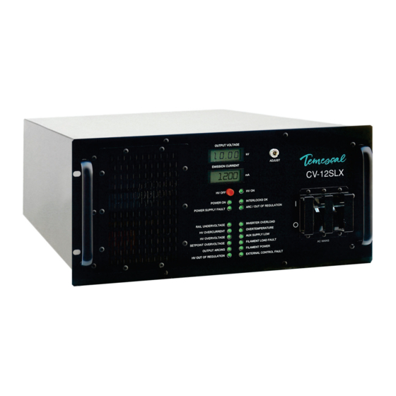
ferrotec Temescal CV-12SLX User Manual (94 pages)
Brand:
ferrotec
| Category:
Power Supply
| Size: 11.91 MB
Table of Contents
Table of Contents
3
Introduction to the CV-12SLX
13
Product Description
13
CV-12SLX HVPS Description and Specifications
13
Figure 1-1 CV-12SLX HVPS Front Panel
13
Filament Power Supply Description and Specifications
14
Figure 1-2 Filament Power Supply Front Panel
14
Miscellaneous Hardware and Interconnection Cables
15
Figure 1-3 EBC Main Control Unit and Hand-Held Controller
15
Installation
17
Section Overview
17
List of Components and Cables Supplied with the Unit
18
Rack Mounting the Power Module (HVPS)
18
Mounting the Filament Power Supply Module(S)
19
Grounding Requirements
20
Figure 2-1 Mounting Hole Pattern for FPS Module(S)
20
Figure 2-2 Facility Low Impedance Grounding Requirements
21
Figure 2-3 System Low Impedance Grounding Requirements
22
Figure 2-4 Rear Panel of Single Gun CV-12SLX HVPS
23
Figure 2-5 Rear Panel of Dual Gun CV-12SLX HVPS
23
Figure 2-6 Grounding Studs on FPS Front Panel
24
Cable Installation
25
Figure 2-7 Input Power Connections to 208-Volt HVPS Units
26
Figure 2-8 Input Power Connections to 400-Volt HVPS Units
26
Figure 2-9 Input Power and HV Connections on FPS Front Panel
27
Figure 2-10 Removing the FPS Conduit Panel
28
Figure 2-11 Conduit Properly Secured to FPS Conduit Panel
28
Figure 2-12 HV Output Cables Secured to Studs Inside FPS
29
Figure 2-13 HV Conduit Bracket Properly Installed on HV Feedthrough
29
Figure 2-14 HV Conduit Properly Secured to Bracket
30
Figure 2-15 Control/Data Cable Connections on FPS Front Panel
30
Figure 2-16 System I/Os Exchanged Via HVPS Rear Panel Connector J4 and the HVPS I/O Cable (PN 0620-6682-0)
32
Figure 2-17 System I/Os Exchanged Via FPS Front Panel Connector J101 and the FPS I/O Cable (PN 0620-6672-2)
34
Power Supply Operation
37
Section Overview
37
HVPS Front Panel Controls and Indicators
37
Figure 3-1 CV-12SLX HVPS Front Panel
37
Switches and Leds on the FPS Front Panel
38
Figure 3-2 Filament Power Supply Front Panel
38
Power-Up Procedure
39
Figure 3-3 Ebc's Operations>E-Beam Screen When Beam Is off
40
Figure 3-4 Operations>E-Beam Screen, Beam on at 0.0 Ma
40
Figure 3-5 Operations>E-Beam Screen When Gun Is on and HV Is off
41
Figure 3-6 Operations E-Beam Screen with Numeric Keypad Displayed
41
Figure 3-7 Operations>E-Beam Screen, Beam on at 5% Power
42
Figure 3-8 the Ebc's Diagnostics Screen
42
Control of Power Supply by a PLC-Based System Controller
44
Figure 3-9 Remote Controller's LOCAL Screen, Menu 1 Selected, Beam and Sweep off
44
Figure 3-10 HVPS Front Panel Leds: HVPS Powered up in Nominal State, with HV and FPS off
45
Responding to Fault Conditions
47
Figure 3-11 HVPS Front Panel Leds When Subthreshold Arcing Is Occurring
48
Figure 3-12 HVPS Front Panel Leds When a Latched OUTPUT ARCING Fault Has Occurred
48
Theory of Operation
49
Section Overview
49
HVPS Theory of Operation
49
Figure 4-1 Single-Gun CV-12SLX HVPS Rear Panel
49
Figure 4-2 Dual-Gun CV-12SLX HVPS Rear Panel
50
4.3 FPS Theory of Operation
52
Figure 4-3 Filament Power Supply (FPS) Module
52
Figure 4-4 Component Location in Standard FPS Units (PN 0620-6604-0 and -1)
53
Figure 4-5 Top Level Block Diagram for Standard FPS Units (PN 0620-6604-0 and -1)
54
Figure 4-6 Component Location in FPS Units with PN 0620-6604-2
55
Figure 4-7 Top Level Block Diagram for FPS Units with PN 0620-6604-2
55
Figure 4-8 Filament Supply PCB Overview Block Diagram
56
Figure 4-9 Block Diagram of Filament Supply PCB Control and Power Circuits
58
Figure 4-10 Emission Current Ramp Circuit
59
Figure 4-11 Autobias Circuit Block Diagram
60
Troubleshooting
61
Section Overview
61
HVPS Front Panel Leds
61
Figure 5-1 HVPS Front Panel Leds
62
Figure 5-2 Status Indicator Leds
62
Figure 5-3 Sub-Threshold Arcing: Arc/Out of Regulation and Output Arcing Leds
63
Figure 5-4 Filament Load Fault and Filament Power Leds
63
Figure 5-5 HVPS Front Panel Leds with Latching Fault Leds Outlined
64
Figure 5-6 Interlocks OK and Rail Undervoltage Leds
64
Figure 5-7 HV Overcurrent and HV Overvoltage Leds
64
Figure 5-8 Setpoint Overvoltage and Output Arcing Leds
65
Figure 5-9 Inverter Overload and Overtemperature Leds
65
Figure 5-10 Aux Supply Low and External Control Fault Leds
66
Ishikawa Diagrams
67
Ishikawa Diagram #2: Interlock Fault
67
Ishikawa Diagram #1: no Input Power
67
Ishikawa Diagram #3: no Beam after HV and Gun Are Switched on
68
Ishikawa Diagram #4: HV Output Unstable
68
Ishikawa Diagram #5: HV out of Regulation LED Lights Frequently
69
Ishikawa Diagram #6: Arc/Out of Regulation LED Lights Excessively for the Material/Application
69
Ishikawa Diagram #7: Rail Undervoltage Fault
70
Ishikawa Diagram #8: HV Overcurrent Fault
70
Ishikawa Diagram #9: HV Overvoltage Fault
71
Ishikawa Diagram #10: Setpoint Overvoltage Fault
71
Ishikawa Diagram #11: Output Arcing Fault
72
Ishikawa Diagram #12: Overtemperature Fault
72
Ishikawa Diagram #13: Aux Power Supply Low Fault
73
Ishikawa Diagram #14: External Control Fault
73
Ishikawa Diagram #15: Filament Load Fault
74
Ishikawa Diagram #16: Simultaneous Filament Load Fault + Filament Power Fault
74
Troubleshooting Procedures
75
Ishikawa Diagram #17: Emission Current Unstable
75
Table Number and Title
76
Table 5-1 no Input Power Indicated
76
Table 5-2 One or more Interlocks Not Made
77
Table 5-3 General Condition: HVPS Powered up but Fails to Achieve HV Ready State
77
Table 5-4 HVPS and FPS Are Powered up but GUN READY State Not Achieved/Confirmed
78
Table 5-6 FPS Powered up but Gun Does Not Switch on When Commanded to Do so
79
Table 5-7 no Filament Current after GUN on State Is Achieved
79
Table 5-8 no Beam Emitted after HV and Gun Are Switched on
80
Table 5-10 Filament Current out of Regulation
81
Table 5-11 HVPS ARC/OUT of REGULATION LED Flashes Excessively
81
Table 5-12 HVPS RAIL UNDERVOLTAGE LED Lights Red
82
Table 5-13 HVPS HV OVERCURRENT LED Lights Red
83
Table 5-14 HVPS HV OVERVOLTAGE LED Lights Red
84
Table 5-15 HVPS SETPOINT OVERVOLTAGE LED Lights Red
85
Table 5-16 HVPS OUTPUT ARCING LED Lights Red
85
Table 5-17 HVPS INVERTER OVERLOAD LED Lights Red
86
Table 5-18 HVPS OVERTEMPERATURE LED Lights Red
87
Table 5-19 Fan Fails to Rotate When HVPS Is Powered up
87
Table 5-20 HVPS AUXILIARY SUPPLY LOW LED Lights Red
88
Table 5-21 HVPS EXTERNAL CONTROL FAULT LED Lights Red
88
Table 5-22 HVPS FILAMENT LOAD FAULT LED Lights Red
88
Table 5-23 HV Is Switched on but FPS Front Panel HIGH VOLTAGE on LED Fails to Light
89
Table 5-24 FPS #1 Is Switched on but Its POWER on LED Fails to Light
89
Table 5-25 FPS #2 Is Switched on but Its POWER on LED Fails to Light
89
FPS Fuse Replacement Procedure
90
Figure 5-11 Prying Open the Fuse Block Cover on FPS Front Panel
90
5.6 Suggested Spare Parts
91
Figure 5-12 Extracting the Fuse Block from the FPS
91
Figure 5-13 Fuse Block Removed from FPS
91
Table 5-26 Suggested Spare Parts for 208-Volt Units
91
Table 5-27 Suggested Spare Parts for 400-Volt Units
92
Advertisement
Advertisement
Related Products
FerroTec CARRERA
ferrotec Temescal CV-6SLX
ferrotec Temescal FC-4400
ferrotec Categories
Power Supply
Industrial Equipment
Control Unit
Controller
More ferrotec Manuals
Login
Sign In
OR
Sign in with Facebook
Sign in with Google
Upload manual
Upload from disk
Upload from URL