Table of Contents
Advertisement
Advertisement
Table of Contents

Related Manuals for Lauda PROLINE P 5 C


Summary of Contents for Lauda PROLINE P 5 C
- Page 1 Operating instructions PROLINE heating thermostat Thermostats with PowerAdapt system Heating thermostats P 5 C Calibration thermostat PJ 12 C, PJL 12 C Clear view thermostats PV 15 C, PVL 15 C, PV 24 C, PVL 24 C, PV36 C Bridge thermostats PB C, PBD C Read the instructions before starting all work!
- Page 2 Manufacturer LAUDA DR. R. WOBSER GMBH & CO. KG Laudaplatz 1 97922 Lauda-Königshofen Germany Phone: +49 (0)9343 503-0 Fax: +49 (0)9343 503-222 E-Mail info@lauda.de Internet https://www.lauda.de Q4DA-E_13-009-DE-01 Translation of the original operating instructions English / Release 02/2022 A Valid from: Software of Operating system (Command) version 3.45...
-
Page 3: Prefixed Safety Notes
Prefixed safety notes Before operating the equipment please read carefully all the instructions and safety notes in Section 1. If you have any questions please phone us! Follow the instructions on setting up, operation etc. This is the only way to avoid incorrect operation of the equipment and to ensure full warranty protection. -
Page 4: Table Of Contents
Content Prefixed safety notes..................................3 SAFETY INFORMATION ................................7 .............................. 7 ENERAL SAFETY INFORMATION ..............................8 THER SAFETY INFORMATION BRIEF OPERATING INSTRUCTIONS ............................9 CONTROLS AND FUNCTIONAL ELEMENTS ........................11 DEVICE DESCRIPTION ................................15 ............................. 15 NVIRONMENTAL CONDITIONS ..................................15 EVICE TYPES .................................. - Page 5 7.7.6 Setting the date and time ............................. 45 7.7.7 Display resolution setting .............................. 45 ................................... 46 PECIAL SETTINGS 7.8.1 Setpoint resolution ................................ 46 7.8.2 Defining the type of start mode ........................... 46 7.8.3 Defining temperature limits............................48 7.8.4 Setpoint offset operating mode ........................... 49 7.8.5 Restoring works settings ...............................
- Page 6 8.3.3 Connecting cable RS 485 ............................92 8.3.4 Protocol RS 485 ................................93 8.3.5 Write commands (Data commands to the thermostat) .................... 93 8.3.6 Read commands (Data requested from the thermostat) ..................95 8.3.7 Error messages ................................97 8.3.8 Driver software for LABVIEW® ..........................97 ................................
-
Page 7: Safety Information
Safety information General safety information A laboratory thermostat heats and circulates liquids according to specified parameters. This involves hazards due to high temperatures, fire and general hazards due to the application of electrical energy. The user is largely protected by the application of relevant standards. Further hazard sources may arise due to the type of tempering medium, e.g. -
Page 8: Other Safety Information
Other safety information Only connect equipment to PE grounded mains sockets. At higher operating temperatures, parts of the bath cover can reach surface temperatures exceeding 70 °C. Be careful when touching it Risk of burning! Use suitable hoses ( 6.4). Secure hose against slippage with the aid of hose clips. -
Page 9: Brief Operating Instructions
Brief operating instructions These brief instructions shall give you the possibility to operate the unit quickly. For safe operation of the unit, it is absolutely necessary to read carefully all the instructions and safety notes! 1. Assemble unit and add items as appropriate ( 6.1). Take care of the hose tubing connections (... - Page 10 Menu structure: Command remote control intern Pt100 Pump Level Calibration Menu extern Pt100 Default Calibration all default All Modules Works settings Master Resolution All default Command Device status Only control par. int. Contact Display data Only control par. ext. Other connected Basic settings Only miscellaneous modules...
-
Page 11: Controls And Functional Elements
Controls and functional elements Command remote control (see page 16) Bath cover Master control panel (see page 16) Recessed grip Mains switch 4 Feet Pump connection at side and bypass-valve (see illustration below) Side pump connection: Pumpe outflow, pressure output (closed off with screw plug) Bypass valve (in “external”... - Page 12 Cover for the two module slots Mains supply head Rear pump connection: Connection socket for the external Pt100 temperature probe Suction nozzle (return to bath) Connection socket (CAN 1 and 2) for bus suitable for unit and to Pumpe outflow (pressure output) which the refrigerating lower section and Command remote control 10 Cooling coil: Cooling water inlet connection are connected.
- Page 13 Clear view thermostat PVL 24 Bridge thermostat PB C 02/2022 Proline heating thermostat 13 / 123...
- Page 14 Control element: “Master” Display : Cooler active (blue LED is lit) : The temperature of an external source is displayed : Bath controlled by external temperature (EXT is lit green). source (green LED lits) : Error signal (red LED blinking) : Enter key : Select keys : Overtemperature set point to check or set Tmax...
-
Page 15: Device Description
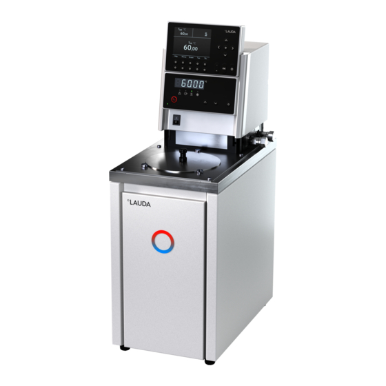
P 5 C is a Bath thermostat with 5-liter bath and Command remote control. PVL 15 is a clear view thermostat with 15-liter bath and operating temperature up to -60 °C (with LAUDA add-on cooler). PJ 12 C is a calibration thermostat with 12-liter bath and Command remote control. -
Page 16: Materials
At the right-hand side and at the back of the unit outflow and inflow nozzles are fitted for external loads. This means that up to two external loads can be directly connected without a distributor. Connections which are not required must be closed off with the supplied caps and union nuts. -
Page 17: Programmer And Ramp Function
The Master unit is equipped with the following sockets at the back of the control head: For the connection of an external Pt100 temperature sensor (10S). Two sockets (70S) for the connection of components via the LAUDA equipment bus (cooling section, Command remote control, external solenoid valve, etc.). -
Page 18: Interface Modules (Accessories)
4. Contact Module (Order No. LRZ 914) with connector to NAMUR NE28. Functionality as LRZ 915, but only one output and one input on each of two DIN sockets. Coupling socket 3-pole, LAUDA Order No. EQD 047 and coupling plug 3-pole, LAUDA Order No. EQS 048. -
Page 19: Unpacking
After unpacking, firstly check the device and accessories for any damage in transit. If, contrary to expectations, there is visible damage to the unit, the carrier must be immediately informed, so that an investigation can be made. Please also inform the LAUDA Service (Contact 9.4). Standard Accessories:... -
Page 20: Preparation
Preparation Assembly and sitting Site the unit on a flat surface The unit must not be put into operation if its tem- perature during storage or transport has dropped below the dew point. Wait for about one hour. ... -
Page 21: Expanding The Working Temperature Range With External Cooling
When operating Proline heating thermostats above 100 °C to 300 °C, we recommend the LAUDA high-temperature cooler HTC, order number LCZ 9663. Operation with high-temperature cooler 02/2022... - Page 22 For bath temperatures above 155 °C it is not allowed to cool with water together with the simple cooling coil (water vapor risk of explosion). Especially for the Proline there is a controlled high temperature cooler for fast and time saving cooling with bath temperatures up to 300 °C (accessory LCZ 9663).
-
Page 23: Filling And Draining
Filling and draining Filling Close the drain cock! Carefully remove all residues of the previous heat transfer liquid (blow dry and remove screw plugs!). Maximum filling level is up to 10 mm below the top edge of the bath. Overfilling leads to the dis- WX103 play of the warning (... -
Page 24: Heat Transfer Liquids And Hoses
Observe the safety data sheets for the various heat transfer liquids. If required, you can download the safety data sheets from our homepage. Open the LAUDA homepage, tap Services Download center. In the Download center, chose the [Safety data sheet] option in the [Document type] drop-down list. - Page 25 Temperature range °C Field of application (cm) MC 50 LZM 040 — MC 100 LZM 041 — With simple insulation, for all LAUDA heat transfer liquids MC 150 LZM 042 — MC 200 LZM 043 — MK 50 LZM 052 —...
-
Page 26: Connecting External Loads
Connecting external loads Operation as circulating thermostat Bursting of the external consumer due to overpressure Scalding, frostbite, cutting Use a pressure relief device on pressure-sensitive consumers (e.g. glass reactors). When used as circulation thermostat, care for shortest hose connections with largest inner diameter as possible. This gives the best flow. -
Page 27: Starting Up
Starting up Mains connection Compare the rating on the nameplate (back of control head) with the mains voltage. Connect unit only to sockets with a protective earth conductor (PE). No liability is accepted for incorrect mains connections! Ensure that pump connectors without external loads are closed off. ... - Page 28 LEUEL Display for (low level) appears when the bath has too little liq- Level alarm uid. °C LEUEL Red LED above the fault triangle flashes. Find cause of fault and, where necessary, top up missing heat transfer liquid (...
-
Page 29: Switching Off
Switching off / standby Switching off: Set mains switch to position 0. Standby operation: Use the key on the Command remote control. The pump and heater are switched off. The operating display remains active, so that the device status is visible and adjustments can be made. The timer continues to run. - Page 30 The following always applies: After termination of the relevant settings, they are accepted automatically after approx. 4 s or the setting is accepted immediately with the Enter key. Fault signal: Flashing red Alarm LED and acoustic signal. ...
- Page 31 Brightness Contrast Brightness Display The brightness and contrast can be set on the Sounds Master Contrast Command remote control: Sounds Command Language The works setting can be changed via Master-Mode Settings Basic settings Autostart Display Brightness or ...
- Page 32 2. Standard window with five important items of °C Level information: T , current bath temperature, °C T , setpoint, T , current temperature on external probe (if connected), °C Pump Level of heat transfer liquid in cm above the minimum level, ...
-
Page 33: Changing Window Information
7.4.2 Changing window information Command Display data You can adapt the information displayed by your °C Level Command remote control to your requirements. For example, if you have not connected any tem- perature probe, you can exchange it in the standard °C setting of the normal window for the maximum tem- perature T... -
Page 34: Locking The Keyboard
7.4.3 Locking the keyboard The keyboards of the Master and the Command remote control can be locked independently of one another. This is especially advantageous when the thermostat is positioned in another room and the Command remote control is used as a remote control device. - Page 35 Command Locking: Press and then and hold pressed simul- Locking keyboard! taneously for 3 s. The locking window appears. Hold both keys pressed until the progress bar is completely filled. Then the display skips back to the previously set Screen mode.
-
Page 36: Menu Structure: "Master
UEr Software version Cur Max. current consumpt. Section 9.2.2 Menu structure: "Master" Section 7.7.5 S Setpoint resolution Snr_H Serial number Hi Word. MNEmv 2 dots in the display, e.g. , indicate that a Section 7.8.1 Section 9.2.3 submenu follows. StArt Opern. w. mains fail. Snr_L Serial number Lo Word. -
Page 37: Menu Structure: Command Remote Control
Menu structure: Command remote control intern Pt100 Pump Level Calibration Menu extern Pt100 Default Calibration all default All Modules Works settings Master Resolution All default Command Device status Only control par. int. Contact Display data Only control par. ext. Other connected Basic settings Only miscellaneous modules... -
Page 38: Important Settings
Important settings 7.7.1 Temperature setpoint setting The setpoint is the temperature which the thermostat should reach and maintain constant. Master (main level) Press key until (Setpoint) appears. Press, display flashes. Enter the setpoint with the two keys ( Section 7.4.1 General key func- tions and pilot lamps). - Page 39 Confirm the value with or quit the window with without having made any changes. Two other ways of entering the setpoint: Fixed settings Recent setpoints With the soft key open the window 0,00°C 80,00°C shown on the left. 0,00°C -35,50°C ...
-
Page 40: Displaying The Actual External Temperature
7.7.2 Displaying the actual external temperature With all Proline Thermostats an external temperature probe can be connected, which for example..1..can be used as an independent temperature measurement channel. 2..can be used as the controlled variable for the bath temperature in applications with a noticeable tem- perature gradient (between the internal bath temperature and an external load). -
Page 41: Setting Pump Power Or Standby
Command Provided an external temperature probe is con- °C Level nected, its value is displayed in the lower left part of the standard and super windows (applies to the works setting for the window partitioning). °C External actual temperatures can also be read in via interface modules. -
Page 42: Activating External Control
Command Pump level Open the device parameter menu via the soft Level 8 Pump level Menu . Level 7 Level 6 Change from Pump Pump level using Level 5 With you enter the illustrated win- Level 4 dow. -
Page 43: Current Consumption From The Mains
Change temperature probe source: for the internal probe, only when an external probe is connected, only when an analog module is connected and configured, only when a serial module is connected and is continuously receiving ac- tual values from a PC. - Page 44 Master Call current consumption MNEnu PArA The present setting is displayed. °C 1&0 The current consumption is shown flashing: e.g. Set the required maximum current consumption (in A). wait 4 seconds or Display flashes 4 s new value is automatically accepted, or ...
-
Page 45: Setting The Date And Time
7.7.6 Setting the date and time Command Clock Time Date Open the device parameter menu via the soft Pump Set time Settings Set date Menu . Graph Timer 1 With the cursor keys continue to: Clock Timer 2 Clock Set time Programmer... -
Page 46: Special Settings
Select the desired resolution with Accept selection with or End , Display resolution 0,01 or quit the window with without making 0,001 changes. Pump Menu Special settings 7.8.1 Setpoint resolution This function enables the resolution of the setpoint T to be increased from the standard value of 0.1 °C to 0.01 °C (only Master). - Page 47 StArt Master StArt Call the start option MNEnu PArA The start mode can be changed here. °C StArt Auto MNAn The display flashes. Auto , when operation is be restored automatically again after an inter- ruption. MNAn , when the standby mode is to be activated after a mains interrup- ...
-
Page 48: Defining Temperature Limits
7.8.3 Defining temperature limits With this function it is possible to define a minimum and a maximum temperature in which the thermostat controls. By reaching the temperature limits, a warning appears. In this way setpoint input can be prevented which may damage the heat transfer liquid or the apparatus. -
Page 49: Setpoint Offset Operating Mode
Enter the desired limit temperature. Accept the change with Lower limit (Til) or quit the window with without making -50, changes. Min: -50,0 °C Max: 301,0 °C Help Menu Screen 7.8.4 Setpoint offset operating mode With this function it is possible to apply an offset value to the temperature provided by the external temperature probe or a module and then to use it as the setpoint. - Page 50 Command Offset source Setpoint offset Open the device parameter menu via the soft Offset source Setpoint offset extern Pt100 Menu . RS232 With the cursor keys continue to: Control Setpoint offset Offset source indicates that the setpoint offset is cur- ...
-
Page 51: Restoring Works Settings
7.8.5 Restoring works settings Master If you would like to restore all the works settings except the control parameters and the probe calibrations call the works settings MNEnu PArA is displayed. °C Press longer than 3 seconds. 3 seconds long donE ... - Page 52 Under Master you have the choice between: All default , then all Master settings are reset, only control para int for the internal con- trol parameters, only control para ext similar for external, only miscellaneous which resets set- ...
-
Page 53: Setting The Volume Of The Acoustic Signals
7.8.6 Setting the volume of the acoustic signals The LAUDA Proline Thermostats signal alarms as a dual-tone acoustic signal and warnings as a continuous tone. Audio Master Audio Call the volume setting ( 7.5). MNEnu PArA Audio takes you to the alarm volume, °C... -
Page 54: Entering The Offset Of The Internal Temperature Probe
7.8.7 Entering the offset of the internal temperature probe If, during checking with a calibrated reference thermometer probe, a deviation is found, then the offset (i.e. the additive part of the characteristic) of the internal measuring chain can be adjusted with the following function. The reference thermometer must be dipped into the bath according to the details on the calibration certificate. -
Page 55: Restoring The Works Setting Of The Internal Temperature-Probe Offset
The temperature measurement device shows the true temperature value (with glass ther- Temperature value of the ref. mometers consider the correction where appli- temp. measurement device: cable!). Change the display in the adjacent window to the true value with cursor or soft keys and ac- cept with or End , Min: -50,0°C... -
Page 56: Entering The Offset Of The External Temperature Probe
Confirm the control dialog on the right with or cancel with Confirm input! Return to the measurement window with Enter key: Continue End or Escape key: Cancel Pump Menu 7.8.9 Entering the offset of the external temperature probe If a deviation is found during the check using a calibrated reference thermometer probe, then the offset (the additive part of the characteristic) of the external measurement chain can be adjusted with the following function. -
Page 57: Restoring The Works Setting Of The External Temperature-Probe Offset
7.8.10 Restoring the works setting of the external temperature-probe offset If the offset has been misadjusted unintentionally, the works setting can be restored with this function. dEF E Master Call the offset works setting for the external temperature probe MNEnu CAL.. -
Page 58: Graphical Display Of Temperature Measurements
Graphical display of temperature measurements Command Screen and Graph 25,00 25,01 25,02 Press the soft key Screen a number of T °C 27,00 times as required until the graph recorder win- dow appears. 26,00 25,00 With the soft key Graph you enter the menu for the configuration of the graph record- 24,00... - Page 59 Temp. scale defines how the scaling is to be carried Mode Temp. min 22,00 out: Displayed value Temp. max 27,00 Automatic , by the program, or Legend Sample time Manual in that you yourself define the limits Time axis with the next menu point.
-
Page 60: Programmer
7.10 Programmer (PGM) Almost any temperature/time profile can be created with the programmer. A desired bath temperature can be approached as quickly as possible or via a defined ramp. Furthermore, the pump level and the behavior of the switching outputs can be defined. - Page 61 Each program begins with the segment "Start". It defines at which temperature Segment 1 is to contin- ue the program. It is not possible to specify a time for the Start segment. Without the Start segment, Segment 1 would be different depending on the bath temperature at the start of the program. For heating thermostats the start temperature must be set above the actual bath temperature during program start together with a sufficient tolerance to allow reaching the set temperature without cooling (especially if no additional cooling is available).
-
Page 62: Selecting And Starting The Program (Start, Hold, Stop)
°C Example for the influence of the Tolerance field input in case of external bath temperature control: The setpoint temperature of the programmer is shown in grey. The actual temperature in the external bath contain- er is represented as a continuous line. ... -
Page 63: Interrupting, Continuing Or Terminating The Program (Hold, Continue, Stop)
Commands, which depending on the situation cannot be executed, are not displayed. Continue therefore only appears, when Hold has been activated. Once the start has been confirmed with Hold Status Prog. 1 running appears at the bottom. Stop Edit Loops Graph Info... -
Page 64: Creating Or Modifying A Program (Edit)
Continue Status In addition, the standby key stops the pro- Stop Edit grammer! Pump and heater are switched off. Loops Follow the safety information ( 7.7.3). Graph Info After pressing the standby key again, the programmer returns to the previously selected operating mode: Pause or active operation depending on what was previously selected. - Page 65 Command Programmer Program1 Edit Modify In the Edit menu one can Modify Delete Status Modify a program. Delete Edit Press the key. Loops Graph Continue to Modify . with the key Info There is the possibility of modifying single seg- ments, i.e.
- Page 66 If the tolerance range has been selected too small, it may be that the program does not continue, be- cause the required tolerance is never achieved. External temperature control: Especially with ramps, a too close tolerance range can cause undesired delays in the start phase of the ramp.
- Page 67 If the field in the column Time has a black background, the entry mode for the "Segment time" time setting is obtained by pressing the key. Input segment time: If 0 is entered into the field "Time", ------ ap- pears.
- Page 68 The contact outputs of the contact module (if ------- Contact out present, special accessory) are programmed Open here. Closed If the field in the column "Out 1" has a black background, the entry mode for the Contact output is obtained by pressing the key.
-
Page 69: Defining The Number Of Program Loops (Loops)
7.10.5 Defining the number of program loops (Loops) Command Programmer Program1 Loops If required, programs can be looped many Status times. Edit With access the menu Loops Loops Graph Select the number of desired program loops. Info Pump Menu ... -
Page 70: Obtaining Information On A Program (Info)
The display of the programmed temperature T °C 27,00 curve can be quit with or End . 26,00 25,00 24,00 23,00 Pump 00:00 Menu 00:45 01:30 02:15 7.10.7 Obtaining information on a program (Info) Command Programmer Program1 Info Continue with to Info. -
Page 71: Ramp Function
7.11 Ramp function With the ramp function temperature changes over any time period can be conveniently entered. This is especially ad- vantageous with very low temperature changes (e.g. 0.1 °C per day). Example: From the current outflow temperature (e.g. 242.4 °C), 200 °C of cooling is to occur over 5 days. Then the temperature change is entered as 200 °C and the time as 5 days. -
Page 72: Timer Function
7.12 Timer function Using the timer function, the thermostat can carry out an action at a certain time or after a certain waiting period. The actions are: Switching on the thermostat, entering the standby mode or one of the five programs in the programmer. Command Timer 1 Timer 2 ... - Page 73 Week plan Week plan Arrange takes you to the win- Time Action Time Action dow shown on the left. Monday 07:30 Start 17:00 ------- Using the cursor keys select the field, Tuesday 10:00 Prog.4 17:00 ------- which is to be filled in. Wednesday 08:00 ------- 17:00 ------- ...
-
Page 74: Control Parameters
7.13 Control parameters The control parameters are optimized ex-works for operation as a bath thermostat (with water as the heat transfer liq- uid) with internal control. The parameters are also preset for the operation of external containers with external control. Sometimes however, the operation of external containers requires adaptation. -
Page 75: Proven Settings For Control Parameters And Pump (Internal Control)
Command Control Parameters Open the device parameter menu via the soft Control Parameters Control para. sets Menu . (auto) Tv manual/auto With the cursor keys continue to: (auto) Control Control Parameters Control Parameters The adjacent window appears. ... -
Page 76: External Control Variable (External Measurement Probe)
7.13.2 External control variable (External measurement probe) You only need to read further here if you have connected an external temperature probe or the actual temperature is read in from a module (and you have activated it as control variable according to ( Section 7.7.4)). Only modify the control parameters if you have knowledge of control techniques. -
Page 77: Proven Settings For Control Parameters And Pump (External Control)
Command Control Parameters Open the device parameter menu via the soft Control Parameters 0,50 Control parameter sets Menu . Tve (auto) 83 Tv manual/auto With the cursor keys continue to: Tde (auto) Correction limitation Control Control Parameters Con- ... - Page 78 Ethanol Minimum 40 °C Tools to watch the time behavior: Graph mode of the Command remote control, LAUDA Wintherm PC-program. 78 / 123 Proline heating thermostat 02/2022...
-
Page 79: Internal And External Control Parameter Sets
7.13.3 Internal and external control parameter sets If a thermostat is used for a number of applications, which always leads to a change of the control parameters, these control parameters (up to 9 sets) can be saved in the thermostat and activated again as required. Also saving is useful for finding the best control parameters;... -
Page 80: Alarms, Warnings And Errors
Errors: When an error occurs, switch of the device. If the error is always present after switching on the de- vice, please inform the LAUDA Service ( 9.4). Find cause of alarm or warning and rectify where necessary. Then press on the Master keyboard in order to remove the alarm message. - Page 81 Quit the change mode by pressing again or automatically after 5 seconds, while you keep pressed. This somewhat complicated procedure is intended to prevent unintentional adjustment. Set the overtemperature switch-off point Tmax below the flash point of the heat transfer liquid (...
-
Page 82: Low-Level Alarm And Low-Level Checking
If irregularities arise during the checking of the safety devices, switch off the unit immediately and pull out the mains plug! Have the equipment checked by LAUDA Service. Command Low-level alarm! Low-level alarm is shown in the display and signifies that unlocking is only possible on the ... -
Page 83: High-Level Settings
7.14.3 High-level settings Different reactions can be chosen when the level sensor detects the height of the heat transfer liquid level. Depending on the setup, heat transfer liquid or operation conditions, one of the following settings may be suitable: Setting Master set- Command set- Reaction and application recommendation... -
Page 84: High-Level Warning Or Alarm
7.14.4 High-level warning or alarm Acoustic warning signal sounds for 3 seconds when the liquid level rises so far 3 Sec. that the uppermost switching point of the level sensor has been reached. Or in case the warning function as described in ( 7.14.3) was chosen: ... -
Page 85: Pump-Motor Supervision: Overload Or Blockage
7.14.5 Pump-motor supervision: Overload or blockage The SelfCheck Assistant monitors the Varioflex Pump: 1. Alarm sounds as dual-tone signal for pump-motor overload or blockage. bL0C 2. Display of signals blockage. Pump alarm °C 3. Red LED above the fault triangle flashes. -
Page 86: Fault List "Alarms And Warnings
7.14.7 Fault list “Alarms and Warnings” Alarms Message Meaning Pump too fast (low level) PuLEU Low level alarm in the level sensor LEUEL Overtemperature (t > tmax) tEMNP Pump blocked (no rotation) bL0C Command connection interrupt CFA1L Temperature signal of external Pt100 missing Temperature signal of analogue input missing Temperature signal of serial port missing Analogue module: Current input 1 interrupted... - Page 87 Warnings from “Command-Display” Warnings from “Cooling system” Message Meaning Message Meaning Overflow of CAN receipt Overflow of CAN receipt WX201 WX301 Watchdog-Reset Watchdog-Reset WX202 WX302 RTC Voltage drop recognised: Battery failure sm.stell_min still not determined Adaption run WX203 WX303 necessary Software version of control system too old Pressure switch 1 operated...
- Page 88 Software version of Pump 0 too old Software version of Pump 0 too old WX421 WX521 Software version of Pump 1 too old Software version of Pump 1 too old WX422 WX522 Software version of Pump 2 too old Software version of Pump 2 too old WX423 WX523 Software version of Pump 3 too old...
-
Page 89: Interface Modules
Interface modules Installing modules The master and command can be supplemented with further interface modules which are simply inserted at the back of the control head into two module slots. Touch the earthed bath cover of the Proline thermostat to discharge any electrostatic charge. -
Page 90: Menu Structure For All Modules
Menu structure for all modules All existing menu points are illustrated. However, the Command remote control masks out menu points, which cannot be executed. Further information can be found in the following sections. RS232 RS485 2400 Setpoint temperature Menu Ext. actual temp. 4800 9600 Pump power... -
Page 91: Rs 232/485 Serial Interface
RS 232/485 interface module (catalogue no. LRZ 913) with 9-pole SUB-D socket. Electrically isolated by opto- coupler. With the LAUDA instruction set essentially compatible to the ECO, Ecoline, Integral XT and Integral T Se- ries. The RS 232 interface can be connected directly to the PC with a 1:1 through-contact cable (catalogue no. EKS 037). -
Page 92: Protocol Rs 232
8.3.2 Protocol RS 232 The interface operates with 1 stop bit, no parity bit and 8 data bits. Transfer rate either: 2400, 4800, 9600 (factory setting) or 19200 baud as selected. The RS 232 interface can be operated with or without hardware handshake, (RTS/CTS). ... -
Page 93: Protocol Rs 485
An RS 485 bus always requires bus termination in the form of a termination network which ensures a defined rest status in the high-resistance phases of bus opera- tion. The bus termination is as follows: This termination network is usually incorporated on the PC plug-in card (RS 485). 8.3.4 Protocol RS 485 ... - Page 94 OUT_PAR_07_XX.X Setting of control parameter TdE OUT_PAR_09_XXX.X Setting of the correction limitation OUT_PAR_10_XX.X Setting of control parameter XpF OUT_PAR_14_XXX.X Setting of the setpoint offset OUT_PAR_15_XXX Setting of control parameter PropE OUT_MODE_00_X Keyboard Master: 0 = free / 1 = locked (corresponds to “KEY”) OUT_MODE_01_X Control: 0 = internal / 1 = external Pt100 / 2 = external Analogue / 3 = external Serial...
-
Page 95: Read Commands (Data Requested From The Thermostat)
8.3.6 Read commands (Data requested from the thermostat) Command Explanation IN_PV_00 Read bath temperature (outflow temperature) IN_PV_01 Indication of the controlled temperature (internal/external Pt/external Ana- logue/external Serial) IN_PV_03 Read external temperature TE (Pt100) IN_PV_04 Read external temperature TE (Analogue input) IN_PV_05 Read current bath level IN_PV_10... - Page 96 Command Explanation IN_MODE_00 Keyboard Master: 0 = free / 1 = locked IN_MODE_01 Control: 0 = int. / 1 = ext. Pt100 / 2 = ext. Analogue / 3 = ext. Serial IN_MODE_02 Standby operation: 0 = Device ON / 1 = Device OFF IN_MODE_03 Keyboard Command Remote Control: 0 = free / 1 = locked IN_MODE_04...
-
Page 97: Error Messages
® with the aid of the National Instruments program development tool LABVIEW (http://sine.ni.com/apps/we/nioc.vp?cid=1381&lang=US). In order to make program operation possible on the RS 232/485 interface, LAUDA provides drivers specially de- ® signed for LABVIEW which can be downloaded free of charge underFehler! Hyperlink-Referenz ungültig.. -
Page 98: Analogue Module
Analogue module The analogue module (order no. LRZ 912) has 2 inputs and 2 outputs which are brought out on a 6-pole DIN socket to Namur Recommendation (NE28). The inputs and outputs can be set independently as 4 – 20 mA, 0 –... -
Page 99: Contact Module
Contact module 8.5.1 Contact module LRZ 915 with three inputs and three outputs Contact module Cat. No. LRZ 915) on 15 pole SUB-D socket. With three relay contact outputs (changeover, max. 30 V/0.2 A) and three binary inputs for control via external voltage-free contacts. The following functions are made available by the inputs: Set fault with function: Master: F ALA or Command: Fault... -
Page 100: Namur-Contact Module Lrz 914 With Only One Input And One Output
8.5.2 Namur-Contact module LRZ 914 with only one input and one output Contact module (Cat. no. LRZ 914) with connector to NAMUR NE28. Functionality as LRZ 915, but only one out- put and one input on each of two sockets. Contact module LRZ 914;... -
Page 101: Maintenance
Maintenance Cleaning Withdraw the equipment mains plug before cleaning! Cleaning can be carried out with water to which a few drops of surfactant (washing-up liquid) have been added and using a damp cloth. No water must enter the control section! ... -
Page 102: Device Data
9.2.4 Device data Master MNEmv ShoWX ( Section 7.5) Various device datas are displayed. Command Device data Settings Device status Device T ext Pt 25.70 Tint 25,58 data Display T ext analog ---.-- Mains U(%) 103.74 T ext serial ---.-- Mains Frequ. -
Page 103: Servicing, Repair And Disposal Information
Keep to service intervals ( 9.3.2). If servicing does not occur at the stated intervals, then the manufacturer can no longer guarantee the safe operation of the thermostatic circulator. 9.3.1 Servicing LAUDA Thermostats largely require no service. If the heat transfer liquid becomes contaminated, it should be re- placed ( 6.3). ... -
Page 104: Servicing Intervals
9.3.4 Repair information If you need to send in a unit for repair, it is essential to first contact the LAUDA Service ( 9.4). If the equipment does have to be returned to the factory, it may only be necessary to dismantle the control head from the bath vessel and return the control head. -
Page 105: Disposal Of The Packaging
Service, ordering replacement parts and rating label When ordering spares please state the serial number (rating label). This avoids queries and supply of incorrect items. Rating label Contact the LAUDA Service in the following cases: In the event of faults on the device For technical questions about the device ... -
Page 106: Accessories
PC Program as a graph with free choice of time frame. Incl. RS 232 cable (2 m). RS 232/485 Interface modules Digital Communication, operation of the LAUDA PC LRZ 913 software Wintherm Plus ( 8.3) Analogue module Current and voltage interface ( 8.3.1) - Page 107 Round cover for PJ 12, PJ 12 C, PJL 12, PJL 12 C. HDR 028 LiBus = LAUDA internal BUS (based on CAN) ID = Immersion depth for test tubes We will inform you about other accessories on request ( 9.4). Also, refer to our special and accessory broachers.
-
Page 108: Technical Data And Diagrams
Technical data and diagrams The figures have been determined according to DIN 12876 Heating thermostat P 5 C Working temp. range (WT) °C 35 – 300 WT with water cooling °C 20 – 300 Operating temperature range °C -30 –... - Page 109 Table 2 Clear view thermostats PV 15 C PV 24 C PV 36 C PVL 15 C PVL 24 C Working temp. range (WT) °C 30 – 230 30 – 230 30 – 230 30 – 100 30 – 100 ...
- Page 110 Table 3 Bridge thermostats Calibration thermostats PB C PBD C PJ 12 C PJL 12 C Working temp. range (WT) °C 30 – 300 30 – 300 30 – 300 30 – 200 WT with water cooling °C 20 – 300 20 –...
- Page 111 Data applicable to all Proline heating thermostats Ambient temperature range °C 5 – 40 Relative humidity maximum relative humidity 80 % for temperatures up to 31 °C, decreasing line- arly to 50 % relative humidity at 40 °C Storage temperature range °C -20 –...
- Page 112 Heating curve for P 5 C, PJ 12, PJL 12 (PJL 12 up to 200 °C) measured with Ultra 300, bath covered Heating curve for PV 15, PV 24, PV 36, PVL 15, PVL 24 (PVL 15 and PVL 24 up to 100 °C) measured with Ultra 230, bath covered 112 / 123 Proline heating thermostat...
- Page 113 Pump characteristics measured with water 02/2022 Proline heating thermostat 113 / 123...
- Page 114 Pump characteristics measured with water 114 / 123 Proline heating thermostat 02/2022...
-
Page 115: Declaration Of Conformity
Declaration of Conformity 02/2022 Proline heating thermostat 115 / 123... -
Page 116: Index
Index Acoustic signals ........53 Decimal-point key ......... 30 Graph ............69 Activate standby ........41 dEF works settings ........ 51 Graph Graph recorder ......58 Activating external control ....42 dEF 1 Offset, works setting ....55 Graphical display ........58 dEF E Offset, works setting .... - Page 117 Standby operation ......... 29 Loops ............69 Pump level ..........42 StArt Type of start mode ....47 Low-level alarm ........82 Pump-motor supervision Starting up ..........27 Dry running ........85 Status ............62 Overload..........85 Super window ......... 32 Main fuse switch ........
- Page 120 Manufacturer LAUDA DR. R. WOBSER GMBH & CO. KG ◦ Laudaplatz 1 ◦ 97922 Lauda-Königshofen Telephone: +49 (0)9343 503-0 ◦ Fax: +49 (0)9343 503-222 E-mail: info@lauda.de ◦ Internet: https://www.lauda.de...
Need help?
Do you have a question about the PROLINE P 5 C and is the answer not in the manual?
Questions and answers