Sign In
Upload
Download
Table of Contents
Contents
Add to my manuals
Delete from my manuals
Share
URL of this page:
HTML Link:
Bookmark this page
Add
Manual will be automatically added to "My Manuals"
Print this page
×
Bookmark added
×
Added to my manuals
Manuals
Brands
Lauda Manuals
Thermostat
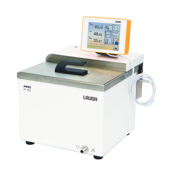
P 10
Operation manual
Lauda P 10 Operation Manual
Pro bath thermostats and circulation thermostats with base remote control
Hide thumbs
Also See for P 10
:
Operation manual
(160 pages)
1
2
Table Of Contents
3
4
5
6
7
8
9
10
11
12
13
14
15
16
17
18
19
20
21
22
23
24
25
26
27
28
29
30
31
32
33
34
35
36
37
38
39
40
41
42
43
44
45
46
47
48
49
50
51
52
53
54
55
56
57
58
59
60
61
62
63
64
65
66
67
68
69
70
71
72
73
74
75
76
77
78
79
80
81
82
83
84
85
86
87
88
89
90
91
92
93
94
95
96
97
98
99
100
101
102
103
104
105
106
107
108
109
110
111
112
113
114
115
116
117
118
119
120
121
122
123
124
125
126
127
128
129
130
131
132
133
134
135
136
page
of
136
Go
/
136
Contents
Table of Contents
Bookmarks
Table of Contents
Table of Contents
1 Safety
Safety Structure of the Devices
EMC Requirements
Software Versions
Observing Additional Operating Instructions
Intended Use
Foreseeable Misuse
Prohibition of Modifications to the Device
Materials
Fluorinated Refrigerant
Natural Refrigerant
Heat Transfer Liquid Requirements
Hose Requirements
Application Area
Personnel Qualification
Personal Protective Equipment
Personal Protective Equipment
Safety Fittings on the Device
Overtemperature Protection
Low-Level Protection
Warning Symbols on the Device
Structure of Warnings
2 Unpacking
3 Structure and Function
Structure
Structure of the Bath Thermostat
Structure of the Circulation Thermostats
Operating Elements
Mains and Safety Switch
Release Button and Maximum Temperature Knob
Functional Elements
Hydraulic Circuit
Refrigerating Machine
Heat Discharge through Cooling in a Hybrid Design
Nitrogen Overlay
Series Standard and Optional Interfaces
Type Plate
4 Before Starting up
Installation
Installing Interface Modules
RS 232 Interface
Cable and Test of the RS 232 Interface
Protocol RS 232
Connecting Cable RS 485
Protocol RS 485
Ethernet Interface
Connections Via the Ethernet Interface
Configuring the Ethernet Interface
Data Transfer Rate
Protocol of the Interface
Read and Write Errors on the Interfaces
Write Commands of the Interface
Read Commands of the Interface
Error Messages from the Thermostatic Circulator to the Control Station
Setting up the Circulation Thermostat
Racks, Platforms, Rising Platforms
External Consuming Unit
Hoses
Connecting an External Consuming Unit
Cooling Water
Cooling Water Requirements
Connecting the Cooling Water
5 Commissioning
LAUDA Heat Transfer Liquids
Filling the Device
Changing/Draining Heat Transfer Liquid
Establishing a Mains Connection
Switching on the Device
Display Buttons
Base Remote Control Unit Menu Structure
Setting Overtemperature Protection Tmax
Setting Temperature Limits Tih and Til
Setting the Temperature Target Value T
Basic Settings
Safety Mode
Adjusting the Volume of Signal Tones
Adjusting the Display Brightness
Operating Mode Following a Power Failure (Auto Start)
Limiting the Current Consumption
Selecting the Menu Language
6 Operation
General Safety Instructions
Operating Modes
Setting the Pump Level
Activating and Deactivating Standby and Operation Modes
Defining the Actuating Signal Limit
External Control
Activating External Control, Deactivating Internal Control
Setting the Set Point Offset
Programmer
Basic Information
Starting, Interrupting, Continuing and Ending a Program
Control Parameters
Control Basics
Overview of Internal Control Parameters
Overview of External Control Parameters
Opening the Control Menu
Editing Internal Control Parameters
Editing External Control Parameters
Calibrating the Temperature Probe
Viewing the Device Status
7 Maintenance
General Safety Instructions
Maintenance Intervals
Cleaning the Device
Cleaning the Air-Cooled Condenser
Cleaning the Water-Cooled Condenser
Checking the Heat Transfer Liquid
Checking the Overtemperature Protection
Checking the Low-Level Protection
8 Faults
Alarms, Warnings and Errors
Alarms
Control System Warnings
Safety System Warnings
Smartcool Warnings
9 Decommissioning
General Information on Decommissioning
Changing/Draining Heat Transfer Liquid
10 Disposal
Disposing of Refrigerant
Device Disposal
Disposing of Packaging
11 Technical Data
General Data
Refrigerating Machine and Cooling Water
Refrigerant and Filling Weight
Maximum Current Consumption and Heating Output
12 Accessories
13 General
Copyright
Technical Changes
Warranty Conditions
Contact LAUDA
EU Conformity
14 Glossary
15 Index
Advertisement
Quick Links
1
Alarms, Warnings and Errors
Download this manual
Operation manual
PRO bath thermostats and circulation thermostats
P 10, P 20, P 30, RP 3035, RP 2040, RP 2045, RP 1090, RP 2090, RP 10100, RP 240 E, RP 245 E, RP 250 E,
RP 290 E, P 2 E
with Base remote control
Read this manual prior to performing any task!
V04REV1 5
Table of
Contents
Previous
Page
Next
Page
1
2
3
4
5
Advertisement
Table of Contents
Need help?
Do you have a question about the P 10 and is the answer not in the manual?
Ask a question
Questions and answers
Related Manuals for Lauda P 10
Thermostat Lauda P 10 Operation Manual
(160 pages)
Thermostat Lauda PTT Operating Instructions Manual
(23 pages)
Thermostat Lauda PROLINE Kryomats Series Operating Instructions Manual
Low-temperature thermostats with smartcool system (115 pages)
Thermostat Lauda PROLINE P 5 C Operating Instructions Manual
(120 pages)
Thermostat Lauda PROLINE Edition X P 5 C Operating Instructions Manual
(116 pages)
Thermostat Lauda E 4 G Operating Instructions Manual
Heating and cooling thermostats with control head gold (119 pages)
Thermostat Lauda Ecoline RE 204 Operating Instructions Manual
Ecoline series low-temperature thermostats (69 pages)
Thermostat Lauda RM 6 T Operating Instructions Manual
Compact low temperature thermostats (31 pages)
Thermostat Lauda RCS 5 Operating Instructions Manual
Compact (39 pages)
Thermostat Lauda RP 845 Operating Instructions Manual
Low-temperature thermostats with smartcool system (127 pages)
Thermostat Lauda Integral XT 150 Operating Instructions Manual
Integral xt series. process thermostats / high-temperature thermostats (168 pages)
Thermostat Lauda L 100 Operating Instructions Manual
Thermo-electric circulation thermostat (48 pages)
Thermostat Lauda ECO Silver E 4 S Operation Manual
(128 pages)
Thermostat Lauda ECO GOLD Operation Manual
(136 pages)
Thermostat Lauda Ecoline RE 204 Operating Instructions Manual
Low-temperature thermostats (59 pages)
Thermostat Lauda Alpha Operating Instructions Manual
Heating and cooling thermostats (56 pages)
This manual is also suitable for:
P 20
P 30
Rp 3035
Rp 2040
Rp 2045
Rp 1090
...
Show all
Rp 2090
Rp 10100
Rp 240 e
Rp 245 e
Rp 250 e
Rp 290 e
P 2 e
Table of Contents
Print
Rename the bookmark
Delete bookmark?
Delete from my manuals?
Login
Sign In
OR
Sign in with Facebook
Sign in with Google
Upload manual
Upload from disk
Upload from URL


Need help?
Do you have a question about the P 10 and is the answer not in the manual?
Questions and answers