Table of Contents
Advertisement
Operating instructions
Integral XT
Process thermostats
XT 150, XT 250 W, XT 280, XT 280 W, XT 350 W, XT 350 HW, XT 490 W,
XT 550, XT 550 W, XT 750, XT 750 S, XT 750 H, XT 750 HS,
XT 950 W, XT 950 WS, XT 1590 W, XT 1590 WS,
XT 1850 W, XT 1850 WS
High-temperature thermostats
XT 4 H, XT 4 HW, XT 8 H, XT 8 HW
Advertisement
Table of Contents

Related Manuals for Lauda Integral XT 150


Summary of Contents for Lauda Integral XT 150
- Page 1 Operating instructions Integral XT Process thermostats XT 150, XT 250 W, XT 280, XT 280 W, XT 350 W, XT 350 HW, XT 490 W, XT 550, XT 550 W, XT 750, XT 750 S, XT 750 H, XT 750 HS, XT 950 W, XT 950 WS, XT 1590 W, XT 1590 WS, XT 1850 W, XT 1850 WS High-temperature thermostats...
- Page 3 High-temperature thermostats XT 4 H, XT 4 HW, XT 8 H, XT 8 HW Read the instructions before starting work! LAUDA DR. R. WOBSER GMBH & CO. KG YAWE0028 Translation of the original operating instructions Pfarrstraße 41/43 release 11/2016 h 97922 Lauda-Königshofen...
-
Page 5: Prefixed Safety Notes
Integral XT Prefixed safety notes Before operating the equipment please read carefully all the instructions and safety notes in Section 1. If you have any questions please phone us! Follow the instructions on setting up, operation etc. This is the only way to avoid incor- rect operation of the equipment and to ensure full warranty protection. -
Page 6: Table Of Contents
Integral XT Contents Prefixed safety notes ............................ 3 SAFETY INFORMATION ........................7 ......................7 ENERAL SAFETY INFORMATION ....................... 8 THER SAFETY INFORMATION BRIEF OPERATING INSTRUCTIONS ................... 10 ......................11 ENU STRUCTURE ASTER ......................12 ENU STRUCTURE OMMAND ..................... 13 IEW OF THE DEVICE AND CONNECTIONS CONTROLS AND FUNCTIONAL ELEMENTS ................ - Page 7 Integral XT 7.6.3.2 Permanently and automatic degassing ................... 54 7.6.4 Topping up ............................54 ............................55 RAINING ............56 HANGING THE HEAT TRANSFER LIQUID AND INTERNAL CLEANING ........................57 MPORTANT SETTINGS 7.9.1 Temperature setpoint setting ......................57 7.9.2 Displaying the actual external temperature ..................59 7.9.3 Pump capacity or setting standby ....................
- Page 8 Integral XT 7.16.6 Pump-motor supervision: Dry running ................... 109 7.17 RS232/RS485 I ) ........110 NTERFACE ONLY OMMAND REMOTE CONTROL OR ODULE 7.17.1 Connecting cables and interface test RS232 ................. 110 7.17.2 Protocol RS232 ..........................110 7.17.3 Connecting cable RS485 ....................... 111 7.17.4 Protocol RS485 ..........................
-
Page 9: Safety Information
Integral XT Explanation of signs: Danger: This sign is used where there may be injury to person- nel if a recommendation is not followed accurately or is disregarded. Note: Here special attention is drawn to some aspect. May include reference to danger. ... -
Page 10: Other Safety Information
Integral XT Device Immunity Emissions class Customer power supply Integral XT process Only for EU Type 2 in accordance Emissions Class B thermostat with in accordance with Domestic connection value single-phase and triple- DIN EN 61326-1 CISPR 11 ≥ 100 A phase devices Integral XT process Rest of the world (outside... - Page 11 When selecting the heat transfer liquid, observe the permissible temperature range. Heat transfer liquids from LAUDA are recommended which have been tested for use with the device ( 6.2). Always set the over temperature cut-off point immediately according to the heat transfer liquid used when filling (...
-
Page 12: Brief Operating Instructions
Integral XT Brief operating instructions These brief instructions shall give you the possibility to operate the unit quickly. For safe operation of the unit, it is absolutely necessary to read carefully all the instruc- tions and safety notes! 1. Set up the device or complete the configuration as required (þ 6.1). The device should never be tilted or stood upside down! Note the connection of the hose joints (þ... -
Page 13: Menu Structure: Master
Integral XT If instead, a warning or error message is displayed, then refer to Section 7.16. 9. Fill device with heat transfer liquid and follow Section 7.6. Use suitable heat transfer liquid (þ 6.2). The devices are rated for operation with non-flammable and flammable liquids according to DIN EN 61010-2-010. -
Page 14: Menu Structure: Command
Integral XT intern Pt100 Calibration Menu structure: Command extern Pt100 Default Pump Level All Modules All default Pressure control Master Only control par. int. Start Fill mode Command Only control par. ext. Menu Start Unfill mode Cool Only miscellaneous Max. Press.[bar] 1,0 Pump all default Start unfill heat exch. -
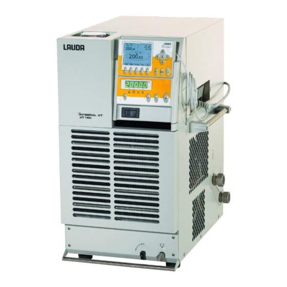
Page 15: View Of The Device And Connections
Integral XT View of the device and connections Integral XT 150 Main switch Filling point for heat transfer liquid Interface section Mains cable Drain point M16 x 1 Drain tap Refer to page 19 for an illustrated side view of connections and taps. - Page 16 Integral XT Integral XT 250 W Refer to page 19 for an illustrated side view of connections and taps. Brief operating instructions YAWE0028 / 24/06/2016...
- Page 17 Integral XT Integral XT 350 HW and XT 950 W(S) Refer to page 20 for an illustrated side view of connections and taps. Brief operating instructions YAWE0028 / 24/06/2016...
- Page 18 Integral XT Integral XT 280, XT 750 (S) und XT 750 H(S) Refer to page 20 for an illustrated side view of connections and taps. Brief operating instructions YAWE0028 / 24/06/2016...
- Page 19 Integral XT Integral XT 490 W, XT 1590 W, XT 1590 WS, XT 1850 W, XT 1850 WS Refer to page 20 for an illustrated side view of connections and taps. Brief operating instructions YAWE0028 / 24/06/2016...
- Page 20 Integral XT Rear view XT 150/ XT 250 W from XT 280 Overflow and venting for the equalizing container (all units) Switch for setting mains voltage and frequency (þ 2 and 9.4) (only XT 1850 W Order No. LWP 732; XT 1590 W Order No.
- Page 21 Integral XT Side view of connections (with XT 250 W as example) 1 Exit cooling water connection R3/4” (only water cooled devices W). 2 Entrance cooling water connection R3/4” (only water cooled devices W). 3 Pump connector outflow M30 x 1.5 (to the consumer). 4 Pump connector return M30 x 1.5 (from the consumer).
- Page 22 Integral XT Side view of connections and taps (with XT 350 HW as example) 1 Pump connector outflow M30 x 1.5 (to the consumer) (XT 1850 W(S): M38 x 1.5). 2 Pump connector return M30 x 1.5 (from the consumer) (XT 1850 W(S): M38 x 1.5). 3 Drain point M16 x1 with drain tap: expansion vessel.
-
Page 23: Controls And Functional Elements
Integral XT Controls and functional elements Indication of an error message Control element: Master (red LED flashes) Control with ext. temperature probe (green LED lights) The temperature of the external source is shown in the display (EXT lights green) Cooling active (blue LED lights) Heating active (yellow LED lights) Selection and entry keys Overtemperature cut-off point... -
Page 24: Device Description
Integral XT Device description Environmental conditions The operation of the thermostats is only allowed under the following conditions as specified in EN 61010-2-010:2003 and EN 61010-1:2001: Indoor use. Altitude up to 2000 m above sea level. Foundation must be dense, even, non-slippery and non-flammable. Keep clear distance (þ... -
Page 25: Hydraulic Circuit And Vario Pump
Integral XT Hydraulic circuit and Vario pump The hydraulic circuit in the unit partly consists of a pipe system through which the temperature stabi- lizing liquid flows under pressure. The main components are: pipe system, equalizing tank (with no flow), pump, heater and heat exchanger. -
Page 26: Programmer And Ramp Function
Integral XT The safety system conforms to DIN EN 61010-2-010. A dual-channel system is used in which two mi- cro-controllers monitor one another. Apart from the outflow temperature or temperature probe, there is a second safety temperature probe (Pt100) for the safety circuit for switching off due to excessive temperature and for monitoring the outflow temperature probe. -
Page 27: Interface Modules (Accessories)
LRZ 915, but only one output and one input on each of two DIN sockets. Coupling socket 3-pole, LAUDA Order No. EQD 047 and coupling plug 3-pole, LAUDA Order No. EQS 048. Further details can be found in section 8.5.2. -
Page 28: Unpacking
After unpacking, firstly check the device and accessories for any damage in transit. If contrary to expec- tations the unit is found to be damaged, the shipping company must be immediately informed so that verification can take place. Please also inform the LAUDA Service Constant Temperature Equipment (Contact þ 9.5). Standard accessories: Quantity Article Article no. -
Page 29: Unpacking And Packing With Original Transport Packaging Material
(XT 280 / 350 / 550 / 750 / 950) and one for big (XT 490 / 1590 / 1850) chassis. 5.3.2 Background For the customer to allow a properly packaging, e.g. for further transport or return transport to LAUDA. 5.3.3 Supposition You need a crane with two textile slings or lashings; or a fork lifter with adjustable fork. -
Page 30: Packing The Device
Integral XT Transportation board Front side of the device Pallet Recess on the pallet for the cooling water in and out connections. Pallet with transportation board in place. Front side of the device 5.3.5.2 Packing the device Align the wheels on the device length. Unpacking YAWE0028 / 24/06/2016... - Page 31 Integral XT Move transportation board underneath. The longer part of the board with end-to-end bar to the front side of the XT unit. Place transportation strips under both sides of the transportation board. Do not use chains! Lift the XT unit up and move it over the pallet. Take care for good position between the fixtures of the pal- let and take care for the cooling water connections.
- Page 32 Integral XT Slip over the outer cardboard box. It is fixed by trans- portation board and pallet. Place the operating instructions of Integral XT device on top of the device. First bring in the small distance cardboard (þ 5.3.5.1). The two beads shall be on the front and rear side of the unit.
- Page 33 Integral XT Then place the large distance cardboard 90° rotated to the small distance cardboard. Close the outer cardboard box with retaining clips and adhesive tape. Unpacking YAWE0028 / 24/06/2016...
- Page 34 Integral XT Secure the outer cardboard box twice on its larger and once on its smaller side. Stick on labels, markings and shock sensors! This unpacking instruction has to be placed prominent in a transparent plastic bag. Unpacking YAWE0028 / 24/06/2016...
-
Page 35: Preparations
Integral XT Preparations Falling down / falling over of the device on inclined plane / table edge Crushing of the hands and feet · Only position the device on level surfaces and not close to table edges. Falling down / tipping over of the device Damage to property ·... - Page 36 Integral XT Watercooled High-temperature thermostats: Always connect cooling water Cooling water connection is not established Equipment damage (lasting damage to the high temperature valve) · The High-temperature thermostat has to be connect- ed to the cooling water supply! Connection of the load Connection of closed loads only! In order that gas and vapor bubbles can be driven out of the system and undisturbed operation is possible, the external load must be connected according to the sketch.
- Page 37 Integral XT Olives: Push a hose onto the hose olive. Secure hoses against slippage with the aid of hose clips etc. General notes: Always ensure the largest possible passages in the external circuit. For a hose cross-section that is too small à Temperature gradients occur between the device and external load due to low volume flow.
-
Page 38: Heat Transfer Liquids , Cooling Water And Hoses
Heat transfer liquids, cooling water and hoses Filling, venting and degassing of heat transfer liquids (þ 7.6). Testing of the heat transfer liquid (þ 9.3.4). a) Approved heat transfer liquids Viscosity (kin) LAUDA Tempera- Chem. Viscosity Fire Packing drum designation... - Page 39 Integral XT Important: Danger of corrosion of the cooling water circuit due to water of unsuitable quality. · Free chlorine (e.g. from disinfectants) and water containing chlorine lead to pitting in the cooling water circuit. · Distilled, deionized or demineralized water is unsuitable due to its corrosive properties and leads to corrosion in the cooling water circuit.
- Page 40 Integral XT c) Hoses Metal hoses in non-rusting stainless steel with union nut M30 x 1.5 internal width 20 mm Hose type Length (cm) Temperature range °C Field of application Order number With special insulation for cold and hot areas MXC 100S -50 –...
-
Page 41: Starting Up
Integral XT Starting up Mains connection Compare the rating on the name-plate (þ 9.5) with the mains voltage. Only valid for the USA: Instructions for Class A digital devices “This equipment has been tested and found to comply with the limits for Class A digital device, pursuant to Part 15 of the FCC (Federal Communication Commission) Rules. - Page 42 Integral XT Switch on the main switch on the front panel: The green LED for "Mains ON" is lit, and the unit starts its self-test. All display segments and symbols Self-test appear for about 1 s. °C 88((( Display of the current outflow temperature , Act.
-
Page 43: Switching Off / Standby
Integral XT Find cause of fault (þ 9.4) and, where necessary, top up missing liquid (þ 6.2). Press the Enter key. Also press the key if unit has been switched off in the fault state. No release is possible on Command remote control! Command Language If the Command remote control is being... -
Page 44: Key Functions
Integral XT Key functions 7.4.1 General key functions and pilot lamps Master Enter key: From the actual-value display at the main menu level, activates input, display flashes, saves input, display ceases to flash and menu point is left, press for approx. 3 s: Exit function and return to outflow tempera- ture display. - Page 45 Integral XT Command Enter key ("Confirm selection") and go back one level. Soft key function to confirm a selection or input and to return to the main display window. Escape key to quit a window without changes and to go back one level. Cursor keys for Up, Down, Left and Right.
- Page 46 Integral XT 1. Basic window with the three most im- °C portant items of information: 55,3 Y(%) , current outflow temperature, , set point of the outflow temperature °C or external temperature, Standby Information: Heating / cooling. Here, heat- ing is taking place at 55.3% and 0.0% cooling.
- Page 47 Integral XT 5. Process overview window 0,40bar 00°C , current outflow temperature, Y(%) ---, - -°C -5,5 , setpoint, Level , current temperature on external °C probe (if connected), Controller to T or T , the controlled value is shown large, Pump System pressure in the outflow, Pump level, Level of heat transfer liquid,...
- Page 48 Integral XT 6. Window limits T max 185,00°C dynamic heat limit , (þ 7.16.1), T ih (max) 202,00°C Start 250°C T set 20,00°C End 300°C (þ 7.10.2), T int 20,00°C Set value dynamic heating limit T ext ---,-- max. Heat 100,0% (þ...
-
Page 49: Changing Window Information (Command Remote Control)
Integral XT 7.4.2 Changing window information (Command remote control) Command Display info You can adapt the information displayed by °C Level your Command remote control to your re- quirements. For example, if you have not connected any temperature probe, you can exchange it in the standard setting of the °C normal window for the maximum temperature... -
Page 50: Locking The Keyboard
Integral XT 7.4.3 Locking the keyboard The keyboards of the Master console and Command remote control can be locked independently of one another. This is particularly advantageous when the thermostat is located in another room and the Command remote control is used as a remote control. Then the Master keyboard can be locked to pre- vent unintentional alteration of setting. - Page 51 Integral XT Command Locking: First press and then hold Locking keyboard simultaneously pressed for 3 s. The Locking window appears. Hold both keys pressed until the pro- gress bar is completely filled. Then the display skips back into the pre- viously set Screen mode, The softkey boxes are now empty, sig- naling that the keyboard is locked.
-
Page 52: Level Display
The range of level indication steps 1 to 15 corresponds to the additional filling volume in the expansion vessel (þ 11). Example: Additional filling volume in the expansion vessel for Integral XT 150: 5.5 liters. Volume per level indication step (average): 6 liters / 14 level indication steps = approx. 0.4 liters. Starting up... -
Page 53: Filling, Venting And Degassing
Integral XT Filling, venting and degassing Your Integral XT has no bath which actively takes part in the temperature stabilization. There is however an expansion vessel which is filled with the liquid. The liquid passes to the external loads via the internal piping and the connected hoses. -
Page 54: Venting
Integral XT Command Filling mode The filling window appears automatically when °C Level the level is too low on switching on the device. It can however also be started manually: Menu à Pump à Start filling mode Fill with heat transfer liquid as described Fill mode above up to Level 4. -
Page 55: Degassing
Integral XT With devices up to 300 °C operating temperature range (H devices) switchover occurs alter- nately every 20 seconds between the individual hydraulic paths. When this happens, a long whirring sound is heard for about 5 seconds and the displayed pressure changes. Terminate the filling mode with the soft key Stop . -
Page 56: Permanently And Automatic Degassing
Integral XT With this program the following parameters are automatically set: · The pump level is set to Level 2. The pump level should only be changed when neces- sary (þ 7.9.3). · The heater power is reduced, round about 50 % (þ 7.15.7.1). ·... -
Page 57: Draining
Integral XT Draining Start draining On the floor-standing device the drain taps and drain points are located on the right side of the housing, on the bench-top model they are on the front panel at the bottom right. Use the draining program so that the valve set- tings for draining in the hydraulic circuit are opti- mum. -
Page 58: Changing The Heat Transfer Liquid And Internal Cleaning
Integral XT Draining residues XT 150, XT 250 W After draining, liquid residues may still be located in the return hose. Proceed as follows: 2. Empty the residue from the hose into a con- Remove the return hose from the load. tainer. -
Page 59: Important Settings
Integral XT Important settings 7.9.1 Temperature setpoint setting The setpoint is the temperature which the thermostat should reach and maintain constant. Master (main level) Press key until (Setpoint) appears. Press, display flashes. Enter the setpoint with the two keys ((þ 7.4.1) General key func- tions and pilot lamps). - Page 60 Integral XT Command or T or the soft key opens the setpoint window. 123.45 is the setpoint which is still active. The upper and lower limit temperatures are displayed (device-specific values). Enter new setpoint: There are three different possible entry methods: 123, 1.
-
Page 61: Displaying The Actual External Temperature
Integral XT Select desired position with the cursor keys (black background). Enter new setpoint: With the soft key Edit open the 123. window shown on the left. Enter fixed temperature setpoint as de- scribed above and accept into the list Min: -40.00°C Max:202.00°C with or cancel with... -
Page 62: Pump Capacity Or Setting Standby
Integral XT Master Switches to the actual-value display of the external temperature probe (or to the actual value received from an interface module (þ 8)). EXT is lit in green next to the row of figures. If no external Pt100 probe is connected, °C ----- 02%02... - Page 63 Integral XT Command Pump Level Open the device parameter menu via the Pump Level Level 8 soft key Menu . Pressure control Level 7 à Start Fill mode Change from Pump Pump Level Level 6 Start Unfill mode Level 5 using Max.Press.[bar] 1,0 Level 4...
-
Page 64: Pressure Control
Integral XT 7.9.4 Pressure control Alternatively to the 8 pump power levels, a mode with pressure control is provided which facilitates a very effective supply of pressure-sensitive glass reactors with a maximum permissible pressure rating. Command Pressure control Open the device parameter menu using the soft key Menu . -
Page 65: Activating External Control
Integral XT Command Max. pressure [bar] 0.0 Open the device parameter menu with the soft key Menu . Max. Press. [bar] à to Change from Pump Max. pressure [bar] 0.0 The settings window opens. Min: 0,0 Max: 7,0 bar Enter the required maximum pressure. If the set maximum pressure is exceed- ed, the pump is switched off. - Page 66 Integral XT Change temperature probe source: for the internal probe, only when an external probe is connected, only when an analog module is connected and configured, only when a serial module is connected and is continuously receiving actual values from a PC. Display flashes 4 s à...
-
Page 67: Current Consumption From The Mains
Integral XT 7.9.7 Current consumption from the mains If your mains fuse is rated below 16 A, the current consumption can be reduced in steps from 16 A to 10 A using this function. The maximum heating power is then, of course, also reduced accordingly. Take into account whether other loads are still connected to the fused circuit or whether your Integral XT Thermostat is the only load. -
Page 68: Setting The Date And Time (Command Remote Control)
Integral XT 7.9.8 Setting the date and time (Command remote control) Command Clock Time Date Open the device parameter menu via the Pump Set time Settings Set date soft key Menu . Graph Timer 1 With the cursor keys continue to: Clock Timer 2 à... -
Page 69: Display Resolution Setting (Command Remote Control)
Integral XT 7.9.9 Display resolution setting (Command remote control) The Command remote control allows for different resolutions of the displayed temperature. Command Display resolution Open the device parameter menu via the Calibration Pump Works settings Settings soft key Menu . Resolution Graph With the cursor keys continue to:... -
Page 70: Special Settings
Integral XT 7.10 Special settings 7.10.1 Defining the type of start mode Usually it is desirable that the thermostat carries on operating again after an interruption in the voltage supply. However, if for safety reasons you do not wish this, you can insert an intervening manual activa- tion step. -
Page 71: Defining Temperature Limits
Integral XT 7.10.2 Defining temperature limits With this function it is possible to define a minimum and maximum outflow temperature in the range of which the device controls as a maximum. When the temperature limits are attained, the heater or the re- frigerating machine is switched off and a warning output is given. -
Page 72: Setpoint Offset Operating Mode
Integral XT 7.10.3 Setpoint offset operating mode With this function it is possible to apply an offset value to the temperature provided by the external tem- perature probe or a module and then to use it as the setpoint. The heat transfer liquid temperature can, for example, be operated at -25 °C below the temperature of a reactor which is being measured by the external temperature probe. -
Page 73: Restoring Works Settings
Integral XT 7.10.4 Restoring works settings Command Works settings Open the device parameter menu via All modules all default only control par. int. Master the soft key Menu . only control par. ext Command With the cursor keys continue to: only miscellaneous Cool à... -
Page 74: Setting The Volume Of The Acoustic Signals
Integral XT 7.10.5 Setting the volume of the acoustic signals The LAUDA Integral XT Thermostats signal alarms as a dual-tone acoustic signal and warnings as a continuous tone. Command Sounds Open the device parameter menu via the soft key Menu . -
Page 75: Restoring The Works Setting Of The Internal Temperature-Probe Offset
Integral XT The temperature measurement device shows the true temperature value (with Temperature value of the ref. glass thermometers take the correction temp. measurement device: into account where applicable). Change the display in the adjacent win- dow to the true value with cursor or soft keys and accept with or End , or quit the window with... -
Page 76: Entering The Offset Of The External Temperature Probe
If a deviation is found during the check using a calibrated reference thermometer probe, e.g. from the LAUDA DigiCal Series, then the offset (the additive part of the characteristic) of the external measure- ment chain can be adjusted with the following function. The probe of the calibrated reference thermome- ter must be placed close to the external temperature probe (external Pt100) so that its thermal contact to the material is as good as the external Pt100. -
Page 77: Smartcool
Integral XT 7.10.10 SmartCool The chiller of the cooling thermostats is operated in the "automatic" operating mode as standard. Here, the cooling unit switches on or off automatically depending on the temperature and operating status. However, you can also switch the cooling unit on or off manually. Command Cooling mode Open the device parameter menu via... -
Page 78: Graphical Display Of Temperature Measurements (Command Remote Control)
Integral XT 7.11 Graphical display of temperature measurements (Command remote control) Command Screen and Graph 25,00 25,01 25,02 Press the soft key Screen a number T °C of times as required until the graph re- 27,00 corder window appears. 26,00 With the soft key Graph you enter the 25,00... - Page 79 Integral XT Temp. scale defines how the scaling is to be Mode Temp. min 22.00 carried out: Displayed value Temp. max 27.00 automatic , by the program, or Legend Sample Time manual in that you yourself define the limits with the next menu point. Time axis Time base The minimum and maximum values for the...
-
Page 80: Programmer
Integral XT 7.12 Programmer Almost any temperature/time profile can be created with the programmer. A desired bath temperature can be approached as quickly as possible or via a defined ramp. Furthermore, the pump level and the behavior of the switching outputs can be defined. Five temperature/time programs are provided for free programming. - Page 81 Integral XT Each program begins with the segment "Start". It defines at which temperature Seg- ment 1 is to continue the program. It is not possible to specify a time for the Start segment. Edited program example (see dashed curve in the graph on previous page). T end °C Time [h:m] Tolerance...
-
Page 82: Selecting And Starting The Program (Start, Hold, Stop)
Integral XT 7.12.2 Selecting and starting the program (Start, Hold, Stop) Here you will learn how to select and start a program that has already been created. If no program has been created see Creating or modifying a program (Edit) (þ 7.12.4). Command Programmer Program 1... -
Page 83: Interrupting, Continuing Or Terminating The Program (Hold, Continue, Stop)
Integral XT 7.12.3 Interrupting, continuing or terminating the program (Hold, Continue, Stop) Command Programmer Program 1 Status After a program has been started by Hold Status pressing the key, the command op- Stop Edit tions Hold Stop are shown. Loops Graph Here, with the aid of the keys Info... -
Page 84: Creating Or Modifying A Program (Edit)
Integral XT 7.12.4 Creating or modifying a program (Edit) Here, there are the following functions: · Entry of a program. · Display of the program data of a saved program and modification of the segment data. · Insertion or appending of a new segment. ·... - Page 85 Integral XT In the "Start" line enter in the field "T end T end °C Time [h:m] Tolerance °C" the temperature at which the se- quence is to start (default value is 30 Start 30,00°C ------- 3,00°C °C). A time entry is not possible in the 30,00°C 00:30 3,00°C...
- Page 86 Integral XT A new segment is produced by moving the cell with the black background to a blank line with the cursor keys and then End of segment temperature: pressing the soft key Insert . The values of the cell located above it are automatically copied.
- Page 87 Integral XT If the field in the column "Pump" has a Level 8 Pump level black background, the entry mode for Level 7 Pump level is obtained by pressing Level 6 the key Level 5 Level 4 With select Pump Level 1 – 8 Level 3 or ------- and confirm with Level 2...
-
Page 88: Defining The Number Of Program Loops (Loops)
Integral XT 7.12.5 Defining the number of program loops (Loops) Command Programmer Program1 Loops If required, programs can be looped Status many times. Edit Loops With access the menu Loops Graph Info Select the number of desired program loops. Pump Menu Press the key, set the required... -
Page 89: Obtaining Information On A Program (Info)
Integral XT The display of the programmed tempera- T °C 27,00 ture curve can be quit with or End . 26,00 25,00 24,00 23,00 Pump Menu 7.12.7 Obtaining information on a program (Info) Command Programmer Program1 Info Continue with Info Segments Status Temp. -
Page 90: Optimization Of The Programmer
Integral XT 7.12.8 Optimization of the Programmer The menu item “Optimizing the programmer” in practice leads to a very good control behavior. Command Prog. Optimization Open the device parameter menu via the Pump Program 1 Settings Program 2 soft key Menu . -
Page 91: Ramp Function
Integral XT 7.13 Ramp function With the ramp function temperature changes over any time period can be conveniently entered. This is especially advantageous with very low temperature changes (e.g. 0.1 °C/day). Example: From the current outflow temperature (e.g. 242.4 °C) 200 °C of cooling is to occur over 5 days. -
Page 92: Timer Function / Timer (Command)
Integral XT 7.14 Timer function / Timer (Command) Using the timer function, the thermostat can carry out an action at a certain time or after a certain wait- ing period. Actions are: Switching on the thermostat, entering the standby mode or one of the 5 pro- grams in the programmer. -
Page 93: Control And Control Parameters
Integral XT à Week plan Arrange takes you to Week plan the window shown on the left. Time Action Time Action Monday 07:30 Start 17:00 ------- Using the cursor keys select the field which is to be filled in. Tuesday 10:00 Prog.4 17:00 ------- Open the input dialog of the field with Wednesday 08:00 -------... -
Page 94: Setting Instructions For Bypass
The flow resistance is then low and a large amount of thermostatic medium can be pumped in a short time. In addition, the circulation time is short. Select a sufficiently high pump level (pump pressure): LAUDA device Pump level XT 150 2 –... -
Page 95: Configuration Examples
LAUDA Kryo 55, in temperature range -50...220 °C, pump on Level 6. Example 2, unfavorable configuration: LAUDA Integral XT 150 with connected glass double-shell vessel (5 L), 2 x 4 m metal corrugated hose, 10 mm clearance, no by-pass, oil LAUDA Kryo 55, in temperature range -50...220 °C,... -
Page 96: Internal Control Variable (Integral Measurement Probe)
Integral XT 7.15.3 Internal control variable (integral measurement probe) Only read further here if you have no external temperature probe connected (and activated according to Section 7.9.6 as control variable). The outflow controller compares the setpoint temperature with the outflow temperature and computes the actuating signal, i.e. -
Page 97: Procedure For Setting The Control Parameters For Internal Control
Integral XT 7.15.3.1 Procedure for setting the control parameters for internal control 1. Choose a set of control parameters from the table of control parameters (þ 7.15.3.2). 2. Adjust the setpoint by 5 °C (5 K setpoint step change) and record the outflow temperature for at least 5 minutes. -
Page 98: External Control Variable (External Measurement Probe)
Depends on heat transfer -50 °C 220 °C liquid and on load. Kryo 30 -30 °C 90 °C à Aids in viewing the temporal progression: Graphic mode on the Command remote control, LAUDA Wintherm PC Program. Starting up YAWE0028 / 24/06/2016... -
Page 99: Procedure For Setting The Control Parameters For External Control
Integral XT Command Control Parameters Open the device parameter menu via 1,50 Control Parameters the soft key Menu Control para. sets Tve (auto) 164 Tv manual/auto With the cursor keys continue to: Tde (auto) 16 à à à Self Adaption Control Control Parameters 10,0... - Page 100 Integral XT B) Setting the master controller (external controller): Experience has shown that the setting of the master controller demands much more time than the set- ting of the internal controller for a pure outflow temperature control. Many days may be necessary for a difficult control circuit.
-
Page 101: Well-Proven Settings For Control Parameters And Pump Level For External Control
Integral XT 7.15.4.2 Well-proven settings for control parameters and pump level for external control Slave control- Master controller (external controller) (internal con- troller) Exter- Prop_E Heat Type of Pump Press. transfer device applic- level control liquid ation KRYO 55 24.0 XT 150, KRYO 55 24.0... - Page 102 Integral XT Command Control parameter sets Open the device parameter menu via Set 1 Control Parameters Set 2 Control para. sets the soft key Menu Set 3 Tv manual/auto With the cursor keys continue to: Set 4 Self Adaption à à...
-
Page 103: Self Adaption
Integral XT 7.15.6 Self Adaption The function Self Adaption can be used to detect automatically the optimal control parameters for internal or external control. The Self Adaption can only be performed on a device with active cooling. This function is available from software version 2.18 of Command. For thermostats with an older software version a software update is necessary. - Page 104 Integral XT With the menu Setpoint the set tem- Status 30,00°C perature for the test run can be set. Setpoint The bath temperature will oscillate less than about ±15 Kelvin around the set Identification temperature. Actual Parameters Change the display in the adjacent window and accept with Pump Menu...
-
Page 105: Limiting The Heating And Cooling Power
Integral XT 7.15.7 Limiting the heating and cooling power 7.15.7.1 Actuating signal limit With the actuating signal limit the maximum heating and / or cooling power can be limited. The setting occurs in percent of the maximum value. Command Controller output limit Open the device parameter menu with max. -
Page 106: Dynamic Control Of Heating Power
Integral XT Command dynamic heat limit Open the device parameter menu with Start 250°C dynamic heat limit 300°C the softkey Menu . Set value With the cursor keys continue to: Change à à Control dynamic heat limit The window shown adjacent appears. Select with the cursor key Start Set value... -
Page 107: Alarms, Warnings And Errors
If a fault occurs, the pump, heater and cooling unit switch off automatically. Switch off the device at the mains switch. If the fault recurs after switching on the device, please contact the LAUDA Service Constant Temperature Equipment (þ 9.5). Find cause of alarm or warning and rectify where necessary. Then press on the Master keyboard in order to remove the alarm message. -
Page 108: Low-Level Alarm And Low-Level Checking
Integral XT Not higher than 25 °C below the fire point of the heat transfer liquid used (þ 6.2). The setting range is restricted to 5 °C above the upper limit of the working tempera- ture range ( Tih þ 7.10.2). If the outflow temperature rises above the overtemperature cut-off: ‰‰... -
Page 109: High-Level Settings
Besides which, the device can be damaged. - If irregularities arise during the checking of the safety devices, switch off the unit im- mediately and pull out the mains plug. - Have the equipment checked by LAUDA Service. Command Low-level alarm! Low-level alarm! is shown in the display and signifies that unlocking is on- ly possible on the Master control panel. -
Page 110: High-Level Warning Or Alarm
Integral XT Command Over level handling Open the device parameter menu via the Over level handling none Warning soft key Menu . War. + Heater off With the cursor keys continue to: Alarm à à Settings Over level handling The shown window appears. Select the preferred parameter with and confirm with See introduction for details. -
Page 111: Pump-Motor Supervision: Overload Or Blockage
Integral XT 7.16.5 Pump-motor supervision: Overload or blockage The SelfCheck Assistant monitors the Vario Pump: ‰‰ 1. Alarm sounds as dual-tone signal for pump-motor overload or blockage. bL0C 2. Display of signals blockage. Pump alarm °C bL0C 3. The red LED above the fault triangle flashes. -
Page 112: Rs232/Rs485 Interface
“HyperTerminal” is no longer part of the operating system in Windows Vista, Windows 7 and Win- dows 8. With the LAUDA software “Wintherm Plus” (catalogue number LDSM2002) the RS232 inter- face can be addressed. In the Internet there are terminal programs available as freeware. These programs offer similar functions as “HyperTerminal”... -
Page 113: Connecting Cable Rs485
Integral XT Example: Transfer of setpoint 30.5 °C to the thermostat Computer Thermostat ð ”OUT_SP_00_30.5“CRLF ï “OK“CRLF 7.17.3 Connecting cable RS485 Thermostat 9-pin sub-D-socket Contact Data Data A (-) SG (Signal Ground) optional Data B (+) Use screened connecting cables. Connect screen to connector case. -
Page 114: Write Commands (Data Commands To The Thermostat)
Integral XT Example: Transfer of setpoint 30.5 °C to the thermostat with address 15. Computer Thermostat ð “A015_OUT_SP_00_30.5“CR ï “A015_OK“CR 7.17.5 Write commands (Data commands to the thermostat) Command Explanation OUT_PV_05_XXX.XX External temperature to be set through the interface. OUT_SP_00_XXX.XX Setpoint transfer with up to 3 places before the decimal point and up to 2 places behind. -
Page 115: Read Commands (Data Requested From The Thermostat)
Integral XT For ”_“ use also ” ” (blank character). Response from thermostat ”OK“ or in case of error ” ERR_X“ (RS 485 interface e.g. “A015_OK” or in case of error ”A015_ERR_X”.). Permitted data formats: -XXX.XX -XXX.X -XXX. -XXX XXX.XX XXX.X XXX. - Page 116 Integral XT Command Explanation IN_MODE_00 Master keyboard: 0 = free / 1 = locked IN_MODE_01 Control: 0 = int. / 1 = ext. Pt100 / 2 = ext. analogue / 3 = ext. serial. IN_MODE_02 Standby: 0 = Unit ON / 1 = Unit OFF. IN_MODE_03 Command remote control keyboard: 0 = free / 1 = locked IN_MODE_04...
-
Page 117: Error Messages
PROLINE device can be programmed with the aid of the National Instruments program development ® tool LABVIEW (http://sine.ni.com/apps/we/nioc.vp?cid=1381&lang=US). In order to make program operation possible on the RS 232/RS 485 interface, LAUDA provides drivers ® specially designed for LABVIEW which can be downloaded free of charge under www.lauda.de/spec-... -
Page 118: Interface Modules
Integral XT Interface modules Installing of modules The Master and Command can be supplemented with further interface modules. They will be simply insert- ed in 2 module cavities, at the front of the floor-standing device or at the right side of the bench-top device. Touch the bare part of the interface panel on the Integral XT to discharge any electrostatic charge. - Page 119 Integral XT Plug on the bus connecting cable (red plug onto red socket). Insert the module and secure with the two cross-head screws. Connect the mains plug again and switch on the Integral XT. The plugs are protected against reverse polarity.
-
Page 120: Menu Structure For All Modules
Integral XT Menu structure for all modules All existing menu points are illustrated. However, the Command remote control masks out menu points which cannot be executed. Further information can be found in the following sections. RS232 Menu RS485 2400 Setpoint temperature 4800 ext. -
Page 121: Serial Interfaces Rs232/485
RS232/485 interface Module (order no. LRZ 913) with 9-pole SUB-D socket. Electrically isolated by optocoupler. With the LAUDA instruction set essentially compatible to the ECO, Ecoline, Proline, Inte- gral XT and Integral T Series. The RS232 interface can be connected directly to the PC with a 1:1 through-contact cable (order no. - Page 122 Integral XT Connection of the analogue inputs and outputs A 6-pole round connector with screw locking and contact arrangement according to DIN EN 60130-9 or IEC 130-9 is needed. A suitable coupling plug can be obtained under order no. EQS 057. View of the socket (front) or solder side of plug: socket 74S since May 2010 Pin 1...
-
Page 123: Contact Module
Integral XT is displayed in the process overview 0,40bar 00°C window. Y(%) ---, -5,5 - -°C Niveau °C Pumpe 00°C Pump Menu Screen Contact module 8.5.1 Contact module LRZ 915 with three inputs and three outputs Contact module (order no. LRZ 915) on 15 pole SUB-D socket. With three relay contact outputs (changeover, max. -
Page 124: Namur-Contact Module Lrz 914 With Only One Input And One Output
Integral XT Contact module LRZ 915; SUB-D Output Input 4 5 6 13 14 15 Contact inputs and outputs View of the socket from the plug side or of the plug on the solder side. A suitable 15-pole Sub-D plug can be obtained together with a suitable housing: Order no. -
Page 125: Maintenance
Integral XT Maintenance Cleaning 9.1.1 Cleaning the surface of the device Withdraw the equipment mains plug before cleaning. Cleaning can be carried out with water to which a few drops of surfactant (washing-up liquid) have been added and using a damp cloth. No water must enter the control section. -
Page 126: Software Version
Integral XT 9.2.2 Software version Here, only the version of the control system in the Master is displayed. Menu à à à Settings Device status Software version With the Command remote control the versions of the control system ( Control ), safety system ( Safety Command remote control (... -
Page 127: Fault Memory (Command Remote Control)
Integral XT 9.2.5 Fault memory (Command remote control) For the analysis and localization of faults the Command version includes a fault memory in which up to 46 fault and alarm messages are saved. Command Error store Menu à à Settings Device status No. -
Page 128: Heater Info
Integral XT 9.2.7 Heater Info Command Operating info Open the device parameter menu via the Device type Display SW verson softkey Menu . Serial numbers With the cursor keys, change further to: Device data à à à Settings Device Status Errorstore à... -
Page 129: Servicing And Repair
Integral XT Servicing and repair Withdraw the mains plug before all service and repair work. Repairs in the control section must be carried out only by specialists. Keep to service and maintenance intervals. If servicing does not occur at the stated intervals, then the manufacturer can no longer guarantee the safe opera- tion of the thermostatic circulator. -
Page 130: Cleaning The Condenser
Integral XT 9.3.2 Cleaning the condenser 9.3.2.1 Air-cooled condenser In order that the full cooling power is available, the condenser of the cooling unit must be removed of dust – at one month intervals or longer, depending on the operating time and accumulation of dust in the vicinity of the device. -
Page 131: Decalcifying The Water Cooling Circuit
Generally, this is achieved after about 15 to 30 minutes. Decalcifier Only permitted: Water with LAUDA Decalcifier LZB 126 (5 kg). It is essential to follow the safety instructions and the handling instructions at the packing when handling the chemicals. -
Page 132: Fuses
F3 Control fuse Also, high ambient temperatures (approx. 45 to 50 °C) can trip a circuit breaker (fuse). If the circuit breaker trips again, then the cause must be found by the LAUDA Service Constant Tempera- ture Equipment. Circuit boards (optional) with melting fuses in the device XT 150, XT 250 W: View into the device from the right side. - Page 133 Integral XT XT 350 W, XT 350 HW UL 533 UL 555 All except XT 150, XT 250 W, XT 350 W, XT 350 HW. only XT 1850 W, XT 1850 WS: UL 555 (concealed, optional) UL 569 UL 555 UL 571 resp.
- Page 134 Integral XT List of the fuses in the devices From XT 490 W upwards: Control fuse F3 à T 0A2 (slow blow) Order no. EES 069. Single-phase alternating cur- Circuit boards rent units Order no. UL 533 (mains) UL 555-9 (power supply) F5/6/7 à...
- Page 135 Integral XT Circuit boards Three-phase alternating current units Order no. UL 555-9 (power UL 571 (heating) UL 563 (distributor 2) supply) F5/6/7 à T10A0 for all devices (slow blow) EEF 026 XT 280 F3, F4 à F1 to F6 à F 10A see table (þ...
- Page 136 Integral XT Three-phase alternating Circuit boards current units Order no. UL 555-9 (power UL 571 (heating) UL 563 (distributor 2) supply) F1 to F6 à FF12A5 (extra XT 750 F3, F4 à see table (þ LWP 320 quick blow) 135) 208-220 V;...
- Page 137 Integral XT Three-phase alternating Circuit boards current units Order no. UL 555-9 (power UL 571 (heating) UL 563 (distributor 2) supply) XT 1850 W F3, F4 à F1 to F6 à F10A0 (quick see table (þ LWP 532 135) 2x UL 555 blow) EES 067 400 V;...
- Page 138 Integral XT Mains PCB UL 555j j PCB heating UL 571 Fuses for replacement Bench-top device Maintenance YAWE0028 / 24/06/2016...
-
Page 139: Testing The Heat Transfer Liquid
Source: VDI 3033; DIN 51529. 9.3.5 Repair information If you want to send in a device for repair, it is essential to first contact the LAUDA Service Constant Temperature Equipment (þ 9.5). When sending in a device, please ensure that it is carefully and properly packed. -
Page 140: Remedying Faults
Integral XT Remedying faults Before you contact the LAUDA Service Constant Temperature Equipment (þ 9.5), check whether the prob- lem can be remedied with the following instructions: a) Process thermostats Fault Possible remedy 1. The module "Smart Cool" is set to "off" à... - Page 141 (Imminent low level in the expansion vessel). LEUEL 2. Check the Integral XT for whether a leaky loca- Master: Alarm message tion is present. à If necessary, contact LAUDA Command: Low level. Service Constant Temperature Equipment (þ 9.5). (Low level in the expansion vessel) (þ...
- Page 142 Master: Alarm message high. à Change the heat transfer liquid or Command: Pump blocked raise the setpoint temperature. (Pump motor monitoring: Overload, blockage). 2. The pump is blocked. à Contact the LAUDA (þ 7.16.5). Service Constant Temperature Equipment (þ 9.5). PulEU 1.
- Page 143 Otherwise contact LAUDA Service Constant temperature valve)) Temperature Equipment (þ 9.5). Device enters the degassing mode (þ 7.6.3).) 1. Contact LAUDA Service Constant Tempera- ture Equipment. (Entry of cooling water in the hydraulic circuit by defective condenser). However, please note: If necessary, the device performs a "permanently and automatic degassing"...
-
Page 144: Service, Ordering Replacement Parts And Rating Label
Telephone: +49 (0)9343 503-350 (English and German) Fax: +49 (0)9343 503-283 E-Mail service@lauda.de We are available any time for your queries and ideas! LAUDA DR. R. WOBSER GMBH & CO. KG Pfarrstraße 41/43 97922 Lauda-Königshofen Germany Telephone: +49 (0)9343 503-0... -
Page 145: Disposal Information
Integral XT Disposal information The following applies to Europe: The disposal of the device is regulated by EC Directive 2012/19/EU. 9.6.1 Disposal of the refrigerant The device contains fluorinated greenhouse gases. The type and filling quantity can be read on the unit or on the rating plate. -
Page 146: Accessories
XT 150 and XT 250 W Ball cock for thermostating M16 x 1 I to M16 x 1 A; LWZ 047 circuit temperature range: -30 to 180 °C ¬ LiBus = LAUDA internal BUS (based on CAN) Accessories YAWE0028 / 24/06/2016... - Page 147 Integral XT Interfaces and modules RS232/485 Interface Module Digital communication, opera- LRZ 913 tion of the LAUDA PC soft- ware Wintherm Plus (þ 7.17). RS232 cable (2 m) Thermostat-PC Sub-D (9 pin. EKS 037 9 pin). RS232 cable (5 m) Thermostat-PC Sub-D (9 pin.
- Page 148 Integral XT Adapter M30 x 1.5 (according to DIN 3863 and DIN 3870) Reduction M30 x 1.5 I to M16 x 1 A UD 660 Reduction M30 x 1.5 A to M16 x 1 I HKA 152 Double nipple M30 x 1.5 EOV 208 Screw-in sleeve M30 x 1.5 A to G ¾‘‘A...
- Page 149 Integral XT Metal thermostat hoses (þ 6.2) MXC 100S; 100 cm M30 x 15 I both ends; LZM 081 -50 to 300 °C MXC 200S; 200 cm M30 x 1.5 I both ends; LZM 082 -50 to 300 °C MXC 300S; 300 cm M30 x 1.5 I both ends;...
-
Page 150: Technical Data
Directives listed below. n Machinery Directive 2006/42/EC n EMC Directive 2014/30/EU LAUDA DR. R. WOBSER GMBH & CO. KG - Pfarrstraße 41/43 - 97922 Lauda-Königshofen - Germany The device does not fall under Pressure Equipment Directive 2014/68/EU because the device is only classified as high as Cate- gory 1 and is covered by the Machinery Directive. - Page 151 Integral XT The figures have been determined according to DIN 12876. Table 1 Process thermostats XT 150 XT 250 W XT 280 XT 280 W XT 350 W XT 350 HW Operating temp./ACC range °C -45 – 220 -45 – 220 -80 –...
- Page 152 Integral XT XT 150 XT 250 W XT 280 XT 280 W XT 350 W XT 350 HW Table 1 Process thermostats Heater power / Power consumption 230 V; 50 Hz 3.5 / 3.68 3.5 / 3.68 3.5 / 3.68 3.5 / 3.68 208-220 V;...
- Page 153 Integral XT Table 2 Process thermostats XT 490 W XT 550 XT 550 W Operating temperature/ACC-range °C -90 – 220 -50 – 220 -50 – 220 Ambient temp. range °C 5 – 40 Humidity maximum relative humidity 80 % for temperatures up to 31 °C, decreasing linearly to 50 % relative humidity at 40 °C Device distance to the surroundings front...
- Page 154 Integral XT Table 2 Process thermostats XT 490 W XT 550 XT 550 W Heater power / Power consumption 230 V; 50 Hz 5.7 / 9.5 208-220 V; 3/PE~60 Hz 5.3 / 8.6 200 V; 3/PE~50/60 Hz 200 V; 50/60 Hz 5.3 / 9.0 5.3 / 7.8 5.3 / 7.8...
- Page 155 Integral XT Table 3 Process thermostats XT 750 (S) XT 750 H(S) XT 950 W(S) XT 1590 W(S) XT 1850 W(S) Operating temp.- ACC range °C -50 – 220 -50 – 300 -50 – 220 -90 – 220 -50 – 220 Ambient temp.
- Page 156 Integral XT Table 3 Process thermostats XT 750 (S) XT 750 H(S) XT 950 W(S) XT 1590 W(S) XT 1850 W(S) Heater power / Power consumption LWP 520: LWP 522: LWP 521: LWP 532: 400 V; 3/PE~50 Hz 5.3 / 7.8 5.3 / 7.8 5.3 / 7.8 10.6 / 13.8...
- Page 157 Integral XT Fuses of the mains connection data Mains connection XT 150 XT 250 W XT 280 XT 280 W XT 350 W XT 350 HW 230 V; 50 Hz T16 A T16 A T16 A T16 A 208-220 V; 3/PE~60 Hz T20 A T20 A 200 V;...
- Page 158 Integral XT Mains connection XT 1590 W XT 1590 WS XT 1850 W XT 1850 WS 230 V; 50 Hz 208-220 V; 3/PE~60 Hz 200 V; 3/PE~50/60 Hz 200 V; 50/60 Hz 400 V; 3/PE~50 Hz T20 A T25 A T25 A 440-480 V;...
- Page 159 Integral XT Table 4 XT 4 H XT 4 HW XT 8 H XT 8 HW High-temperature thermostats Operating temperature/ACC-range °C 80 - 320 30 - 320 80 - 320 30 - 320 Ambient temp. range °C 5 - 40 Humidity maximum relative humidity 80 % for temperatures up to 31 °C, decreasing linearly to 50 % relative humidity at 40 °C...
- Page 160 Integral XT Table 4 XT 4 H XT 4 HW XT 8 H XT 8 HW High-temperature thermostats Surface loading (Heater) 230 V; 50 Hz W/cm² 208-220 V; 3/PE~60 Hz W/cm² 200 V; 3/PE~50/60 Hz W/cm² 200 V; 50/60 Hz W/cm² 400 V;...
- Page 161 Integral XT Pump characteristics (pump level 1 – 8) Integral XT XT 150, XT 250 W, XT 280, XT 280 W, XT 350 W, XT 350 HW, XT 490 W, XT 550, XT 550 W, XT 750, XT 750 S, XT 750 H, XT 750 HS, XT 950 W, XT 950 WS, XT 1590 W and XT 1590 WS Measured with water Pump characteristics (pump level 1 –...
-
Page 162: Index
Integral XT Index Accessories ......147 Damping ......... 94 Heat transfer liquid Acoustic signals ......72 Damping time ......96 selection ........36 Activate standby ......60 Decalcifying ......129 Setpoint ........57 Activating external control ..63 Decimal-point key ....43 viscosity ........23 Actuating signal limit .... - Page 163 Integral XT Maintenance ......123 External probe ......59 Max. Pressure [bar] 0.0 ..63 Gradient ........59 SAFE Locking the keyboard ..48 Measurement display, graphical Limits ........69 Safety functions ....105 ..........44 Setpoint setting ......57 Safety information .....
- Page 164 Integral XT Intentionally left blank YAWE0028 / 24/06/2016...
-
Page 165: Confirmation
/ Personne responsable Hiermit bestätigen wir, daß nachfolgend aufgeführtes LAUDA-Gerät (Daten vom Typenschild): We herewith confirm that the following LAUDA-equipment (see label): Par la présente nous confirmons que l’appareil LAUDA (voir plaque signalétique): Serien-Nr. Type / Type Serial no. / No. de série:... - Page 168 LAUDA DR. R. WOBSER GMBH & CO. KG P.O. Box 12 51 · 97912 Lauda-Koenigshofen · Germany Phone: +49 9343 503-0 · Fax: +49 9343 503-222 E-mail: info@lauda.de · Internet: www.lauda.de...
Need help?
Do you have a question about the Integral XT 150 and is the answer not in the manual?
Questions and answers
Chiller XT 280 not getting cold, compressor not turning on, all fuses are verified good ,
Possible causes include:
1. Soiled condenser: If the air-cooled condenser is dirty, the SelfCheck Assistant may detect it and disable compressor operation. Cleaning is required.
2. Blocked ventilation: Restricted ventilation slots can impair air circulation, leading to overheating and compressor shutdown.
3. Compressor over-temperature cutout: If the compressor temperature or current is too high, the cutout will prevent it from turning on.
4. Fault circuit tripped: If a fault is detected, the system may shut down the refrigerating unit automatically.
5. Manual switch-off: The refrigerating unit may have been manually disabled via the operating menu.
6. Overpressure in refrigerating system: The pressure control device may have triggered a shutdown due to high pressure.
Each of these should be checked to identify and resolve the issue.
This answer is automatically generated