Page 1
The right temperature worldwide Operating instructions
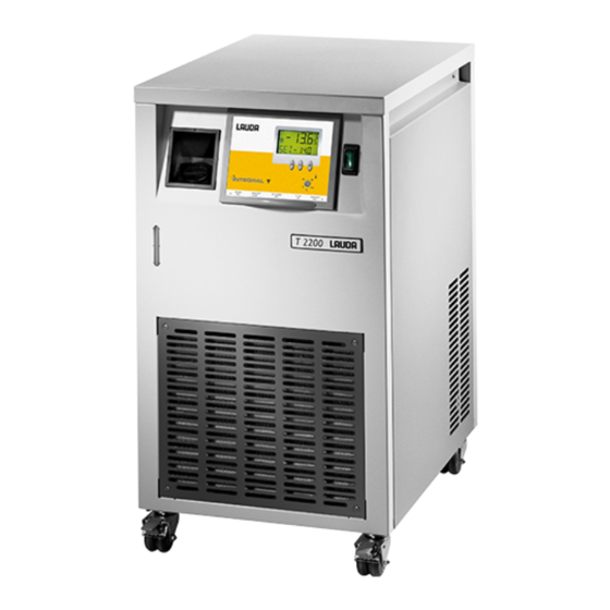
 Integral T T 1200 (W), T 2200 (W), T 4600 (W), T 7000 (W), T 10000 (W) Process thermostats Read the operating manual before starting all work.
Page 3
T 1200 (W), T 2200 (W), T 4600 (W), T 7000 (W), T 10000 (W) Translation of the original operating instructions LAUDA DR. R. WOBSER GMBH & CO. KG release 01/2019 i Pfarrstraße 41/43 replaces release 05/2017 h, 09/2016 g7, 04/2016 g6, 97922 Lauda-Königshofen...
Page 5
Integral T process thermostats Prefixed safety notes Before you operate the equipment please read carefully all the instructions and safety notes. If you have any questions please phone us! Follow the instructions on setting up, operation etc. This is the only way to exclude incorrect operation of the equipment and to ensure full warranty protection.
Integral T process thermostats Contents SAFETY NOTES ............................9 ......................... 9 ENERAL SAFETY NOTES ..........................9 THER SAFETY NOTES ........................... 11 CONFORMITY BRIEF INSTRUCTIONS ........................... 12 CONTROL AND FUNCTIONAL ELEMENTS ..................14 EQUIPMENT DESCRIPTION ........................15 ........................ 15 NVIRONMENTAL CONDITIONS ..........................
Page 7
Integral T process thermostats 7.6.3 Programmer level (PGM) ......................38 7.6.3.1 Example of programme ......................39 7.6.3.2 Menu structure .......................... 39 7.6.3.3 Programme selection and start ....................40 7.6.3.4 Terminate, pause, continue the programme ................41 7.6.3.5 INFO submenu .......................... 42 7.6.3.6 Edit submenu ..........................
Page 8
Integral T process thermostats 8.6.3 Decalcifying the cooling water circuit ................... 92 ........................94 ISPOSAL INFORMATION ..................94 ERVICE AND ORDERING REPLACEMENT PARTS TECHNICAL DATA ..........................95 ACCESSORIES ............................. 101 Special symbols: This symbol is used where there may be injury to Danger: personnel through incorrect handling.
Safety notes General safety notes A LAUDA process thermostat is intended for heating or cooling and circulating liquids. This leads to hazards through high or low temperatures, excess pressures, fire and the general hazards through the use of electrical energy.
Page 10
Integral T process thermostats Classification in accordance with EMC requirements of DIN EN 61326-1 Device Immunity Emissions class Customer power supply Process thermostat Only for EU Integral T Type 2 in Emissions Class B single-phase and accordance with in accordance with Domestic connection value triple-phase DIN EN 61326-1...
The device complies with the basic health and safety requirements outline in the Directives listed below. Machinery Directive 2006/42/EC EMC Directive 2014/30/EU LAUDA DR. R. WOBSER GMBH & CO. KG – Pfarrstraße 41/43 - 97922 Lauda-Königshofen - Germany The device does not fall under Pressure Equipment Directive 2014/68/EU because the device is only classified as high as Category 1 and is covered by the Machinery Directive.
Integral T process thermostats Brief instructions These brief instructions are intended to provide you with a quick introduction to operating the equipment. For reliable operation of the thermostats it is however absolutely essential that you read carefully the full Operating Instructions and observe the safety notes! 1.
Page 13
Integral T process thermostats 7. Equipment setup Section 7.6.3 Section 7.6.4 Section 7.6.5 Section 7.6.6 The Parameter menu includes a default function ( Section 7.6.4.7) which produces a basic adjustment of nearly all functions and permits basic operation with internal control. Brief instructions YAWE 0026 21/01/2019/...
Integral T process thermostats Control and functional elements 7. Exit and entrance cooling water connections R3/4” 1. Rating label (only water cooled devices W). 2. Bypass adjustment 8. Level indication ( 6.2) 3. Pump connections 9. Filler opening for heat transfer liquid 4.
Integral T process thermostats Equipment description Environmental conditions The operation of the thermostats is only allowed under the following conditions as specified in DIN EN 61010-2-010:2003 and DIN EN 61010-1:2001: Indoor use. Altitude up to 2000 m above sea level. ...
Integral T process thermostats Bath, pump The relatively small bath contains the functional elements such as tubular heater, pump for external circulation, evaporator or pump for internal circulation on units from T 4600, temperature probe and low-level sensor. In addition there is a larger expansion volume which is only partially thermally active. The front of the equipment carries a level indicator.
(with reduced reaction on the mains supply), the automatic compressor control, and the cooling control which operates with low-noise solenoid valves. The LAUDA proportional cooling principle permits control in the cooling range without any energy- wasting counter-heat.
Integral T process thermostats Interfaces Connectors for standby contact input, fault (alarm) contact output, analogue inputs and outputs, external Pt100 and serial RS 232/RS 485 interfaces are accessible from below after swinging out the control unit. The control unit can be folded out to Position 2 in order to connect the sockets and then be folded back to Position 1.
Integral T process thermostats Options The options installed in the device are to be recognized by a label next to the type designation plate. 4.9.1 Option enlarged temperature range to 150 °C Only at T 7000 (W) and T 10000 (W)! The device is modified so that the upper limit of the working temperature range is expanded from 120 °C to 150 °C.
Integral T process thermostats Preparations Assembly and setting up It is advisable to set up the equipment so that the control unit is towards the front and that the ventilation for the refrigeration unit, especially on equipment with air-cooled condenser, (ventilation grille in lower part) is not impeded.
Page 22
Integral T process thermostats Water-cooled version The heat of condensation and the motor heat are dissipated through a water-cooled counter flow heat exchanger. Connect up the hoses. The connection for inlet (from water tap) and outlet (to drain) are located on the back of the equipment at the bottom. Inlet on the left, outlet to drain on the right, looking on the back of the equipment.
Integral T process thermostats Filling and connection of external circuit Fill the equipment with heat transfer liquid to suit the operating temperature. Note: The T 4600 (W), 7000 (W) and 10000 (W) should not be filled with pure water, but only with Kryo 30 or a water-glycol mixture (minimum 70 % : 30 %)! When using water as heat transfer liquid at T 1200 (W) and T 2200 (W) please make sure that there are no operating temperatures below 5 °C in the outflow.
Integral T process thermostats With external circuits at a higher level, even with a closed circuit, the external volume may drain down when the pump is stopped and air enters the thermostating circuit; this may result in overflowing of the storage bath! Use only hydraulic closed consumers.
Integral T process thermostats Heat transfer liquids, cooling water and hoses a) Approved heat transfer liquids Working Chemical LAUDA Viscosity Viscosity Flash Container size (kin) (kin) temperature characterizatio designation @ 20 °C temperature point Catalogue number range from °C mm²/s mm²/s...
Page 26
Integral T process thermostats b) Cooling water Certain requirements are placed on the cooling water with regard to purity. Depending on the cooling water contamination, a suitable method of purification and/or treatment of the water must be employed. The condenser and the complete cooling water circuit can become blocked, damaged and leaky due to unsuitable cooling water.
Page 27
Integral T process thermostats Risk to the environment due to oil contamination of the cooling water circuit With a leaky condenser there is the danger that refrigerating machine oil from the refrigerant circuit of the cooling thermostat can pass into the cooling water. Follow all the legal requirements and the regulations of the water supply utility which apply at the point of use.
Page 28
Integral T process thermostats Metal hose insulated, temperature range -50 – 150 °C; maximum working pressure 10 bar Type length cm nominal width Screw connection Cat. No. MTK 100 DN 20 G ¾ LZM 075 MTK 200 DN 20 G ¾ LZM 076 MTK 101 DN 25...
Integral T process thermostats Starting up Connection to the supply Compare the information on the equipment label with the supply details. Connect the equipment only to a socket with a protective earth (PE) connection. No warranty when the equipment is connected to the wrong supply! ...
Page 30
Integral T process thermostats The display only appears if function "Manual Start" is activated which means that every time the unit was OFFline, it has to be started with the key ( Section 7.6.4.2). In case "Auto start" is activated, the following display is shown immediately after unit has been switched Attention: If the key pad is locked (KEY-function) the KEY-function must be switched OFF first.
Integral T process thermostats If necessary add more bath liquid to replace the amount pumped out to fill the external circuit. » If the low-level indication appears. A dual tone sounds. The fault triangle is flashing. ...
Integral T process thermostats 7.3.2 Key inhibit (KEY) Key operation can be inhibited with the KEY function in order to prevent unauthorised alteration of the equipment settings via the keys. Press key and hold it down. Within 4 sec press also and hold it down.
Integral T process thermostats LC-Display Standby symbol Heating symbol Line 1 Line 1 shows external actual temperature. T Line 1 shows internal actual temperature TI (outflow temperature). Line 2 Cooling symbol Error symbol Starting up 21/01/2019 / YAWE 0026...
Integral T process thermostats 7.5.1 Setpoint selection (Level 0) Press keys until SET (Setpoint) appears. Enter, display is flashing. Enter setpoint with both keys ( Section 7.3.1). Display is flashing 4 s new value is entered automatically, or ...
Integral T process thermostats When external Pt100 is not connected. Connection of the external Pt100 to Lemo socket 10S: Current path Voltage path Pt100 Voltage path DIN EN 60751 Current path 4-pin Lemosa plug for Pt100 connection (Cat. No. EQS 022). ...
Integral T process thermostats Level 1 see ( 7.5). 7.6.1 Standby (ON) Three operating modes can be selected, Display is flashing. 0 = equipment on standby: pump(s), heating, refrigeration unit OFF. Control unit and displays are operating. The symbol in the display on the left is alight.
Integral T process thermostats No Pt100 is connected to socket 10S and no standard analogue signal is switched on (66S), the display shows FAIL when an attempt is made to activate external control. Reset with key. 7.6.3 Programmer level (PGM) The programmer function of the units permits storage of 5 temperature-time programmes.
Integral T process thermostats 7.6.3.1 Example of programme Cooling-down time depending on thermostat volume, external system etc. Original programme example Edited programme example Segment Temperature Time Segment Temperature Time °C °C 30,0 30,0 50,0 50,0 50,0 20 70,0 20 ...
Integral T process thermostats Section 7.6.3.4 Section 7.6.3.4 Section 7.6.3.5 Section 7.6.3.6 7.6.3.3 Programme selection and start Press the key to go to the submenu of the programmer function. Starting up YAWE 0026 / 21/01/2019...
Integral T process thermostats Press the key to go to programme selection. Press the keys to go to the programmes P 1, P 2 –. P 5, or backwards. Key starts the programme. Display changes to basic menu (level 0) and shows e.
Integral T process thermostats I. e. pressing the key terminates the programme run. The final setpoint is retained. You are at the beginning of the start menu. The programme can be started from the beginning (segment ( Section 7.6.3.3) or you can exit the menu with END (...
Page 43
Integral T process thermostats With this key from PAUSE or CONt to the INFO menu. On pressing this key, line 2 of the display shows the number of the programme selected. Line 2 shows programme 5. Pressing the key changes the display to the current programme LOOP.
Integral T process thermostats You can exit the INFO submenu in END. 7.6.3.6 Edit submenu Here there are the following functions: Select programme. Input a programme. Show the programme data of a stored programme and alter the segment data. ...
Page 45
Integral T process thermostats Press key to enter. Input of a programme: ( Programming example 7.6.3.1) This display appears if the programme storage position is empty; i.e. no segment has been defined. Increments the number of segments by one each time until the required number of segments appears.
Page 46
Integral T process thermostats Segment target temperature Segment number Segment time in minutes Press key. Segment target temperature flashes with brief OFF period. Press again. Segment target temperature flashes in input mode (longer OFF time). Input the target temperature. ...
Page 47
Integral T process thermostats Input the segment time 0 – 999 min. Enter the value, or it is entered automatically as above. Click forward to end. Terminates input mode for segment 1. Click forward to segment 2. Further inputs as for segment 1 etc.
Page 48
Integral T process thermostats Display of a stored programme and alteration of the segment data: Start as described under Edit, programme selection, then scroll with through the segment data. With select Edit; the temperature value blinks briefly. Continue as for programme input. Adding or inserting a new segment: Both alterations increase the number of segments! Adding:...
Page 49
Integral T process thermostats Inserting: Inserting new segments. For inserting one or more segments, proceed as described above. Example: After segment 2 it is requested to enter a further segment. Then using the key, select the segment after which a new segment has to be inserted.
Page 50
Integral T process thermostats Deleting a segment: Deleting the last segment: In the Edit submenu clock forward until the display shows DEL. The display shows the final segment number of the programme. Press key twice to delete the final segment. ...
Page 51
Integral T process thermostats The display shows the new final segment number. The display shows DEL AII instead of DEL 0. This allows deletion of the entire programme. This operation is recommended before input of a new programme at a programme storage position which has already been used, before input of the segment number with NEW.
Integral T process thermostats 7.6.4.1 Serial interface parameters / Remote control Selection whether RS 232 or RS 485 is being set. On RS 485 the device address has to be set from 1 to On RS 232 the display shows immediately the selection menu for baud rate.
Integral T process thermostats When communication between thermostat and FBT is interrupted there is a fault message and acoustic signal. This is also the case when the FBT is switched off. Unit is switched off as is in case of fault. ...
Integral T process thermostats 7.6.4.3 Outflow temperature limit High limit (TiH) The temperature set here limits the outflow temperature. Especially with external control this limitation avoids the undesirable permanent switch-off through the safety circuit (overtemperature) during the start-up phase. Low limit (TiL) ...
Integral T process thermostats 7.6.4.4 Neutral contact function OUT determines the function that is reported through the neutral contact. 0 = Overall fault (default setting) ( 7.6.4.7) 1 = Tolerance range monitoring ( 7.6.4.5). 7.6.4.5 Tolerance range contact With WIN (Window) a tolerance range can be chosen.
Integral T process thermostats Calibrating the internal Pt100 (outflow sensor) Measure the outflow temperature with the reference probe at the pump outlet in the liquid stream. Press approx. 4 sec. Input the corrected value. Calibrating the external Pt100 (external sensor) ...
Integral T process thermostats The display shows OK. Menu end “Parameter“ 7.6.4.8 Leads to PARA . . at level 1. Starting up YAWE 0026 / 21/01/2019...
Integral T process thermostats 7.6.5 Analogue interface level (ANA) The equipment is provided with two standard analogue signal inputs and 3 outputs. Each input and output can be set to the standard signals 0 - 10 V, 0 - 20 mA or 4 - 20 mA. The signals are connected to a 6-pin plug (66S) according to NAMUR NE 28.
Page 60
Integral T process thermostats Accuracy of the inputs and outputs after calibration is better than ± 0,1 % full scale Resolution of the outputs Temperature < 0,01 % of the range however not < 0.01 °C controller output Y 0.1 % Pressure 0.1 bar...
Page 61
Integral T process thermostats Analogue setpoint input is switched on, with current input (I) configuration. With voltage the display shows AIS U. Scroll to AIE pressing the key leads to submenu setpoint, “Analogue inputs” ( Section 7.6.5.1). ...
Page 62
Integral T process thermostats leads to the submenu “Analogue outputs”. Pressing ( Section 7.6.5.2). CAL = calibration of inputs and outputs at 0 and 10 V or 0/ 4 and 20 mA. leads to the submenu “Calibration”. Pressing (...
Integral T process thermostats 7.6.5.1 Submenu Analogue inputs From AIS scroll to USE = here the input setpoint can be switched (ON/OFF). Enter required status with Starting up 21/01/2019 / YAWE 0026...
Page 64
Integral T process thermostats Type = input signal type; voltage 0-10 V (U) or current 0-20 mA (4- 20 mA) (I). If a current range has been selected there is also a request whether range 0-20 mA or range 4-20 mA is required.
Page 65
Integral T process thermostats MAX = maximum temperature in °C. For determining the temperature range to which the current or voltage range has to be assigned. Example: 0 – 10 V is to correspond to –50 – 150 °C MIN = -50;...
Integral T process thermostats 7.6.5.2 Submenu Analogue outputs From A01 scroll to USE = here the analogue output 1 (or, depending on previous steps, output 2 or output 3) can be switched ON and OFF. Enter required status with Starting up YAWE 0026 / 21/01/2019...
Page 67
Integral T process thermostats Type = output signal type; Voltage 0 – 10 V (U) or Current 0 – 20 mA (4 – 20 mA) (I). If a current range has been selected there is also a request whether range 0 – 20 mA or range 4 – 20 mA is required.
Page 68
Integral T process thermostats MAX = maximum temperature in °C (pressure or electrical output). For determining the temperature range to which the current or voltage range has to be assigned. MODE = operating mode; assignment of signal source to output.
Integral T process thermostats 7.6.5.3 Submenu Calibration (ANA) In order to avoid undesirable operating conditions only the selected channel is switched on during calibration. All others are switched off. After calibration has been completed the previous status (inputs/ outputs ON/ OFF) is restored. Starting up 21/01/2019 / YAWE 0026...
Page 70
Integral T process thermostats From CAL . . scroll to C In = calibrate (C); Input (In); S.I = setpoint; current signal (I). S.U = setpoint; voltage signal (U). E E.I = external temperature input (E); current signal (I).
Page 71
Integral T process thermostats Calibrating the inputs Apply the voltage or current for the appropriate range limits (0 V, 10 V, 0 mA, 20 mA). Deviations up to approx. 10 % of range can be corrected. The calibration values remain stored! ...
Page 72
Integral T process thermostats after approx. 4 sec. the second point. Take current reading on the meter and set it with e.g. 1300 = 1.3 mA. Take current reading on the meter and set it with e.g. 1991 = 19.91 mA. ...
Integral T process thermostats Take voltage reading on the meter and set it with After calibration has been completed this display appears again. Back to the menu "Analogue interface CAL". 7.6.6 Control parameter level With internal control (outflow control): Starting up 21/01/2019 / YAWE 0026...
Page 74
Integral T process thermostats With external control switched on: Pressing scrolls from REG . . to the input for the control parameters. With internal control (CON I) With internal control (CON I) select here the proportional band Xp for the outflow controller. Input range 0.1 –...
Page 75
Integral T process thermostats Select here the reset time TN for the outflow controller. Input range 1 - 200 sec. 200 is followed by OFF, i.e. the integral function of the controller is switched off, the controller operates as a proportional controller with permanent control offset.
"HyperTerminal" is no longer part of the operating system in Windows Vista, Windows 7 and Windows 8. With the LAUDA software "Wintherm Plus" (catalogue number LDSM2002) the RS 232 interface can be addressed. In the internet there are terminal programs available as freeware. These programs offer similar functions as "HyperTerminal"...
Integral T process thermostats Protocol: The interface operates with 1 stop bit, no parity bit and 8 data bits. Transfer rate either 2400, 4800, 9600 (factory setting) or 19200 baud as selected. The RS 232 interface can be operated with or without hardware handshake, (RTS/CTS).
Page 78
Integral T process thermostats An RS 485 bus always requires bus termination in the form of a termination network which ensures a defined rest status in the high-resistance phases of bus operation. The bus termination is as follows: This termination network is usually incorporated on the PC plug-in card (RS 485). Protocol: ...
Integral T process thermostats 7.7.3 Write commands (data commands to the thermostat Command Explanation OUT_SP_00_XXX.XX Setpoint transfer with max. 3 digits before decimal point and max. 2 decimal digits behind. OUT_SP_04_XXX.XX TiH outflow temperature high limit. OUT_SP_05_XXX.XX TiL outflow temperature low limit. Setting of control parameter Xp for controller (0.1 –...
Integral T process thermostats For ”_“ use also ” ” (blank character). Response from thermostat “OK” or in case of error ”ERR_X“ (RS 485 interface e.g.. “A015_OK” or in case of error ”A015_ERR_X”.). In different dates for one parameter (except for set point) are continuously transmitted to the thermostat due to bugs, this can lead to the destruction of the storage location in the thermostat.
Page 81
Integral T process thermostats STAT Read error diagnosis response: XXXXXXX X = 0 no error, X = 1, 2, 3 error. 1. Char. = error (Exx). 2. Char. = pump error 0 = OK / 1 = pump 1 / 2 = pump 2 / 3 = both pumps error. 3.
INTEGRAL XT, INTEGRAL T and WK/WKL units can be programmed with the aid of the National ® Instruments program development tool LABVIEW (http://sine.ni.com/apps/we/nioc.vp?cid=1381&lang=US). In order to make program operation possible on the RS 232/ RS 485 interface, LAUDA provides drivers ® specially designed for LABVIEW which can be downloaded free of charge under www.lauda.de.
Integral T process thermostats Warning and safety functions 7.8.1 Overtemperature protection and testing The units are designed for operation with non-flammable and flammable liquids to EN 61010-2-010. Set the overtemperature switch-off point. Recommended setting 5 °C above the setpoint. ...
If there is any irregularity when testing the safety devices, switch off the equipment immediately and pull out the mains plug! Have the equipment checked by LAUDA Service Constant Temperature Equipment! Starting up YAWE 0026 / 21/01/2019...
Integral T process thermostats 7.8.3 Pump motor monitoring In case of pump motor overload or a blockage, the heating, the pump and the refrigeration system are switched off. » A double signal tone sounds. The display PUMP 1 appears and the fault triangle is flashing.
Integral T process thermostats 7.8.5 Floating contact connection "Combination fault" 12N (Alarm out) This function is only available if in the parameter menu OUT is set to 0 ( Section 7.6.4.3). 3-pin flange connector to NAMUR recommendation NE 28. ...
Page 87
Integral T process thermostats Message Explanation Can not write to data memory. Data memory contains data errors. Break or short-circuit of temperature sensor. Temperature measurement circuit does not respond. Measurement circuit for analogue inputs does not respond. Message from control system: temperatures of safety and control systems not identical. Message from safety system: temperatures of safety and control systems not identical.
“Refrigerating Plants, Heating Pumps and Cooling Systems” (Unfallverhütungsvorschriften BGV D4) as well as “Electrical Installations and Operating Material” (BGV A2)! LAUDA process thermostats are largely maintenance-free. If the heat transfer liquid becomes dirty it has to be replaced. Maintenance YAWE 0026 / 21/01/2019...
Integral T process thermostats Servicing intervals Mandatory for initial operation and before any System part longer unsupervised Chapter Comment operation, then with recommended frequency Complete device External condition of the Monthly device Heat transfer liquid Analysis of heat transfer Half-yearly (and as required) (...
Page 90
Integral T process thermostats T 2,5 A, 5x20 UL 514-A/B Circuit board UL 514-A/B (power supply) carries an instrument fuse T 2,5 A; 5x20. Cat. No. EEF 025. This is accessible after opening up the unit. The panels to the left and right of the electrical section may have to be removed.
Integral T process thermostats 8.5.1 Dismantling the control unit Turn the screw for the locking tab anticlockwise up to the stop. Swing out the control unit and pull it out downwards. Carefully disconnect the connectors! A1/X61 A1/X6 A1/X20 Disconnect connector A1/X61 and A1/X20. Disconnect connector A1/X6.
Integral T process thermostats Maintenance of the refrigeration unit 8.6.1 Air-cooled condenser The refrigeration unit is largely maintenance-free. If the equipment is operating in a dusty atmosphere the condenser of the refrigeration unit has to be cleaned every 4 to 6 months or more frequently.
Page 93
Continue the pump stage until most of the foamy reaction, usually at the start, has decayed. Generally, this is achieved after about 20 to 30 minutes. Decalcifier LAUDA article number: LZB 126 (5 kg) When handling the chemicals, the safety information and the instructions for use on the package are to be followed.
If the equipment has to be returned to the factory, please ensure that it is carefully and properly packed. LAUDA accepts no responsibility for damage due to unsatisfactory packing. When ordering replacement parts, please state the serial number (rating label); this avoids queries and incorrect supply.
Integral T process thermostats Technical Data The figures have been determined according to DIN 12876. T 1200 T 1200 W T 2200 T 2200 W -25 – 120 (-25 – 150 option enlarged temperature range) Working temperature range °C 5 – 40 Ambient temperature range °C Setting resolution...
Page 96
Integral T process thermostats T 1200 T 1200 W T 2200 T 2200 W Heater power rating / power 2.25 / 2.7 2.25 / 2.7 2.25 / 3.1 2.25 / 3.1 consumption @ 230 V; 50 Hz Heater power rating / power 2.25 / 3.1 2.25 / 3.1 consumption @ 230 V;...
Page 97
Integral T process thermostats T 4600 T 4600 W T 7000 T 7000 W T 10000 T 10000 W -30 – 120 (-30 – 150 option enlarged temperature range) Working temperature range °C 5 – 40 Ambient temperature range °C Setting resolution Temperature measurement Pt100 outflow temperature and connection for external Pt100 via Lemo...
Page 98
Integral T process thermostats T 4600 T 4600 W T 7000 T 7000 W T 10000 T 10000 W Heater power rating / power consumption 6.0 / 8.5 6.0 / 8.3 @ 400 V; 3/PE; ~50 Hz Heater power rating / power consumption 6.0 / 11.5 6.0 / 11.2...
Page 99
Integral T process thermostats Pump characteristics: Option high-power pump max. 5.5 bar ( Section 4.9.2). T 1200 (W), T 2200 (W), T 4600 (W) By-pass closed By-pass max. 2.5 bar By-pass max. 1.5 bar Option low-pressure pump max. 1 bar (...
Page 100
Integral T process thermostats Refrigerant and filling quantity The device contains fluorinated greenhouse gases. Unit T 1200 T 1200 W T 2200 T 2200 W Refrigerant R-404A R-404A R-404A R-404A maximum filling quantity 3922 3922 3922 3922 (100a) equivalent Unit T 4600 (W) T 7000 (W) T 10000...
Integral T process thermostats Accessories Accessories Catalogue number 4-way manifold for pump outflow and return; each connection with separate shut-off. for units with 3/4" pipe connections / 3/4" hose VT 2 LWZ 010 for units with 3/4" pipe connections / 1/2" hose VT 3 LWZ 022 for units with 1-1/4"...
Page 105
/ Personne responsable Hiermit bestätigen wir, daß nachfolgend aufgeführtes LAUDA-Gerät (Daten vom Typenschild): We herewith confirm that the following LAUDA-equipment (see label): Par la présente nous confirmons que l’appareil LAUDA (voir plaque signalétique): Serien-Nr. Type / Type Serial no. / No. de série:...
Need help?
Do you have a question about the Integral T 1200 and is the answer not in the manual?
Questions and answers