Table of Contents
Advertisement
Instruction Manual
AC Servo Motor and Driver
MINAS A4P Series
•Thank you for buying and using Panasonic AC Servo Motor and Driver, MINAS A4P Series.
•Read through this Instruction Manual for proper use, especially read "Precautions for Safety" ( P.8
to 11) without fail for safety purpose.
•Keep this Manual at an easily accessible place so as to be referred anytime as necessary.
DV0P4490
Advertisement
Chapters
Table of Contents

Related Manuals for Panasonic MINAS A4P Series


Summary of Contents for Panasonic MINAS A4P Series
- Page 1 AC Servo Motor and Driver MINAS A4P Series •Thank you for buying and using Panasonic AC Servo Motor and Driver, MINAS A4P Series. •Read through this Instruction Manual for proper use, especially read "Precautions for Safety" ( P.8 to 11) without fail for safety purpose.
-
Page 2: [Before Using The Products]
Content [Before Using the Products] Safety Precautions ... 8 Maintenance and Inspection ... 12 Introduction... 14 Outline ... 14 On Opening the Package ... 14 Check of the Driver Model ... 14 Check of the Motor Model ... 15 Check of the Combination of the Driver and the Motor ... 16 Parts Description ... - Page 3 List of Servo Parameter ... 58 List of 16-bit Positioning Parameters ... 73 List of 32-bit Positioning Parameters ... 77 List of Step Parameters ... 77 Setup of Torque Limit ... 78 How to Use the Console ... 80 Setup with the Console ... 80 Initial Status of the Console Display (7 Segment LED) ...
- Page 4 Timing Chart ... 132 Operation Timing after Power-ON ... 132 When an Error (Alarm) Has Occurred (at Servo-ON Command) ... 133 When an Alarm Has Been Cleared (at Servo-ON Command) ... 134 Servo-ON/OFF Action While the Motor Is at Stall (Servo-Lock) ... 135 Servo-ON/OFF Action While the Motor Is in Motion ...
- Page 5 [Supplement] page Conformity to EC Directives and UL Standards ... 176 Options ... 180 Recommended components ... 191 Dimensions (Driver)... 192 Dimensions (Motor) ... 195 Permissible Load at Output Shaft ... 210 Motor Characteristics (S-T Characteristics) ... 211 Motor with Gear Reducer ... 217 Dimensions/Motor with Gear Reducer ...
-
Page 7: Table Of Contents
[Before Using the Products] Safety Precautions ... 8 Maintenance and Inspection ... 12 Introduction ... 14 Outline ... 14 On Opening the Package ... 14 Check of the Driver Model ... 14 Check of the Motor Model ... 15 Check of the Combination of the Driver and the Motor ... 16 Parts Description ... -
Page 8: Safety Precautions
Safety Precautions Observe the following precautions in order to avoid damages on the machinery and injuries to the operators and other personnel during the operation. • In this document, the following symbols are used to indicate the level of damages or injuries which might be incurred by the misoperation ignoring the precautions. - Page 9 Do not place combustibles near by the motor, driver and regenera- tive resistor. Failure to observe this in- struction could result in fire. Ground the earth terminal of the motor and driver without fail. Failure to observe this in- struction could result in electrical shocks.
-
Page 10: Safety Precautions
Safety Precautions Do not hold the motor cable or motor shaft during the transporta- tion. Failure to observe this instruction could result in injuries. Never run or stop the motor with the electro-magnetic contactor installed in the main power side. Failure to observe this instruction could result in breakdowns. - Page 11 Use the motor and the driver in the specified combination. Failure to observe this instruction could result in fire. Use the eye bolt of the motor for transportation of the motor only, and never use this for transporta- tion of the machine. Failure to observe this instruction could result in injuries and breakdowns.
-
Page 12: Maintenance And Inspection
Maintenance and Inspection • Routine maintenance and inspection of the driver and motor are essential for the proper and safe operation. Notes on Maintenance and Inspection 1) Turn on and turn off should be done by operators or inspectors themselves. 2) Internal circuit of the driver is kept charged with high voltage for a while even after power-off. - Page 13 Guideline for Parts Replacement Use the table below for a reference. Parts replacement cycle varies depending on the actual operating conditions. Defective parts should be replaced or repaired when any error have occurred. Disassembling for inspection and repair should be carried out only by authorized dealers or service company.
-
Page 14: Introduction
1ø 3ø F.L.C 1.3A 1.2A Freq. 50/60Hz 0~333.3Hz Power 100W 5 to 6 8 to 9 Current rating Power supply Symbol Specifications Single phase, 100V Single phase, 200V 3-phase, 200V Single/3-phase, 100A 200V 150A P0511 0001Z e.g.) : Lot number... -
Page 15: Check Of The Motor Model
Check of the Motor Model Contents of Name Plate Model Rated input voltage/current Rated output Rated rotational speed Model Designation M S M D 5 A Z S 1 S 1 to 4 Symbol Type Ultra low inertia MAMA (100W to 750W) Low inertia MQMA (100W to 400W) -
Page 16: Check Of The Combination Of The Driver And The Motor
Introduction Check of the Combination of the Driver and the Motor This drive is designed to be used in a combination with the motor which are specified by us. Check the series name of the motor, rated output torque, voltage specifications and encoder specifications. Incremental Specifications, 2500P/r <Remarks>... - Page 17 Absolute/Incremental Specifications, 17-bit <Remarks> Do not use in other combinations than those listed below. Power Motor supply series rotational speed Single phase, MAMA 200V Ultra low 3-phase, inertia 200V Single phase, 100V MAMA Single phase, inertia 200V Single phase, 100V MSMD Single phase, inertia...
-
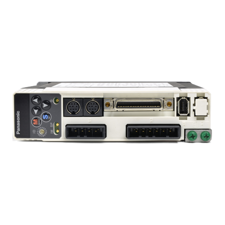
Page 18: Parts Description
Parts Description Driver • A and B-frame Velocity monitor check pin (SP) Torque monitor check pin (IM) Check pin (G : GND) Connector Main power Connector, CN X1 input terminals (L1,L2) for power input connection Control power 04JFAT-SAXGF input terminals (JST) (L1C, L2C) Terminals... - Page 19 • E and F-frame Check pin (G : GND) Main power input terminals (L1,L2,L3) Control power input terminals (r, t) Terminals for external regenerative resistor (P, B1, B2) Terminals for motor connection (U,V,W) Screws for earth (x2) e.g.) : MEDDT7364P (3-phase, 200V, 2.0kW : E-frame) Check pin (G : GND) Main power input terminals...
-
Page 20: Motor
Parts Description Motor • MSMD 50W to 750W • MAMA 100W to 750W • MQMA 100W to 400W Connector for brake cable (Only applicable to the motor with electromagnetic brake) e.g.) : Low inertia type (MSMD series, 50W) • MSMA 1.0kW to 5.0kW •... -
Page 21: Console
Console Main Body Connector Cable <Note> Console is an option (Part No.: DV0P4420). Display/Touch panel Mode Switching Button Press this to switch 7 kinds of mode. 1) Monitor mode 2) Teaching mode • Target position settings established by teaching • Test operation 3) Parameter setup mode 4) EEPROM write mode The data for the parameters is set after the mode has been switched to the parameter setup mode. -
Page 22: Installation
How to Install Install the driver and the motor properly to avoid a breakdown or an accident. Driver Installation Place 1) Indoors, where the products are not subjected to rain or direct sun beams. The products are not water- proof. 2) Where the products are not subjected to corrosive atmospheres such as hydrogen sulfide, sulfurous acid, chlorine, ammonia, chloric gas, sulfuric gas, acid, alkaline and salt and so on, and are free from splash of inflammable gas, grinding oil, oil mist, iron powder or chips and etc. - Page 23 Mounting Direction and Spacing • Reserve enough surrounding space for effective cooling. • Install fans to provide uniform distribution of temperature in the control panel. • Observe the environmental conditions of the control panel described in the next page. 40mm 10mm or more more...
-
Page 24: Motor
How to Install Motor Installation Place Since the conditions of location affect a lot to the motor life, select a place which meets the conditions below. 1) Indoors, where the products are not subjected to rain or direct sun beam. The products are not water- proof. - Page 25 Stress to Cables 1) Avoid a stress application to the cable outlet and connecting portion by bending or self-weight. 2) Especially in an application where the motor itself travels, fix the attached cable and contain the extension junction cable into the bearer so that the stress by bending can be minimized. 3) Take the cable bending radius as large as possible.
-
Page 26: Console
How to Install Console Installation Place 1) Indoors, where the products are not subjected to rain or direct sun beam. The products are not water- proof. 2) Where the products are not subjected to corrosive atmospheres such as hydrogen sulfide, sulfurous acid, chlorine, ammonia, chloric gas, sulfuric gas, acid, alkaline and salt and so on, and are free from splash of inflammable gas, grinding oil, oil mist, iron powder or chips and etc. - Page 27 [Preparation] System Configuration and Wiring ... 28 Overall Wiring (Connecting Example of C-frame, 3-phase) ... 28 Overall Wiring (Connecting Example of E-frame) ... 30 Driver and List of Applicable Peripheral Equipments ... 32 Wiring of the Main Circuit (A to D-frame) ... 34 Wiring of the Main Circuit (E and F-frame)...
-
Page 28: System Configuration And Wiring
System Configuration and Wiring Overall Wiring (Connecting Example of C-frame, 3-phase) • Wiring of the Main Circuit (see P.32, 33 and 177.) Circuit Breaker (NFB) Use the circuit breaker matching capacity of the power source to protect the power lines. (see P.177 , 178.) Noise Filter (NF) Prevents external noise from the power... - Page 29 (Connection to host controller) • Wiring to Connector, CN X6 (Connection to encoder) • Wiring to Connector, CN X7 (Connection to external scale) DC Power supply for brake DC24V (to be supplied by customer) [Preparation] ® " Junction cable for encoder...
-
Page 30: Overall Wiring (Connecting Example Of E-Frame)
Thermal fuse and thermostat are built in to the regenerative resistor (Option). If the thermal fuse is activated, it will not resume. • Connection with input power supply <Remarks> Before turning the power supply on, check whether the input voltage is correct. - Page 31 Short bar From a top U-phase V-phase W-phase Junction cable for brake DC Power supply for brake DC24V (to be supplied by customer) : High voltage • Wiring to Connector, CN X4 (option) (Connection to PC or host controller) • For manufacturers' use...
-
Page 32: Driver And List Of Applicable Peripheral Equipments
System Configuration and Wiring Driver and List of Applicable Peripheral Equipments Required Applicable Rated Power Driver Voltage (at the rated motor output approx. MSMD Single –100W 0.4kVA phase, approx. MQMA 100V 100W 0.4kVA approx. MSMD –200W 0.5kVA MADD approx. Single 100W 0.3kVA MQMA... - Page 33 Required Applicable Rated Power Driver Voltage (at the rated motor output approx. MGMA 2.0kW 3.8kVA MDMA MHMA approx. 3.0kW 4.5kVA MSMA MGMA MDMA 3- phase, approx. MFDD MHMA 200V 4.0kW 6kVA MSMA approx. MFMA 6.8kVA 4.5kW approx. MGMA 7.5kVA MDMA approx.
-
Page 34: Wiring Of The Main Circuit (A To D-Frame)
Green yellow Motor Ground resistance : 100Ω max. For applicable wire, refer to P.B14 and B15. DC power supply for brake Surge absorber Fuse (5A) • Check the name plate of the driver for power specifications. • Provide a circuit breaker, or a leakage breaker. The leakage breaker to be the one designed for "Inverter"... -
Page 35: Wiring Diagram
Compose the circuit so that the main circuit power will be shut off when an error occurs. In Case of Single Phase, 100V (A and B-frame) Power supply Single phase, 100V Built-in thermostat of an external regenerative resistor (light yellow) -
Page 36: Wiring Of The Main Circuit (E And F-Frame)
Green yellow Motor Ground resistance : 100Ω max. For applicable wire, refer to P.B14 and B15. DC power supply for brake Surge absorber Fuse (5A) • Check the name plate of the driver for power specifications. • Provide a circuit breaker, or a leakage breaker. The leakage breaker to be the one designed for "Inverter"... -
Page 37: How To Connect
Compose the circuit so that the main circuit power will be shut off when an error occurs. In Case of 3-Phase, 200V (E and F-frame) +10% Power supply 3-phase, 200V –15% Built-in thermostat of an external regenerative resistor (light yellow) -
Page 38: Wiring To The Connector, Cn X6 (Connection To Encoder)
System Configuration and Wiring Wiring to the Connector, CN X6 (Connection to Encoder) Tips on Wiring Power supply Encoder 30cm or more Motor 20m max. Connector Junction cable 20m max. Junction cable Cannon plug 20m max. Encoder junction cable Encoder side Driver side connector CN X6... - Page 39 • MSMA 1kW to 5kW • MDMA 1kW to 5kW • MHMA 500W to 5kW • MFMA 400W to 4.5kW • MGMA 900W to 4.5kW motor Wiring Diagram In case of 17-bit absolute/incremental encoder • MSMD 50W to 750W • MAMA 100W to 750W •...
-
Page 40: Wiring To The Connector, Cn X7 (Connection To External Scale)
System Configuration and Wiring Wiring to the Connector, CN X7 (Connection to External Scale) Power supply for the external scale shall be prepared by customer, or use the following power supply output for the external scale (250mA or less). Application... -
Page 41: Wiring To The Connector, Cn X5 (Connection To Host Controller)
Separate the main circuit at least 30cm away. Don't pass them in the same duct, nor bind them together. Power supply for control signals (V should be prepared by customer. Use shield twisted pair for the wiring of encoder signal output. -
Page 42: Wiring For Connector Cn X5
System Configuration and Wiring Wiring for Connector CN X5 Control signal power supply Emergency stop input CCW over-travel inhibit input CW over-travel inhibit input Home sensor input Servo-ON signal input Strobe signal input Point specifying input Point specifying input Point specifying input... -
Page 43: Interface Circuit
• When you use contact inputs, use the switches and relays for micro current to avoid contact failure. • Make the lower limit voltage of the power supply (12 to 24V) as 11.4V or more in order to secure the primary current for photo-couplers. -
Page 44: List Of Signal For Connector Cn X5
Connector Application Code pin No. • Connected to the + terminal of an external DC power supply (12 to 24 V) COM+ • Use a 12 V (±5%) to 24 V (±5%) power supply. Control signal • Connected to the – terminal of an external DC power supply (12 to 24 V). - Page 45 Application Code pin No. • When this is connected to COM– of the control signal power supply, the servo driver starts the movement to the specified point. • When 10ms or more has passed after setting specified point input, connect Strobe signal the strobe signal input (STB) to COM–.
- Page 46 System Configuration and Wiring Common output signals and their functions Connector Application Code pin No. Output signal indicating that the alarm is on. Servo alarm Output transistor turns on in normal condition, and output transistor turns off output when alarm is on. •...
- Page 47 • Internally connected to the ground terminal inside the servo driver. • Signal ground Signal ground • Internally insulated from the control signal power supply (COM–) inside the servo driver. is multiple of 4, Z-phase will be fed out synchronizing with A-phase.
-
Page 48: Setup With The Front Panel
(7-segment LED) of this servo driver. When no alarm is given, the display shows as follows: All the segments turn on (Light check) Baud Rate indicated ID address indicated Hyphens indicated Main power supply SERVO READY = 1 A dot blinks (at the right-hand side) Normal display (Alarm code 0) •... -
Page 49: Output Signals (Analog) And Their Functions
Output Signals (Analog) and Their Functions Application Code • The content of the output signal varies depending on SV.Pr07 (Speed monitor (IM) selection). • You can set up the scaling with SV.Pr07 value. SV.Pr07 Control mode Speed monitor signal output 0 to 4 5 to 9 •... -
Page 50: Built-In Holding Brake
<Notes, Cautions> 1. The brake coil has no polarity. 2. Power supply for the brake to be provided by customer. Do not co-use the power supply for the brake and for the control signals (V 3. Install a surge absorber as the above Fig. shows to suppress surge voltage generated by ON/OFF action of the relay (RY). - Page 51 Specifications of Built-in Holding Brake Static friction Motor Motor torque series output • 50W, 100W 0.29 or more MSMD 200W, 400W 1.27 or more MAMA 750W 2.45 or more 100W 0.29 or more MQMA 200W, 400W 1.27 or more 1.0kW 4.9 or more 1.5kW, 2.0kW 7.8 or more...
-
Page 52: Dynamic Brake
Dynamic Brake This driver is equipped with a dynamic brake for emergency stop. Pay a special attention to the followings. <Caution> 1. Dynamic brake is only for emergency stop. Do not start/stop the motor by turning on/off the Servo-ON signal (SRV-ON). Or it may damage the dynamic brake circuit of the driver. - Page 53 2) Setup of driving condition from deceleration to after stop by Servo-OFF (SV.Pr69) Sequence at main Servo-OFF (SV.Pr69) Setup value of SV.Pr69 Torque limit value at emergency stop will be that of SV.Pr6E (Emergency stop torque set up) when the setup value is 8 or 9. 3) Setup of driving condition from deceleration to after stop by activation of protective func- tion (SV.Pr68) Sequence at main...
- Page 54 MEMO...
- Page 55 [Setting] Parameter Setup ... 56 Outline of Parameter ... 56 How to Set ... 56 Outline of PANATERM® ... 56 How to Connect ... 56 Composition of Parameters ... 57 List of Servo Parameter... 58 List of 16-bit Positioning Parameters ... 73 List of 32-bit Positioning Parameters ...
-
Page 56: Parameter Setup
Parameter Setup Outline of Parameter This driver is equipped with various parameters to set up its characteristics and functions. This section describes the outline of each parameter. Read and comprehend very well so that you can adjust this driver in optimum condition for your running requirements. <Remarks>... -
Page 57: Composition Of Parameters
Composition of Parameters • Servo parameter Group Servo Function selection parameter Adjustment Position Control Input signals Sequence Full-Closed Control • 16-bit positioning parameter Group 16-bit Motor speed positioning Acceleration and parameter Deceleration Homing Jog operation Others • 32-bit positioning parameter Group 32-bit positioning parameter •... -
Page 58: List Of Servo Parameter
Parameter Setup List of Servo Parameter Parameters for Functional Selection Servo Setup Title range PrNo. 7-segment LED 0 to 15 status for console, <1> initial condition display For details of display, refer to the technical reference or instruction manual of the console. Control mode 0, 6 <0>... - Page 59 Servo Setup Title range PrNo. Torque monitor 0 to 12 (IM) selection <0> Absolute encoder 0 to 2 set up <1> Baud rate of 0 to 5 RS232 <2> Node address – (display only) Parameters for Adjustment of Time Constants of Gains and Filters Servo Setup Title...
- Page 60 Parameter Setup Setup Servo Title range PrNo. 1st speed 0 to 5 detection filter <0>* 1st torque filter time 0 – 2500 constant A to C-frame:<65>* D to F-frame:<126>* Velocity feed –2000 forward to 2000 <300>* Feed forward filter 0 to 6400 time constant <50>* 2nd position loop...
- Page 61 Servo Setup Title range PrNo. 2nd notch width 0 to 4 selection <2> 2nd notch depth 0 to 99 selection <0> 1st vibration 0 to 2000 suppression <0> frequency 1st vibration –200 to 2000 suppression filter <0> 2nd vibration 0 to 2000 suppression <0>...
- Page 62 Parameter Setup Servo Setup Title range PrNo. Real time auto 0 to 7 tuning set up <1> Machine stiffness 0 to 15 at auto tuning A to C-frame: <4> D to F-frame: <1> Adaptive filter 0 to 2 mode <1> Vibration 0 to 2 suppression filter...
- Page 63 Servo Setup Title range PrNo. Software limit set 0 to 1000 <10> Adaptive filter 0 to 64 frequency <0> Parameters for Adjustment (2nd Gain Switching Function) Servo Setup Title range PrNo. 2nd gain action set 0 to 1 <1>* 1st control 0 to 10 switching mode <10>*...
-
Page 64: Parameters For Position Control
Parameter Setup Servo Setup Title range PrNo. 1st control 0 to 20000 switching <33>* hysteresis Position loop gain 0 – 10000 switching time <20>* Parameters for Position Control Servo Setup Title range PrNo. Numerator of 1 to 32767 output pulse ratio <10000>... - Page 65 Servo Setup Title range PrNo. Numerator of 1 to 32767 output pulse ratio <10000> Denominator of 0 to 32767 output pulse ratio <10000> Pulse output logic 0 to 3 inversion <0> <Notes> • For servo parameters which No. have a suffix of "*", changed contents will be validated when you turn on the control power.
- Page 66 Parameter Setup Servo Setup Title range PrNo. Smoothing filter 0 to 7 <1> FIR filter set up 0 to 31 <0> Parameters for Input Signals Servo Setup Title range PrNo. Over-travel inhibit 0 to 1 input valid <1> Over-travel inhibit 0 to 1 input logic <0>...
- Page 67 Specify whether to enable or disable the servo-on input (SRV-ON: CN X5 Pin 23). Setup value Disable: A servo turns on after the power supply turns on, regardless of the state of servo-on input (SRV-ON: CN X5 Pin 23). Enable: <1>...
- Page 68 Parameter Setup Parameters for Velocity and Torque Limit Setup Servo Title range PrNo. 1st torque limit 0 to 500 <500> 2nd torque limit 0 to 500 <500> <Note> • For parameters which default. has a suffix of "*2", value varies depending on the combination of the driver and the motor.
- Page 69 COIN (Positioning completion output) DCLON (In-deceleration output) – You can select whether or not to activate Err13 (Main power supply under-voltage protection) function while the main power shutoff continues for the setup of Pr6D (Main power-off detection time). Action of main power low voltage protection Setup value Turns the servo off according to SV.Pr67 (Error response...
- Page 70 Parameter Setup Servo Setup Title range PrNo. Sequence at 0 to 9 Servo-OFF <0> Mechanical brake 0 to 100 delay at motor <0> standstill Mechanical brake 0 to 100 delay at motor in <0> motion <Notes> • For servo parameters which No. have a suffix of "*", changed contents will be validated when you turn on the control power.
- Page 71 Servo Setup Title range PrNo. External 0 to 3 regenerative resistor set up A, B-frame <3> C to F-frame <0> Main power-off 35 to 1000 detection time <35> Emergency stop 0 to 500 torque set up <0> Parameters for Protective function Servo Setup Title...
- Page 72 Parameter Setup Servo Setup Title range PrNo. Setup of 0 to 20000 over-speed level <0> Parameters for Full-Closed Control Servo Setup Title range PrNo. Numerator of 0 to 32767 external scale <10000> ratio Multiplier of 0 to 17 numerator of <0>...
-
Page 73: List Of 16-Bit Positioning Parameters
List of 16-bit Positioning Parameters Parameters for Motor speed 16-bit Setup Title positioning range PrNo. 1st speed 0 to 6000 <0> 2nd speed 0 to 6000 <0> 3rd speed 0 to 6000 <0> 4th speed 0 to 6000 <0> 5th speed 0 to 6000 <0>... - Page 74 Parameter Setup 16-bit Setup Title positioning range PrNo. 2nd S-shaped 0 to 1000 acceleration <0> 2nd deceleration 0 to 10000 <0> 2nd S-shaped 0 to 1000 deceleration <0> 3rd acceleration 0 to 10000 <0> 3rd S-shaped 0 to 1000 acceleration <0>...
- Page 75 The machine moves according to the home offset when homing has completed. If “1” is specified, a step operation can be performed without homing. In – this case, a position when the power supply has turned on is defined as a home position. Setup value Description <0>...
- Page 76 Parameter Setup 16-bit Setup Title positioning range PrNo. Setting of 0 to 10000 deceleration <0> in jog operation Setting of S-shaped 0 to 1000 deceleration in jog <0> operation Other Parameters 16-bit Setup Title positioning range PrNo. Teaching movement 0 to 32767 amount setting <0>...
-
Page 77: List Of 32-Bit Positioning Parameters
List of 32-bit Positioning Parameters 32-bit Setup Title positioning range PrNo. Home offset –2147483647 to 2147483647 Setting of 0 to 2147483647 maximum movement in plus direction Setting of –2147483648 to 0 maximum movement in mi- nus direction Movement per 0 to 2147483647 rotation in rotation coordinates List of Step Parameters... -
Page 78: Setup Of Torque Limit
Parameter Setup Setup of Torque Limit Torque limit setup range is 0 to 300 and default is 300 except the combinations of the motor and the driver listed in the table below. Frame Model No. Applicable motor MADDCT1105P MSMD5AZP1* frame MSMD5AZS1* MADDT1107P MSMD011P1*... - Page 79 Cautions on Replacing the Motor As stated above, torque limit setup range might change when you replace the combination of the motor and the driver. Pay attention to the followings. 1.When the motor torque is limited, When you replace the motor series or to the different wattage motor, you need to reset the torque limit setup because the rated toque of the motor is different from the previous motor.
-
Page 80: How To Use The Console
How to Use the Console Setup with the Console Composition of Display/Touch panel Mode Switching Button Press this to switch 7 kinds of mode. 1) Monitor mode 2) Teaching mode • Target position settings established by teaching • Test operation 3) Parameter setup mode 4) EEPROM write mode Initial Status of the Console Display (7 Segment LED) -
Page 81: Mode Change
Mode Change The modes below are available in this console. To switch a mode, press SELECTION display screen and press Initial state *1 Press Show a target mode to be executed, select it by the EXECUTION display screen. <Note> *1: Depends on the settings of the initial LED state of SV.Pr01. Monitor mode (refer to page82) Press... -
Page 82: Monitor Mode
How to Use the Console Monitor Mode SELECTION display Display shifts toward the arrowed direction by pressing and reversed direction by pressing Positional deviation Motor rotational speed Torque output Control mode I/O signal status Error factor, history For manufacturer's use Alarm Regenerative load factor... - Page 83 Display of Position Deviation, Motor Rotational Speed and Torque Output Data ...Positional deviation (cumulative pulse counts of deviation counter) • – display : generates rotational torque of CW direction (viewed from shaft end) no display : generates rotational torque of CCW direction (viewed from shaft end) ...Rotational speed of the motor unit [r/min] •...
- Page 84 How to Use the Console • Signal No. and its title Input signal Signal No. Title Servo-ON (For manufacturer's use) CW over-travel inhibit input CCW over-travel inhibit input (For manufacturer's use) (For manufacturer's use) (For manufacturer's use) Multi-function input 1 Multi-function input 2 (For manufacturer's use) (For manufacturer's use)
- Page 85 • Battery alarm • Fun-lock alarm <Note> • Following errors are not included in the history. Control power supply under-voltage protection Main power supply under-voltage protection EEPROM parameter error protection EEPROM check code error protection Emergency stop input error protection...
- Page 86 How to Use the Console Display of Regenerative Load Factor Shows regenerative resistance load factor in percentage assuming that an operation level of regenerative protection is 100%. This is valid when SV.Pr6C is 0 or 1. Display of Over-load Factor Displays the ratio (%) against the rated load.
-
Page 87: Teaching Mode
Teaching Mode Overview of Teaching Mode In the teaching mode, you can operate the motor actually using this console, set a target position and execute a test operation, e.g., step operation, jog operation, etc. Operation at SELECTION display Press once and once in the initial LED state to show To change the mode,... - Page 88 * When you set a target position by teaching, an operation mode fixed to the absolute value mode. * If you set a target position manually when the servo turns off or main power supply turns off, set SV.Pr67 and SV.Pr69 to “Deviation counter clear”.
- Page 89 Test Mode • Step operation An operation is performed at a position of a selected point number. * Execute homing completely before performing a step operation. An example of an operation to move to the point No. 2 is shown below. Press Press A current position is shown...
- Page 90 How to Use the Console • Jog operation The motor can be operated by the jog operation. Press When you keep on pressing When you keep on pressing The rotation speed can be set by 16.Pr40 (jog speed [low]). When you press during rotation, the rotation speed changes to a jog speed (low).
-
Page 91: Parameter Setup Mode
Parameter setup mode Set the servo driver parameters. The parameters are classified as follows: • Step parameter (ST.Pr) • 16-bit positioning parameter (16.Pr) • 32-bit positioning parameter (32.Pr) • Servo parameter (SV.Pr) Structure of Parameter Setup Mode When you press once and the step parameter display shows Select a target parameter using... - Page 92 “No.” display is shown again. * When you have set the parameters, write the parameters into EEPROM. If you turn the power supply off before writing the parameters into EEPROM, those parameters are cleared.
- Page 93 “No.” display is shown again. * When you have set the parameters, write the parameters into EEPROM. If you turn the power supply off before writing the parameters into EEPROM, those parameters are cleared.
- Page 94 “No.” display is shown again. * When you have set the parameters, write the parameters into EEPROM. If you turn the power supply off before writing the parameters into EEPROM, those parameters are cleared.
- Page 95 * When you have set the parameters, write the parameters into EEPROM. If you turn the power supply off before writing the parameters into EEPROM, those parameters are cleared.
-
Page 96: Eeprom Writing Mode
If the connector is pulled out accidentally, insert the connector again and retry from the beginning. <Notice> When you have set the parameters, write the parameters into EEPROM. If you turn the power supply off before writing the parameters into EEPROM, those parameters are cleared. when you execute writing. -
Page 97: Auto-Gain Tuning Mode
Auto-Gain Tuning Mode Normal Mode Auto-Gain Tuning Screen <Remarks> • For details of normal auto-gain tuning, refer to P.148, "Normal Auto-Gain Tuning" of Adjustment. Pay a special attention to applicable range and cautions. • The motor will be driven in a preset pattern by the driver in normal auto-gain tuning mode. You can change this pattern with SV.Pr25 (Normal auto tuning motion setup), however, shift the load to where the operation in this pattern may not cause any trouble, then execute this tuning. -
Page 98: Auxiliary Function Mode
How to Use the Console Auxiliary Function Mode The console has two auxiliary functions. (1) Alarm Clear A protection function works and a motor stop (motor trip) can be canceled. (2) Absolute encoder clear A value of absolute encoder is cleared. Structure of Auxiliary Function Mode Operation at SELECTION display Starting from the initial LED status, Press... - Page 99 Alarm Clear Screen Protective function will be activated and release the motor stall status (error status). Operation at SELECTION display Starting from the initial LED status, Press five time after pressing then press to make a display to Operation at EXECUTION display Press to call for EXECUTION display of...
- Page 100 Clearing of absolute encoder Error occurs completes When non-applicable encoder is connected A incremental encoder or any unsupported encoder other than an absolute encoder may be connected. Reset the power supply and clear the error. to return to (approx. 5sec) SELECTION display...
-
Page 101: Copying Function (Console Only)
Copying Function (Console Only) Copying of Parameters from the Driver to the Console Operation at SELECTION display Starting from initial LED status, Press to make a display to Operation at EXECUTION display Press to call for EXECUTION DISPLAY of Keep pressing until the console display (LED) changes to... - Page 102 How to Use the Console Copying of Parameters from the Console to the Driver Operation at SELECTION display Starting from initial LED status,Press to make a display to Operation at EXECUTION display Press to call for EXECUTION DISPLAY of Keep pressing until the console display (LED) change.
-
Page 103: Outline Of Setup Support Software, "Panaterm
Outline of Setup Support Software, "PANATERM ® Outline of PANATERM With the PANATERM ® , you can execute the followings. (1) Setup and storage of parameters, and writing to the memory (EEPROM). (2) Monitoring of I/O and pulse input and load factor. (3) Display of the present alarm and reference of the error history. - Page 104 " is installed in the hard disc, you do not need to install every time you log on. 2. Connect the driver to a power supply, the motor and encoder before you log on. Refer to the instruction manual of supporting OS for start.
- Page 105 [Operation Setting] Overview of Operation Setting ... 106 Step Operation ... 107 Example of Incremental Operation Setting ... 108 Example of Absolute Operation Setting ... 109 Example of Rotary Axis Operation Setting ... 110 Example of Dwell Timer Operation Setting ... 111 Jog Operation ...
-
Page 106: Overview Of Operation Setting
Overview of Operation Setting In MINAS A4P, the following operations can be performed. Step operation The most basic operation. Specify a point number set in advance when performing the operation. The four types of modes are available, i.e., an incremental operation, absolute operation, rotary axis operation and dwell timer (waiting time). -
Page 107: Step Operation
Step Operation Step Operation Positioning can be performed to a specified point by the step operation. The four types of modes are available, i.e., an incremental operation, absolute operation, rotary axis opera- tion and dwell timer (waiting time). Speed Point specifying input (P1IN to P32IN) Strobe signal input (STB) -
Page 108: Example Of Incremental Operation Setting
Step Operation Caution 1) If a set value of speed, acceleration or deceleration at a specified point is “0”, an operation trips due to unde- fined data error protection (error code No. 69) and stops according to an operation at alarm occurrence. 2) If the current position (–2147483647 to 2147483647) overflows when absolute movement is performed continuously in the same direction, an operation trips due to current position overflow error protection (error code No. -
Page 109: Example Of Absolute Operation Setting
• Setting of 16-bit positioning parameter 16.Pr** VEL1 Positioning setting first speed ACC1 Positioning acceleration setting 1st DEC1 Positioning deceleration setting 1st 1. Set the 16-bit positioning parameter in the table above to any value and specify the step parameter as shown below. -
Page 110: Example Of Rotary Axis Operation Setting
Step Operation Example of Rotary Axis Operation Setting If the rotary axis operation is specified, the shaft moves in a direction nearest from the current position to a target position of a step parameter that the rotary axis operation (rotary) has been specified regarding 32.Pr03 (Movement per rotation in rotation coordinates) as 360 degrees. -
Page 111: Example Of Dwell Timer Operation Setting
3) Setting of step data • Do not use the rotary axis operation (Rotary) mode together with the incremental operation (Incremen- tal) or absolute operation (Absolute). • If a step data set value specified for the rotary axis operation is out of a range between 0 and [movement per rotation at a rotary coordinate –1], an error code No. -
Page 112: Jog Operation
Jog Operation Jog Operation The motor can be moved in a positive direction or negative direction independently. Speed Point specifying input (P1IN to P32IN) multifunction 1, 2 Open (EX-IN1, EX-IN2) Strobe signal input Open (STB) In-operation signal output Transistor ON (BUSY) In-deceleration output (DCLON) - Page 113 • Parameters related to jog operation Set the parameters below when performing the jog operation. 16.Pr** Specify the speed of low-speed jog operation (0 to 6000 r/min). Use this parameter only when performing the jog operation from the console (optional). For details, refer to page 90. Specify the speed of high-speed jog operation (0 to 6000 r/min).
-
Page 114: Homing Operation
Homing Operation Homing Operation To start a step operation after turning the power supply on, you need to execute the homing to detect a home position as the base. Homing must be completed in advance. According to your intended purpose, select one mode in the “Homing Mode List”... - Page 115 A chart of I/O signal timing during homing and an operating procedure are shown as an example of the case that 16.Pr36 (Homing type) is “0” (Home sensor + Z phase (based on the front end)). The same procedure is performed also in any other homing mode.
-
Page 116: Home Sensor + Z Phase (Based On The Front End)
Homing Operation Home Sensor + Z Phase (based on the front end) Example: Z phase count = 3 at an operation in a positive direction (1) A starting point is between the home sensor and negative direction limit sensor (also on the negative direction limit sensor) (2) A starting point is on the home sensor... -
Page 117: Home Sensor (Based On The Front End)
2) Also, if the over-travel inhibit input is enabled in an operating direction under any of the conditions below during homing, an operation trips due to homing error protection (error code No. 68) and stops according to an operation at alarm occurrence. •... -
Page 118: Home Sensor + Z Phase (Based On The Rear End)
Homing Operation Caution 1) If any of the set values of the parameters below is “0”, an operation trips due to homing error protection (error code No. 68) and stops according to an operation at alarm occurrence. • 16.Pr30 (Homing speed (high)) •... - Page 119 • Parameters related to this operation Parameter number Specify the high speed for the homing operation (0 to 6000 r/min). Specify the low speed for the homing operation (0 to 6000 r/min). Specify the offset operation speed if the home offset operation is performed (0 to 6000 r/min). For the home offset operation, refer to page 124.
-
Page 120: Limit Sensor + Z Phase
Homing Operation Limit Sensor + Z phase Example: Z phase count = 3 at an operation in a positive direction (1) A starting point is at any place other than on the negative limit sensor (2) A starting point is on the negative limit sensor Detect the home sensor and the limit sensor in a reverse direction, not in a direction of homing, by 16.Pr30 (Homing speed (high)), decelerate, and stop. -
Page 121: Limit Sensor
Limit Sensor Example: An operation in a positive direction (1) A starting point is at any place other than on the positive limit sensor (2) A starting point is on the positive limit sensor Detect the limit sensor in a direction of homing by 16.Pr30 (Homing speed (high)), decelerate and stop. After that, get out of the limit sensor area once, detect the limit sensor turning off by 16.Pr31 (Homing speed (low)) and define that point as a home position. -
Page 122: Z Phase Homing
Homing Operation Z Phase Homing Example: Z phase count = 3 at an operation in a positive direction Direction of homing L-SPD • Parameters related to this operation Parameter number Specify the low speed for the homing operation (0 to 6000 r/min). Specify the offset operation speed if the home offset operation is performed (0 to 6000 r/min). -
Page 123: Data Set
• Parameters related to this operation Parameter number Specify the high speed for the homing operation (0 to 6000 r/min). Specify the offset operation speed if the home offset operation is performed (0 to 6000 r/min). For the home offset operation, refer to page 124. Specify the acceleration for the homing operation in a range between 0 to 3000 r/min. -
Page 124: Homing Offset Operation
Homing Operation Homing Offset Operation The home offset at the completion of homing can be specified by 32.Pr00 (Home offset). Specify the travel from a machine home position (homing completion position) to the “0” position as the home offset. • 16.Pr37 (Home complete type) is set to “0” The motor stops at the machine home position when the homing has completed and, at the same time, a command position is set to [- home offset]. -
Page 125: Emergency Stop Operation/Deceleration-And-Stop Operation
Emergency Stop Operation/Deceleration-and-Stop Operation Emergency Stop Operation/Deceleration-and-Stop Operation An active operation can be interrupted and canceled. Emergency stop : An operation stops in a deceleration time specified by a special parameter. Deceleration-and-stop : An operation stops in a deceleration time specified in an operation mode before the start of deceleration. -
Page 126: Temporary Stop Operation
Temporary Stop Operation Temporary Stop Operation An active operation can be stopped temporarily and restarted. Speed Multifunction input 1, 2 (EX-IN1, EX-IN2) In-operation signal output Transistor ON (BUSY) In-deceleration output Transistor OFF (DCLON) Positioning completion output Transistor ON (COIN) Current position output (P1OUT to P32OUT) Procedure Assign the temporary stop to the multi function input 1 (EX-IN1: CN X5 Pin 22) or multi function... -
Page 127: Block Operation
Block Operation Overview of Block Operation This servo driver can perform the two types of block operations, i.e., continuous block operation and com- bined block operation. These operations can be switched by 16.Pr54 (block operation type setting). Continuous block operation : Several step operations can be performed continuously. Once an operation starts, the operation continues to a specified point number. -
Page 128: Combined Block Operation
Block Operation • Parameters Used in this Operation Example 16-bit positioning parameter 16.Pr** Symbol in diagram – VEL1 VEL2 ACC1 ACC2 DEC1 DEC2 Step parameter ST.Pr** Operation mode Absolute operation (Absolute) Dwell timer operation (Dwell time) Absolute operation (Absolute) Caution 1) A maximum point number (specified by the settings of SV.Pr57 (selection of number of input points)) is treated as the “Single”... - Page 129 Combined block operation procedure (example) 1. Set a 16-bit positioning parameter and step parameter. (Refer to “Parameters Used in this Operation Example” below.) 2. Execute the homing. (Refer to “Homing Operation” on page 114.) 3. Specify the point 1 when the servo turns on and input the strobe signal input (STB: CN X5 Pin 24). Then, an operation is performed without stopping, e.g., [01] –...
-
Page 130: Sequential Operation
1) 16.Pr38 (homing disabling setting) is “0” (homing required) and an operation mode is not the absolute mode (SV.Pr0B (absolute encoder setting) is “1”). => Homing is executed by the first strobe signal input (STB) after the power supply turns on. A sequential operation is performed beginning with the point 1 after the next strobe signal. -
Page 131: S-Shaped Acceleration/Deceleration Function
S-shaped Acceleration/Deceleration Function S-shaped Acceleration/Deceleration Function This servo driver can perform the S-shaped acceleration/deceleration at the acceleration/deceleration. Set the S-shaped acceleration/deceleration in the time to reach the acceleration at the linear acceleration/ deceleration in 16-bit positioning parameter “Positioning S-shaped acceleration/deceleration setting 1st to 4th”... -
Page 132: Timing Chart
Servo-ON input turns ON after Servo alarm turns ON and the main power supply is activated sufficiently. *3. After Internal control power supply , protective functions are active from approx. 1.5 sec after the start of initializing microcomputer. Please set the signals, especially for protective function, for example over-travel inhibit input (CWL,CCWL) or emergency stop input (EMG-STP), so as to de- cide their logic until this term. -
Page 133: When An Error (Alarm) Has Occurred (At Servo-On Command)
When an Error (Alarm) Has Occurred (at Servo-ON Command) Alarm Dynamic brake Motor energization Servo-Ready output (S-RDY) Break release output (BRK-OFF) motor speed motor speed Current position output *3 (P1OUT to P32OUT) Caution *1. t1 will be a shorter time of either the setup value of SV.Pr6B or elapsing time for the motor speed to fall below 30r/min. -
Page 134: When An Alarm Has Been Cleared (At Servo-On Command)
The signal logic of multi function input can be changed by SV.Pr59 (multi function input 1 signal logic) or SV.Pr5B (multi function input 2 signal logic). 2) The servo driver power supply turns on again after an alarm is cleared. A step operation can be performed by executing the homing. -
Page 135: Servo-On/Off Action While The Motor Is At Stall (Servo-Lock)
Servo-ON/OFF Action While the Motor Is at Stall (Servo-Lock) Servo-ON input (SEV-ON) engaged *3 Dynamic brake not-energized Motor energization approx.40ms Brake release output engaged (OFF) (BRK-OFF) Caution *1. t1 will be determined by SV.Pr6A setup value. *2. For the dynamic brake action at Servo-OFF, refer to an explanation of SV.Pr69, "Sequence at Servo- OFF ("Parameter setup"... -
Page 136: Absolute System
When a battery for the absolute encoder is connected, the multi-turn data can be held even if the power supply turns off. This allow to hold a home position set once, even after the power supply is reset. - Page 137 4) Close the cover of the battery box. Close the cover not to pinch the connector cable. <Cautions> • Be absolutely sure to follow the precautions below since improper use of the battery can cause electrolyte to leak from the battery, giving rise to trouble where the product may become corroded, and/or the battery itself may rupture.
- Page 138 Clear an absolute encoder so that a machine home position and the “0” position of absolute encoder can match with each other. By using a data of the absolute encoder after the power supply reset, positioning is performed based on the “0” position of absolute encoder as the home position.
- Page 139 • Using a console (1) Turn the power supply on and mount it to the machine when you find a position where a machine home position and single-turn data of the absolute encoder become “0”. (A position of single-turn data = “0” is a position where the Z phase is output, only when the pulse output division ratio is “1:1”.)
-
Page 140: Outline Of Full-Closed Control
1) Wire the external scale referring to “Wiring to CN X7” in “System Configuration and Wiring” on page 40. 2) Set SV.Pr02 (control mode setting) to “6” (full-closed control). (Change becomes enabled after turning the power supply on again.) 3) Specify each parameter according to “Cautions on Full-Closed Control” below. - Page 141 [Adjustment] Gain Adjustment... 142 Real-Time Auto-Gain Tuning Mode ... 144 Adaptive Filter ... 147 Normal Mode Auto-Gain Tuning ... 148 Release of Automatic Gain Adjusting Function . 151 Manual Gain Tuning (Basic) ... 152 Adjustment in Position Control Mode ... 153 Adjustment in Full-Closed Control Mode...
-
Page 142: Gain Adjustment
Gain Adjustment Purpose It is required for the servo driver to run the motor in least time delay and as faithful as possible against the commands from the host controller. You can make a gain adjustment so that you can run the motor as closely as possible to the commands and obtain the optimum performance of the machine. - Page 143 Type Function Real-time auto-gain tuning Adaptive filter Normal mode auto-gain tuning Release of automatic gain adjusting function Manual gain tuning (basic) Basic procedure Gain switching function Suppression of machine resonance Manual gain tuning (application) Instantaneous speed observer Damping control <Remarks> •...
-
Page 144: Real-Time Auto-Gain Tuning Mode
Real-Time Auto-Gain Tuning Mode Outline Estimates the load inertia of the machine in real time and sets up the optimum gain automati- cally responding to the result. Also, an adaptive filter can cope with any load caused by the resonance. Applicable Range •... - Page 145 3) Set up SV.Pr22 (Machine stiffness at auto tuning) to 0 or smaller value. 4) Turn to Servo-ON to run the machine normally. 5) Gradually increase SV.Pr22 (Machine stiffness at auto tuning) when you want to obtain a better response. Lower the value (0 to 3) when you experience abnormal noise or oscillation.
- Page 146 Real-Time Auto-Gain Tuning Mode Parameters Which Are Automatically Set Following parameters are automatically adjusted. SV.PrNo. Title 1st position loop gain 1st velocity loop gain 1st velocity loop integration time constant 1st speed detection filter 1st torque filter time constant 2nd position loop gain 2nd velocity loop gain 2nd velocity loop integration time constant 2nd speed detection filter...
-
Page 147: Adaptive Filter
Take the same measures as the above in these cases. (3) Among the results of real-time auto-gain tuning, SV.Pr20 (Inertia ratio) will be written into EEPROM at every 30 minutes. When you turn the power supply on again, auto-gain tuning will be executed using this data as initial values. -
Page 148: Normal Mode Auto-Gain Tuning
Normal Mode Auto-Gain Tuning Outline The motor will be driven per the command with a pat- tern generated by the driver automatically. The driver estimates the load inertia from the necessary torque, and sets up an appropriate gain automatically. Applicable Range This function works under the following condition. - Page 149 Auto-Gain Tuning Action (1) In the normal mode auto-gain tuning, you can set up the response with machine stiffness No.. Machine stiffness No. • Represents the degree of machine stiffness of the customer's machine and have values from o to 15. You can set a higher No.
- Page 150 Normal Mode Auto-Gain Tuning How to Operate from the Console (1) Turn to the normal auto-gain tuning mode from the monitor mode, by pressing the SET button, then press the mode switching button three For details, refer to P.81, "Structure of Each Mode"...
-
Page 151: Release Of Automatic Gain Adjusting Function
Release of Automatic Gain Adjusting Function Outline Cautions are described when you want to invalidate the real time auto-gain tuning of default or the adaptive filter. Caution Execute the release of the automatic adjusting functions while all action stop (Servo-OFF) Invalidation of Real-Time Auto-Gain Tuning You can stop the automatic calculation of SV.Pr20 (Inertial ratio) and invalidate the real-time auto-gain tuning by setting up SV.Pr21 (Real time auto tuning set up) to 0. -
Page 152: Manual Gain Tuning (Basic)
Manual Gain Tuning (Basic) As explained previously, MINAS-A4P series features the automatic gain tuning function, however, there might be some cases where this automatic gain tuning cannot be adjusted properly depending on the limita- tion on load conditions. Or you might need to readjust the tuning to obtain the optimum response or stability corresponding to each load. -
Page 153: Adjustment In Position Control Mode
Adjustment in Position Control Mode Position control of MINAS-A4P series is described in Block diagram of P.224. Make adjustment in position control per the following procedures. (1) Set up the following parameters to the values of the table below. Servo Parameter Title of parameter (SV.Pr**) -
Page 154: Adjustment In Full-Closed Control Mode
Manual Gain Tuning (Basic) Adjustment in Full-Closed Control Mode Full-closed control of MINAS-A4P series is described in Block diagram of P.225 of Full-Closed Control. Adjustment in full-closed control is almost same as that in position control described in P.153 “Adjustment in Position Control Mode”, and make adjustments of parameters per the procedures except cautions of P.140, “Outline of Full-Closed Control”. -
Page 155: Gain Switching Function
Gain Switching Function At manual gain tuning, you can set 2nd gain manually in addition to 1st gain and you can switch the gain depending on the various re- quirements of the action such cases as, • you want to increase the response by increas- ing the gain in motion •... - Page 156 Manual Gain Tuning (Basic) Setup of Gain Switching Condition • Positing control mode, Full-closed control mode ( Setup of gain switching condition SV.Pr31 Switching condition to 2nd gain Fixed to 1st gain Fixed to 2nd gain Gain switching input, GAIN ON Variation of torque command is large.
- Page 157 Fig.A speed N torque T ∆T level delay 1st gain Fig. B command speed S ∆S level delay 1st gain <Caution> Above Fig. does not reflect a timing lag of gain switching due to hysteresis (SV.Pr34). motor speed or Fig. C commanded speed level...
-
Page 158: Suppression Of Machine Resonance
Manual Gain Tuning (Basic) Suppression of Machine Resonance In case of a low machine stiffness, you cannot set up a higher gain because vibration and noise occur due to oscillation caused by axis distortion or other causes. You can suppress the resonance using two types of filter in these cases. - Page 159 How to Check the Resonance Frequency of the Machine (1) Start up the Setup Support Software, "PANATERM ment screen. (2) Set up the parameters and measurement conditions. (Following values are standard.) • Set up SV.Pr11 (1st velocity loop gain) to 25 or so. (to lower the gain and make it easy to identify the resonance frequency) •...
-
Page 160: Manual Gain Tuning (Application)
Manual Gain Tuning (Application) Instantaneous Speed Observer Outline This function enables both realization of high response and reduction of vibration at stopping, by estimating the motor speed using a load model, hence improv- ing the accuracy of the speed detection. Applicable Range This function can be applicable only when the following conditions are satisfied. -
Page 161: Damping Control
Damping Control Outline This function reduces the vibration by removing the vibration frequency component from the com- mand when the load end of the machine vibrates. Applicable Range This function can only be applicable when the following conditions are satisfied. •... - Page 162 MEMO...
- Page 163 [When in Trouble] When in Trouble ... 164 What to Check ? ... 164 Protective Function (What is Error Code ?) ... 164 Protective Function (Detail of Error Code) ... 165 Troubleshooting ... 172 Motor Does Not Run / Motor Stops During an Operation ... 172 Point Deviates / Positioning Accuracy is Poor ...
-
Page 164: When In Trouble
You can clear the time characteristics by turning off the connection be- tween L1C and L2C or r and t of the control power supply of the driver. • You can clear the above error by operating the console. -
Page 165: Warning Function
(Undervoltage error response at main power-off) is set to voltage 1. Or the voltage between P and N of the converter protection portion of the main power supply has fallen below the specified value during Servo-ON. 1)Power supply voltage is low. Instantaneous power failure has occurred 2)Instantaneous power failure has occurred. - Page 166 When in Trouble Protective Error function code No. *Over- Current through the converter portion has exceeded the specified value. current 1)Failure of servo driver (failure of the circuit, IGBT or protection other components) 2)Short of the motor wire (U, V and W) 3)Earth fault of the motor wire 4)Burnout of the motor 5)Poor contact of the motor wire.
- Page 167 CN X6. (Check that the encoder cable is not connected to the connector CN X7 for external scale connection by mistake.) • Secure the power supply for the encoder of DC5V±5% (4.75 to 5.25V)...pay an attention especially when the encoder cables are long.
- Page 168 • Check that the rising time of the control signal cable (DC 12 to 24 V) at the power supply on is not slower than that of the servo driver. After connecting the power supply for the battery, clear the absolute encoder.
- Page 169 Protective Error function code No. * External scale Bit 0 of the external scale error code (ALMC) has been status 0 error turned to 1. protection Check the specifications of the external scale. * External scale Bit 1 of the external scale error code (ALMC) has been status 1 error turned to 1.
-
Page 170: Time Characteristics Of Err16
When in Trouble • Time characteristics of Err16 (Overload protection) time [sec] Overload protection time characteristics (Motor type M*MA) time [sec] Overload protection time characteristics (Motor type M*MD) • Software Limit Function 1)Outline You can make an alarm stop of the motor with software limit protection (Error code No.34) when the motor travels exceeding the movable range which is set up with SV.Pr26 (Software limit set up) against the position command input range. - Page 171 3) Cautions • This function is not a protection against the abnormal position command. • When this software limit protection is activated, the motor decelerates and stops according to SV.Pr68 (Error response action). The work (load) may collide to the machine end and be damaged depending on the load during this deceleration, hence set up the range of SV.Pr26 including the deceleration movement.
-
Page 172: Troubleshooting
Wiring Main power supply Voltage of the main power supply and/or control power (L1, L2 and/or L3) of supply may not be correct. CN X1 and/or control The error code No. 11, 12 and/or 13 may occur. -
Page 173: Point Deviates / Positioning Accuracy Is Poor
Point Deviates Positioning Accuracy is Poor Classification Causes Parameter The setting of the parameter for positioning operation is wrong. The setting of positioning completion range is large. Position loop gain is small. Wiring Each input signal of CN X5 is chattering. 1)Servo-ON signal 2)CW/CCW over-travel inhibit input 3)Multi function input 1/2... -
Page 174: Overshoot/Undershoot
Troubleshooting Overshoot/Undershoot Classification Causes Adjustment Gain adjustment is not proper. Installation Load inertia is large. Looseness or slip of the machine Ambient temperature, environment Stall of cooling fan, dirt of fan ventilation duct Mismatching of the driver and the motor Failure of motor bearing Electromagnetic brake is kept engaged (left un- released). - Page 175 [Supplement] page Conformity to EC Directives and UL Standards ... 176 Options ... 180 Recommended components ... 191 Dimensions (Driver) ... 192 Dimensions (Motor) ... 195 Permissible Load at Output Shaft ... 210 Motor Characteristics (S-T Characteristics) ... 211 Motor with Gear Reducer ... 217 Dimensions/Motor with Gear Reducer ...
-
Page 176: Conformity To Ec Directives And Ul Standards
(RCD) Surge absorber Conforms to Low- Voltage Directives Standards referenced by EMC Directives Control box Controller Insulated power supply for interface CN X5 Driver Noise filters for Noise filters signal lines CN X1 signal lines CN X2 CN X6... -
Page 177: Power Supply
If you want to use this product un over-voltage category (Installation category) III, install a surge ab- sorber which complies with EN61634-11:2002 or other relevant standards at the power input portion. (2) Use an insulated power supply of DC12 to 24V which has CE marking or complies with EN60950 Circuit Breaker Install a circuit breaker which complies with IEC Standards and UL recognizes (Listed and between power supply and noise filter. - Page 178 Conformity to EC Directives and UL Standards Voltage specifications Option part No. for driver DV0P3410 3-phase 200V 286±3.0 255±1.0 2-ø5.5 x 7 6-6M Label Surge Absorber Provide a surge absorber for the primary side of noise filter. Voltage specifications Option part No. for driver DV0P1450 3-phase 200V...
- Page 179 (2) Do not make a joint connection to the protective earth terminals ( protective earth. Ground-Fault Breaker Install a type B ground fault breaker (RCD) at primary side of the power supply. <Note> For driver and applicable peripheral equipments, refer to P.32 "Driver and List of Applicable Peripheral Equipments"...
-
Page 180: Options
Options Specifications of for Motor Connector • Pin disposition for encoder connector MSMA MSMA MDMA MDMA MFMA MFMA MHMA MHMA MGMA MGMA N/MS3102A20-29P N/MS3102A20-29P • Specifications of 2500P/r • Specifications of 17bit absolute/incremental incremental encoder encoder Pin No. Content Pin No. Content Pin No. - Page 181 Table for junction cable by model of MINAS A4P series Motor type MAMA 100W to 750W Encoder MSMD 50W to 750W MQMA 100W to 400W Motor Brake MSMA 1.0kW, 1.5kW Encoder MDMA 1.0kW, 1.5kW MHMA 0.5kW to 1.5kW MGMA 900W Motor MSMA 2.0kW...
- Page 182 Options Junction Cable for Encoder MSMD 50W to 750W, MQMA 100W to 400W, MAMA 100W to 750W MFECA0**0EAE 17-bit absolute encoder with battery holder Fig. 2-1 (14) Note) Battery for absolute encoder is an option. MSMD 50W to 750W, MQMA100W to 400W, MAMA 100W to 750W MFECA0**0EAD 17-bit incremental encoder without battery holder Fig.
- Page 183 Junction Cable for Motor (ROBO-TOP MFMCA0**0EED MSMD 50W to 750W, MQMA 100W to 400W, MAMA 100W to 750W Fig. 3-1 (50) (10.0) MSMA 1.0kW to 1.5kW, MDMA 1.0kW to 1.5kW MFMCD0**2ECD MHMA 500W to 1.5kW, MGMA 900W Fig. 3-2 MFMCD0**2ECT MSMA 2.0kW, MDMA 2.0kW Fig.
- Page 184 Options Junction Cable for Motor with Brake (ROBO-TOP MSMA 1.0kW to 1.5kW, MDMA 1.0kW to 1.5kW MFMCA0**2FCD MHMA 500W to 1.5kW, MFMA 400W to 1.5kW Fig. 4-1 MGMA 900W MFMCA0**2FCT MSMA 2.0kW, MDMA 2.0kW Fig. 4-2 MSMA 3.0kW to 5.0kW, MDMA 3.0kW to 5.0kW MFMCA0**3FCT MHMA 2.0kW to 5.0kW, MFMA 2.5kW to 4.5kW Fig.
-
Page 185: Interface Cable
Connector Kit for External Peripheral Equipments 1) Par No. DV0P4350 2) Components Title Connector Connector cover 3) Pin disposition (36 pins) (viewed from the soldering side) CCWL Z-LS SRV-ON EX-IN2 COIN/ DCLON EX-IN1 P1IN P4IN P16IN EMG- P2IN P8IN P32IN Interface Cable 1) Par No. - Page 186 Options Connector Kit for Motor/Encoder Connection These are required when you make your own encoder and motor cables. • Applicable motor models : 1) Part No. DV0P4290 2) Components Title Connector Connector Connector pin Connector Connector pin 3) Pin disposition of connector, CN X6 1 E5V 2 E0V 3 E5V...
- Page 187 • Applicable motor models : MSMA 1.0kW to 2.0kW MDMA 1.0kW to 2.0kW MHMA 500W to 1.5kW MGMA 900W 1) Part No. DV0P4310 2) Components Title Connector Straight plug Cable clamp Straight plug Cable clamp • Applicable motor models : MSMA 3.0kW to 5.0kW MDMA 3.0kW to 5.0kW MHMA 2.0kW to 5.0kW MGMA 2.0kW to 4.5kW...
- Page 188 Options Mounting Bracket Frame symbol part No. Mounting of applicable screw driver M4 x L6 DV0P A-frame Pan head 4271 4pcs M4 x L6 DV0P B-frame Pan head 4272 4pcs M4 x L6 DV0P C-frame Pan head 4273 4pcs M4 x L6 DV0P D-frame Pan head...
- Page 189 Reactor Fig.1 X Y Z R S T (Mounting pitch) (Mounting pitch) Fig.2 (Mounting pitch) (Mounting pitch) Harmonic restraint On September, 1994, “Guidelines for harmonic restraint on heavy consumers who receive power through high voltage system or extra high voltage system” and “Guidelines for harmonic restraint on household electrical appliances and general-purpose articles”...
- Page 190 14.5 Activation temperature of built-in thermostat 3m/s 140±5˚C B-contact Open/Close capacity (resistance load) 4A 125VAC 10000 times 2.5A 250VAC 10000 times Power supply Frame Single phase, 200V thermostat Single phase, 100V (light yellow x2) 3-phase, 200V DV0P4281 DV0P4280 DV0P4283 DV0P4283 DV0P4282 300±30...
-
Page 191: Recommended Components
Recommended components Surge Absorber for Motor Brake Motor MSMD 50W to 1.0kW MAMA 100W to 750W MHMA 2.0kW to 5.0kW MGMA 900W to 2.0kW MSMA 1.5kW to 5.0kW MDMA 4.0kW to 5.0kW MFMA 1.5kW MGMA 3.0kW to 4.5kW MDMA 1.0kW to 3.0kW MFMA 400W MFMA... -
Page 192: Dimensions (Driver)
855050013 (or equivalent) CNX2 S06B-F32SK-GGXR (or equivalent) CNX1 S04B-F32SK-GGXR (or equivalent) (75) Manufacturer Molex Inc. Connector at Power Supply and motor side Molex Inc. (which comes with the driver) Molex Inc. J.S.T. Mfg.Co., Ltd. Connector sign Connector type Molex Inc. - Page 193 855050013 (or equivalent) CNX2 S06B-F32SK-GGXR (or equivalent) CNX1 S05B-F32SK-GGXR (or equivalent) (75) Manufacturer Molex Inc. Connector at Power Supply and motor side Molex Inc. (which comes with the driver) Molex Inc. J.S.T. Mfg.Co., Ltd. Connector sign Connector type Molex Inc.
- Page 194 Dimensions (Driver) E-frame Connector at driver side Connector sign Connector type CNX7 53460-0629 (or equivalent) CNX6 53460-0629 (or equivalent) CNX5 529863679 (or equivalent) CNX4 MD-S8000-10 (or equivalent) CNX3B 855050013 (or equivalent) CNX3A 855050013 (or equivalent) Main power RS232 input terminals communication terminal, CN X4 Control power...
-
Page 195: Dimensions (Motor)
Dimensions (Motor) • MAMA 100W to 750W Encoder connector Motor cable * Dimensions are subject to change without notice. Contact us or a dealer for the latest information. Motor output Motor model MAMA Rotary encoder specifications Incremental Without brake With brake Without brake Mass (kg) With brake... - Page 196 Dimensions (Motor) • MSMD 50W to 100W Encoder connector * Dimensions are subject to change without notice. Contact us or a dealer for the latest information. Motor output Motor model MSMD Rotary encoder specifications 2500P/r Incremental Without brake With brake Without brake Mass (kg) With brake...
- Page 197 • MSMD 200W to 750W Encoder connector * Dimensions are subject to change without notice. Contact us or a dealer for the latest information. Motor output Motor model MSMD Rotary encoder specifications Incremental Without brake With brake Without brake Mass (kg) With brake Connector/Plug specifications <Cautions>...
- Page 198 Dimensions (Motor) • MQMA 100W to 400W Encoder connector * Dimensions are subject to change without notice. Contact us or a dealer for the latest information. Motor output Motor model MQMA Rotary encoder specifications Incremental Without brake With brake Without brake Mass (kg) With brake Connector/Plug specifications...
- Page 199 • MSMA 1.0kW to 2.0kW Motor/Brake connector Encoder connector * Dimensions are subject to change without notice. Contact us or a dealer for the latest information. Motor output Motor model MSMA 10 * P1 * Rotary encoder specifications Incremental Without brake With brake Without brake Mass (kg)
- Page 200 Dimensions (Motor) • MSMA 3.0kW to 5.0kW Motor/Brake connector Encoder connector * Dimensions are subject to change without notice. Contact us or a dealer for the latest information. Motor output Motor model MSMA Rotary encoder specifications Incremental Without brake With brake Without brake Mass (kg) With brake...
- Page 201 • MDMA 1.0kW to 1.5kW Motor/Brake connector Encoder connector * Dimensions are subject to change without notice. Contact us or a dealer for the latest information. Motor output Motor model MDMA Rotary encoder specifications 2500P/r Incremental Without brake With brake Without brake Mass (kg) With brake...
- Page 202 Dimensions (Motor) • MDMA 2.0kW to 3.0kW Motor/Brake connector Encoder connector * Dimensions are subject to change without notice. Contact us or a dealer for the latest information. Motor output Motor model MDMA Rotary encoder specifications 2500P/r Incremental Without brake With brake Without brake Mass (kg)
- Page 203 • MDMA 4.0kW to 5.0kW Motor/Brake connector Encoder connector * Dimensions are subject to change without notice. Contact us or a dealer for the latest information. Motor output Motor model MDMA Rotary encoder specifications 2500P/r Incremental Without brake With brake Without brake Mass (kg) With brake...
- Page 204 Dimensions (Motor) • MGMA 900W to 2.0kW Encoder connector Motor/Brake connector * Dimensions are subject to change without notice. Contact us or a dealer for the latest information. Motor output Motor model MGMA Rotary encoder specifications 2500P/r Incremental Without brake With brake Without brake Mass (kg)
- Page 205 • MGMA 3.0kW to 4.5kW Motor/Brake connector Encoder connector Motor/Brake connector Eye bole (Thread 10) Encoder connector * Dimensions are subject to change without notice. Contact us or a dealer for the latest information. Motor output Motor model MGMA Rotary encoder specifications 2500P/r Incremental Without brake With brake...
- Page 206 Dimensions (Motor) • MFMA 400W to 1.5kW Encoder connector Motor/Brake connector * Dimensions are subject to change without notice. Contact us or a dealer for the latest information. Motor output Motor model MFMA Rotary encoder specifications 2500P/r Incremental Without brake With brake Without brake Mass (kg)
- Page 207 • MFMA 2.5kW to 4.5kW Encoder connector Motor/Brake connector * Dimensions are subject to change without notice. Contact us or a dealer for the latest information. Motor output Motor model MFMA Rotary encoder specifications 2500P/r Incremental Without brake With brake Without brake Mass (kg) With brake...
- Page 208 Dimensions (Motor) • MHMA 500W to 1.5kW Encoder connector Motor/Brake connector * Dimensions are subject to change without notice. Contact us or a dealer for the latest information. Motor output Motor model MHMA Rotary encoder specifications Incremental Without brake With brake Without brake Mass (kg) With brake...
- Page 209 • MHMA 2.0kW to 5.0kW Encoder connector Motor/Brake connector * Dimensions are subject to change without notice. Contact us or a dealer for the latest information. Motor output 20 * P1 * Motor model MHMA 2500P/r Rotary encoder specifications Incremental Without brake With brake Without brake...
-
Page 210: Permissible Load At Output Shaft
Permissible Load at Output Shaft Radial load (P) direction Motor Motor output series 50W, 100W MSMD 200W, 400W 750W MSMA 1.5kW to 3.0kW 4.0kW to 5.0kW 100W MQMA 200W, 400W 1.0kW to 2.0kW 3.0kW MDMA 4.0kW 5.0kW 500W to 1.5kW MHMA 2.0kW to 5.0kW 400W... -
Page 211: Motor Characteristics (S-T Characteristics)
Motor Characteristics (S-T Characteristics) • Note that the motor characteristics may vary due to the existence of oil seal or brake. • Continuous torque vs. ambient temperature characteristics have been measured with an aluminum flange attached to the motor (approx. twice as large as the motor flange). MQMA series (100W to 400W) •... - Page 212 Motor Characteristics (S-T Characteristics) MSMD series (50W to 100W) without oil seal • MSMD5AZ * 1 * Input voltage to driver: AC100V/200V (Dotted line represents torque at 10% less voltage.) torque • (0.48) Peak running range 0.25 (0.16) Continuous running range 1000 2000 3000 4000 5000 speed [r/min] •...
- Page 213 MSMD series (200W to 750W) without oil seal • MSMD021 * 1 * Input voltage to driver: AC100V (Dotted line represents torque at 10% less voltage.) torque * Continuous torque vs. • ambient temp. (1.91) Peak running range (0.64) Continuous running range 1000 2000 3000 4000 5000 speed [r/min] •...
- Page 214 Motor Characteristics (S-T Characteristics) MSMA series (1.0kW to 5.0kW) • MSMA102 * 1 * Input voltage to driver: AC200V (Dotted line represents torque at 10% less voltage.) torque • (9.5) Peak running range (3.18) Continuous running range 1000 2000 3000 4000 5000 speed [r/min] •...
- Page 215 MDMA series (3.0kW to 5.0kW) • MDMA302 * 1 * Input voltage to driver: AC200V (Dotted line represents torque at 10% less voltage.) torque • (42.9) Peak running range (14.3) Continuous running range 1000 2000 3000 speed [r/min] • MDMA502 * 1 * Input voltage to driver: AC200V (Dotted line represents torque at 10% less voltage.) torque...
- Page 216 Motor Characteristics (S-T Characteristics) MHMA series (500W to 5.0kW) • MHMA052 * 1 * Input voltage to driver: AC200V (Dotted line represents torque at 10% less voltage.) (6.0) torque • Peak running range (2.38) Continuous running range 1000 2000 3000 speed [r/min] •...
-
Page 217: Motor With Gear Reducer
Motor with Gear Reducer Model No. of Motor with Gear Reduce Model Designation M S M D 0 1 1 P 3 1 N Symbol Type MSMD Low inertia Motor rated output Symbol Rotary encoder specifications Symbol Format Incremental Absolute/Incremental common Combination of Driver and Motor with Gear Reducer This driver is designed to be used in the combination with the specified motor model. -
Page 218: Dimensions/Motor With Gear Reducer
Dimensions/Motor with Gear Reducer Motor with Gear Reducer Motor lead wire Rotary encoder lead wire Motor Reduction Model output rati0 MSMD01 * P31N MSMD01 * P32N 100W MSMD01 * P33N 1/15 MSMD01 * P34N 1/25 MSMD02 * P31N MSMD02 * P32N 200W MSMD02 * P33N 1/15... - Page 219 4-LZ Depth L Kew way dimensions Moment of inertia is combined value of the motor and the gear reducer, and converted to that of the motor shaft . (unit : mm) Mass (kg) Moment of inertia (x 10 (B x H x LK) 1.02 4 x 4 x 16 1.17...
-
Page 220: Permissible Load At Output Shaft/Motor With Gear Reducer
Permissible Load at Output Shaft Radial load (P) direction LR/2 Motor output 100W 200W 400W 750W Remarks on installation (1) Do not hit the output shaft of the gear reducer when attaching a pulley or sprocket to it. Or it may cause an abnormal noise. -
Page 221: Characteristics Of Motor With Gear Reducer
Characteristics of Motor with Gear Reducer Reduction Supply ratio voltage Motor to driver output MSMD011 * * 1N torque • (3.72) Peak running 100W range (1.18) Continuous running range MSMD021 * * 1N (8.04) torque • Peak running range 100V 200W (2.65) Continuous... -
Page 222: Block Diagram Of Driver
Block Diagram of Driver... - Page 223 [Supplement]...
-
Page 224: Block Diagram By Control Mode
Block Diagram by Control Mode Position Control Mode • when Pr02 (Setup of control mode) is 0... - Page 225 [Supplement] Full-closed Control Mode • when Pr02 (Setup of control mode) is 6...
-
Page 226: Specifications (Driver)
Specifications (Driver) Main circuit power 100V- Control circuit line power Type A, B Main Type circuit C, D power 200V- Type line E, F Type Control A to D circuit Type power E, F Temperature Operation temperature: 0 to 55 degrees Humidity Operation conditions... - Page 227 A function to reduce vibration by removing the vibration frequency component Damping Control External scale division Ratio between the encoder pulse (numerator) and the external scale pulse (denominator) gradual increase setting range The number of points [home sensor + Z phase (based on the front end), home sensor (based on the front end), Homing home sensor + Z phase (based on the rear end), limit sensor + Z phase, limit sensor, operation...
-
Page 228: Default Parameters (For All The Models Of A4P Series)
Default Parameters • Servo parameter (SV.Pr) SV.Pr** Parameter (For manufacturer's use) 7-segment LED status for console, initial condition display Control mode Torque limit selection (For manufacturer's use) (For manufacturer's use) (For manufacturer's use) Speed monitor (SP) selection Torque monitor (IM) selection (For manufacturer's use) (For manufacturer's use) Absolute encoder set up... - Page 229 • 16-bit positioning parameter (16.Pr) 16.Pr** Parameter 1st speed 2nd speed 3rd speed 4th speed 5th speed 6th speed 7th speed 8th speed 9th speed 10th speed 11th speed 12th speed 13th speed 14th speed 15th speed 16th speed 1st acceleration 1st S-shaped acceleration 1st deceleration 1st S-shaped deceleration...
- Page 230 MEMO...
- Page 231 Motor Company, Matsushita Electric Industrial Co.,Ltd.Marketeing Group Tokyo: Kyobashi MID Bldg, 2-13-10 Kyobashi, Chuo-ku, Tokyo 104-0031 Osaka: 1-1, Morofuku 7-chome, Daito, Osaka 574-0044 TEL (03)3538-2961 FAX (03)3538-2964 TEL (072)870-3065 FAX (072)870-3151...
- Page 232 • Take care to avoid inputting a supply voltage which significantly exceeds the rated range to the power supply of this product. Failure to heed this caution may result in damage to the internal parts, causing smoking and/or a fire and other trouble.
Need help?
Do you have a question about the MINAS A4P Series and is the answer not in the manual?
Questions and answers