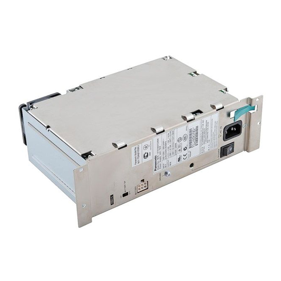
KX-TDA0103XJ / KX-TDA0104XJ / KX-TDA0108XJ / KX-TDA0103X / KX-TDA0104X / KX-TDA0108X CONTENTS Page Page 1 ABOUT LEAD FREE SOLDER (PbF: Pb free) 9 HOW TO REPLACE A FLAT PACKAGE IC 1.1. SUGGESTED PbF SOLDER 9.1. PREPARATION 1.2. HOW TO RECOGNIZE THAT Pb FREE SOLDER IS 9.2.
KX-TDA0103XJ / KX-TDA0104XJ / KX-TDA0108XJ / KX-TDA0103X / KX-TDA0104X / KX-TDA0108X 1 ABOUT LEAD FREE SOLDER (PbF: Pb free) Note: In the information below, Pb, the symbol for lead in the periodic table of elements, will refer to standard solder or solder that contains lead.
KX-TDA0103XJ / KX-TDA0104XJ / KX-TDA0108XJ / KX-TDA0103X / KX-TDA0104X / KX-TDA0108X 4.2. SYSTEM CAPACITY 4.2.1. Power Supply Unit Selection Hybrid IP-PBX needs an optional power supply unit (PSU) suitable for its configuration. Calculate the amount of "load figures" from the type and number of equipment to be connected, and determine the type of PSU that will be required.
KX-TDA0103XJ / KX-TDA0104XJ / KX-TDA0108XJ / KX-TDA0103X / KX-TDA0104X / KX-TDA0108X 5 INSTALLATION 5.1. INSTALLING/REPLACING THE POWER SUPPLY UNIT 5.1.1. Function PSU Type Lower/Upper Input Voltage Range Current Input Frequency PSU-S Lower: 100 V AC to 130 V AC 1.4 A...
Page 12
KX-TDA0103XJ / KX-TDA0104XJ / KX-TDA0108XJ / KX-TDA0103X / KX-TDA0104X / KX-TDA0108X 5.1.2. Installing the Power Supply Unit 1. Insert the PSU along the guide rails. Caution: For safety reasons, do not touch parts in the PSU. 2. Push the release lever in the direction of the arrow, so that the PSU is made to engage with the connector on the back board securely.
Page 13
KX-TDA0103XJ / KX-TDA0104XJ / KX-TDA0108XJ / KX-TDA0103X / KX-TDA0104X / KX-TDA0108X 5.1.3. Replacing the Power Supply Unit 1. Unplug the AC power cord and Back-up Battery Cable. 2. Turn the 4 screws anticlockwise to loosen them. 3. Pull the release lever in the direction of the arrow to disconnect the PSU from the back board.
KX-TDA0103XJ / KX-TDA0104XJ / KX-TDA0108XJ / KX-TDA0103X / KX-TDA0104X / KX-TDA0108X 6.2. PSU-M (KX-TDA0104XJ/X) 1. Remove the eight screws (A). 2. Remove the three screws (B). 3. Pull out the three connectors. 4. Remove the angle. 5. Separate the chassis body and chassis cover.
KX-TDA0103XJ / KX-TDA0104XJ / KX-TDA0108XJ / KX-TDA0103X / KX-TDA0104X / KX-TDA0108X 7 POWER SUPPLY UNIT CIRCUIT OPERATION The power unit supplies power to the various cards of the KX-TDA100 and KX-TDA200. The functions of the power unit are listed below.
KX-TDA0103XJ / KX-TDA0104XJ / KX-TDA0108XJ / KX-TDA0103X / KX-TDA0104X / KX-TDA0108X 7.1. PSU-S (KX-TDA0108XJ/X) This power supply unit consists of two boards. 7.1.1. Block Diagram of PSU-S...
KX-TDA0103XJ / KX-TDA0104XJ / KX-TDA0108XJ / KX-TDA0103X / KX-TDA0104X / KX-TDA0108X 7.2. CIRCUIT DESCRIPTION 7.2.1. APFC Converter This circuit corrects the input current in order to follow the sine-wave with pressurizing the rectified AC power to about 390V. 1) PFC output voltage is detected by R34-37, R41-R44, R87, R90 and R91 and is input to 1pin of IC24.
Page 21
KX-TDA0103XJ / KX-TDA0104XJ / KX-TDA0108XJ / KX-TDA0103X / KX-TDA0104X / KX-TDA0108X 7.2.2. Main Converter This circuit converts the output of APFC converter to the insulated 40V. 1) Q110 is PWM-controlled by IC121 in order to regulate the output voltage. Secondary voltage detection is performed by R250, R251and R360, and changes in the secondary voltage with respect to the collector voltage of Q247 are isolated by photocoupler PC147 sent to IC121.
Page 22
KX-TDA0103XJ / KX-TDA0104XJ / KX-TDA0108XJ / KX-TDA0103X / KX-TDA0104X / KX-TDA0108X Stepdown Converter (40V → → 30V) 7.2.3. This circuit converts the output of Main converter from 40V to 30V. 1) Q578 is PWM-controlled by IC601 in order to regulate the +30V output voltage.
Page 23
KX-TDA0103XJ / KX-TDA0104XJ / KX-TDA0108XJ / KX-TDA0103X / KX-TDA0104X / KX-TDA0108X Stepdown Converter (40V → → 15V) 7.2.4. This circuit converts the output of Main converter from 40V to 15V. 1) Q268 is PWM-controlled by IC226 in order to regulate the +15V output voltage.
Page 24
KX-TDA0103XJ / KX-TDA0104XJ / KX-TDA0108XJ / KX-TDA0103X / KX-TDA0104X / KX-TDA0108X 7.2.5. 15VPT Control Circuit This circuit controls +15VPT output voltage separated from +15V output. Q325 is the output switch controlled by IC513 in order to separate the +15VPT output voltage from +15V output.
KX-TDA0103XJ / KX-TDA0104XJ / KX-TDA0108XJ / KX-TDA0103X / KX-TDA0104X / KX-TDA0108X 7.3. PSU-M (KX-TDA0104XJ/X) This power supply unit consists of five boards. 7.3.1. Block Diagram of PSU-M...
KX-TDA0103XJ / KX-TDA0104XJ / KX-TDA0108XJ / KX-TDA0103X / KX-TDA0104X / KX-TDA0108X 7.4. CIRCUIT DESCRIPTION 7.4.1. APFC Converter This circuit corrects the input current in order to follow the sine-wave with pressurizing the rectified AC power to about 405V. 1) PFC output voltage is detected by R34, R35, R36, R49, R37, R91 and R90 and is input to 6pin of IC24.
Page 27
KX-TDA0103XJ / KX-TDA0104XJ / KX-TDA0108XJ / KX-TDA0103X / KX-TDA0104X / KX-TDA0108X 7.4.2. Main Converter This circuit converts the output of APFC converter to the insulated 40V. 1) Q110, Q111 are PWM-controlled by IC121 in order to regulate the output voltage.
Page 28
KX-TDA0103XJ / KX-TDA0104XJ / KX-TDA0108XJ / KX-TDA0103X / KX-TDA0104X / KX-TDA0108X Stepdown Converter (40V → → 30V) 7.4.3. This circuit converts the output of Main converter from 40V to 30V. 1) Q578 is PWM-controlled by IC602 in order to regulate the +30V output voltage.
Page 29
KX-TDA0103XJ / KX-TDA0104XJ / KX-TDA0108XJ / KX-TDA0103X / KX-TDA0104X / KX-TDA0108X Stepdown Converter (40V → → 15V) 7.4.4. This circuit converts the output of Main converter from 40V to 15V. 1) Q268 is PWM-controlled by IC226 in order to regulate the +15V output voltage.
Page 30
KX-TDA0103XJ / KX-TDA0104XJ / KX-TDA0108XJ / KX-TDA0103X / KX-TDA0104X / KX-TDA0108X 7.4.5. 15VPT Control Circuit This circuit controls +15VPT output voltage separated from +15V output. Q325 is the output switch controlled by IC513 in order to separate the +15VPT output voltage from +15V output.
KX-TDA0103XJ / KX-TDA0104XJ / KX-TDA0108XJ / KX-TDA0103X / KX-TDA0104X / KX-TDA0108X 7.5. PSU-L (KX-TDA0103XJ/X) This power supply unit consists of five boards. 7.5.1. Block Diagram of PSU-L...
KX-TDA0103XJ / KX-TDA0104XJ / KX-TDA0108XJ / KX-TDA0103X / KX-TDA0104X / KX-TDA0108X 7.6. CIRCUIT DESCRIPTION 7.6.1. APFC Converter This circuit corrects the input current in order to follow the sine-wave with pressurizing the rectified AC power to about 400V. 1) PFC output voltage is detected by R34~R37, R90 and R91 and is input to 6pin of IC24.
Page 33
KX-TDA0103XJ / KX-TDA0104XJ / KX-TDA0108XJ / KX-TDA0103X / KX-TDA0104X / KX-TDA0108X 7.6.2. Main Converter This circuit converts the output of APFC converter to the insulated 40V. 1) Q110 is PWM-controlled by IC121 in order to regulate the output voltage. Secondary voltage detection is performed by R250, R251and R360, and changes in the secondary voltage with respect to the collector voltage of Q247 are isolated by photocoupler PC147 sent to IC121.
Page 34
KX-TDA0103XJ / KX-TDA0104XJ / KX-TDA0108XJ / KX-TDA0103X / KX-TDA0104X / KX-TDA0108X Stepdown Converter (40V → → 30V) 7.6.3. This circuit converts the output of Main converter from 40V to 30V. 1) Q578 is PWM-controlled by IC601 in order to regulate the +30V output voltage.
Page 35
KX-TDA0103XJ / KX-TDA0104XJ / KX-TDA0108XJ / KX-TDA0103X / KX-TDA0104X / KX-TDA0108X Stepdown Converter (40V → → 15V) 7.6.4. This circuit converts the output of Main converter from 40V to 15V. 1) Q268 is PWM-controlled by IC226 in order to regulate the +15V output voltage.
Page 36
KX-TDA0103XJ / KX-TDA0104XJ / KX-TDA0108XJ / KX-TDA0103X / KX-TDA0104X / KX-TDA0108X 7.6.5. 15VPT Control Circuit This circuit controls +15VPT output voltage separated from +15V output. Q325 is the output switch controlled by IC513 in order to separate the +15VPT output voltage from +15V output.
KX-TDA0103XJ / KX-TDA0104XJ / KX-TDA0108XJ / KX-TDA0103X / KX-TDA0104X / KX-TDA0108X 8 TROUBLESHOOTING GUIDE 8.1. KX-TDA0108XJ/X POWER UNIT TROUBLE SHOOTING 8.1.1. No Voltages are Output at All 8.1.2. +41V, +30V, +15VPT are Not Output (Only +15V is Output)
Page 38
KX-TDA0103XJ / KX-TDA0104XJ / KX-TDA0108XJ / KX-TDA0103X / KX-TDA0104X / KX-TDA0108X 8.1.3. Only +41V is Not Output 8.1.4. Only +30V is Not Output 8.1.5. Only +15VPT is Not Output 8.1.6. Only +41V is Available (Other Voltage are Not Output)
Page 39
KX-TDA0103XJ / KX-TDA0104XJ / KX-TDA0108XJ / KX-TDA0103X / KX-TDA0104X / KX-TDA0108X 8.1.7. Battery Backup Function does Not Operate / PSU can Not Charge Batteries 8.1.8. AC Alarm is Sent (Although AC Power is Normal) 8.1.9. DC Alarm is Sent (Although All DC Output are Normal) 8.1.10.
Page 40
KX-TDA0103XJ / KX-TDA0104XJ / KX-TDA0108XJ / KX-TDA0103X / KX-TDA0104X / KX-TDA0108X 8.1.11. Table 2 Remark Defective mode Check point The parts which have the possibility of failure simultaneously short/open open open open short open open D132 open/short R131 D184 open...
Page 41
KX-TDA0103XJ / KX-TDA0104XJ / KX-TDA0108XJ / KX-TDA0103X / KX-TDA0104X / KX-TDA0108X Remark Defective mode Check point The parts which have the possibility of failure simultaneously short/open R165 open R168 open R169 open/short R170 short R171 short R185 short R215 open/short...
Page 42
KX-TDA0103XJ / KX-TDA0104XJ / KX-TDA0108XJ / KX-TDA0103X / KX-TDA0104X / KX-TDA0108X 8.1.13. Table 4 Remark Defective mode Check point The parts which have the possibility of failure simultaneously short/open D100 short D430 short D275 open D373 short PC145 short Q254...
Page 43
KX-TDA0103XJ / KX-TDA0104XJ / KX-TDA0108XJ / KX-TDA0103X / KX-TDA0104X / KX-TDA0108X 8.1.14. Table 5 Remark Defective mode Check point The parts which have the possibility of failure simultaneously short/open D582 open D583 short D740 open PC145 short Q574 short Q578...
Page 44
KX-TDA0103XJ / KX-TDA0104XJ / KX-TDA0108XJ / KX-TDA0103X / KX-TDA0104X / KX-TDA0108X 8.1.15. Table 6 Remark Defective mode Check point The parts which have the possibility of failure simultaneously short/open D530 open D553 open IC513 short Q325 open short Q328 short...
Page 45
KX-TDA0103XJ / KX-TDA0104XJ / KX-TDA0108XJ / KX-TDA0103X / KX-TDA0104X / KX-TDA0108X 8.1.16. Table 7 Remark Defective mode Check point The parts which have the possibility of failure simultaneously short/open D286 open D294 open D300 open short F350 F350 open Q287...
Page 46
KX-TDA0103XJ / KX-TDA0104XJ / KX-TDA0108XJ / KX-TDA0103X / KX-TDA0104X / KX-TDA0108X 8.1.17. Table 8 Remark Defective mode Check point The parts which have the possibility of failure simultaneously short/open Q404 open C/E/B short short open/short short short short R106 open...
Page 47
KX-TDA0103XJ / KX-TDA0104XJ / KX-TDA0108XJ / KX-TDA0103X / KX-TDA0104X / KX-TDA0108X 8.1.18. Table 9 Remark Defective mode Check point The parts which have the possibility of failure simultaneously short/open D271 open D407 open Q426 open C/E/B short Q720 short Q725...
Page 48
KX-TDA0103XJ / KX-TDA0104XJ / KX-TDA0108XJ / KX-TDA0103X / KX-TDA0104X / KX-TDA0108X 8.1.19. Table 10 Remark Defective mode Check point The parts which have the possibility of failure simultaneously short/open D260 open IC601 D281 open D373 short PC429 open/short 1/2/3/4 Q255...
KX-TDA0103XJ / KX-TDA0104XJ / KX-TDA0108XJ / KX-TDA0103X / KX-TDA0104X / KX-TDA0108X 8.2. KX-TDA0104XJ/X POWER UNIT TROUBLE SHOOTING 8.2.1. No Voltages are Output at All 8.2.2. +41V, +30V, +15VPT are Not Output (Only +15V is Output)
Page 50
KX-TDA0103XJ / KX-TDA0104XJ / KX-TDA0108XJ / KX-TDA0103X / KX-TDA0104X / KX-TDA0108X 8.2.3. Only +41V is Not Output 8.2.4. Only +30V is Not Output 8.2.5. Only +15VPT is Not Output 8.2.6. Only +41V is Available (Other Voltage are Not Output) 8.2.7.
Page 51
KX-TDA0103XJ / KX-TDA0104XJ / KX-TDA0108XJ / KX-TDA0103X / KX-TDA0104X / KX-TDA0108X 8.2.8. AC Alarm is Sent (Although AC Power is Normal) 8.2.9. DC Alarm is Sent (Although All DC Output are Normal) 8.2.10. Table 1 Remark Defective mode Check point...
Page 52
KX-TDA0103XJ / KX-TDA0104XJ / KX-TDA0108XJ / KX-TDA0103X / KX-TDA0104X / KX-TDA0108X 8.2.11. Table 2 Remark Defective mode Check point The parts which have the possibility of failure simultaneously short/open open short short short open open IC24 IC121 open open open...
Page 53
KX-TDA0103XJ / KX-TDA0104XJ / KX-TDA0108XJ / KX-TDA0103X / KX-TDA0104X / KX-TDA0108X Remark Defective mode Check point The parts which have the possibility of failure simultaneously short/open open Q577 open Q578 short Q591 short Q600 open Q660 short Q661 short 8.2.12. Table 3...
Page 54
KX-TDA0103XJ / KX-TDA0104XJ / KX-TDA0108XJ / KX-TDA0103X / KX-TDA0104X / KX-TDA0108X 8.2.13. Table 4 Remark Defective mode Check point The parts which have the possibility of failure simultaneously short/open D326 open D346 short Q319 short Q320 open short Q379 open...
Page 55
KX-TDA0103XJ / KX-TDA0104XJ / KX-TDA0108XJ / KX-TDA0103X / KX-TDA0104X / KX-TDA0108X 8.2.14. Table 5 Remark Defective mode Check point The parts which have the possibility of failure simultaneously short/open D582 open D583 short Q578 open D615 open Q574 short Q577...
Page 56
KX-TDA0103XJ / KX-TDA0104XJ / KX-TDA0108XJ / KX-TDA0103X / KX-TDA0104X / KX-TDA0108X 8.2.15. Table 6 Remark Defective mode Check point The parts which have the possibility of failure simultaneously short/open D668 open IC513 short Q325 open short Q466 short Q526 short...
Page 57
KX-TDA0103XJ / KX-TDA0104XJ / KX-TDA0108XJ / KX-TDA0103X / KX-TDA0104X / KX-TDA0108X 8.2.16. Table 7 Remark Defective mode Check point The parts which have the possibility of failure simultaneously short/open D220 short D281 open PC429 open short Q218 short Q222 open...
Page 58
KX-TDA0103XJ / KX-TDA0104XJ / KX-TDA0108XJ / KX-TDA0103X / KX-TDA0104X / KX-TDA0108X 8.2.17. Table 8 Remark Defective mode Check point The parts which have the possibility of failure simultaneously short/open D238 open D286 open D300 open short F350 D301 short D390...
Page 59
KX-TDA0103XJ / KX-TDA0104XJ / KX-TDA0108XJ / KX-TDA0103X / KX-TDA0104X / KX-TDA0108X 8.2.18. Table 9 Remark Defective mode Check point The parts which have the possibility of failure simultaneously short/open D184 open D535 open PC429 short open Q163 open short Q167...
Page 60
KX-TDA0103XJ / KX-TDA0104XJ / KX-TDA0108XJ / KX-TDA0103X / KX-TDA0104X / KX-TDA0108X 8.2.19. Table 10 Remark Defective mode Check point The parts which have the possibility of failure simultaneously short/open D361 open short R368 D407 open Q325 short Q426 open short...
KX-TDA0103XJ / KX-TDA0104XJ / KX-TDA0108XJ / KX-TDA0103X / KX-TDA0104X / KX-TDA0108X 8.3. KX-TDA0103XJ/X POWER UNIT TROUBLE SHOOTING 8.3.1. No Voltages are Output at All 8.3.2. +41V, +30V, +15VPT are Not Output (Only +15V is Output)
Page 62
KX-TDA0103XJ / KX-TDA0104XJ / KX-TDA0108XJ / KX-TDA0103X / KX-TDA0104X / KX-TDA0108X 8.3.3. Only +41V is Not Output 8.3.4. Only +30V is Not Output 8.3.5. Only +15VPT is Not Output 8.3.6. Only +41V is Available (Other Voltage are Not Output) 8.3.7.
Page 63
KX-TDA0103XJ / KX-TDA0104XJ / KX-TDA0108XJ / KX-TDA0103X / KX-TDA0104X / KX-TDA0108X 8.3.8. AC Alarm is Sent (Although AC Power is Normal) 8.3.9. DC Alarm is Sent (Although All DC Output are Normal) 8.3.10. Cooling Fan Trouble 1) Rotation sound is unusual.
Page 64
KX-TDA0103XJ / KX-TDA0104XJ / KX-TDA0108XJ / KX-TDA0103X / KX-TDA0104X / KX-TDA0108X 8.3.11. Table 1 Remark Defective mode Check point The parts which have the possibility of failure simultaneously short/open short + - ~ - - ~ + - - short...
Page 65
KX-TDA0103XJ / KX-TDA0104XJ / KX-TDA0108XJ / KX-TDA0103X / KX-TDA0104X / KX-TDA0108X Remark Defective mode Check point The parts which have the possibility of failure simultaneously short/open open short IC24 IC121 open short open short Q110 short Q110 Q111 Q150 Q151...
Page 66
KX-TDA0103XJ / KX-TDA0104XJ / KX-TDA0108XJ / KX-TDA0103X / KX-TDA0104X / KX-TDA0108X 8.3.13. Table 3 Remark Defective mode Check point The parts which have the possibility of failure short/open simultaneously D184 open D533 open D535 open Q163 open Q163 short Q167...
Page 67
KX-TDA0103XJ / KX-TDA0104XJ / KX-TDA0108XJ / KX-TDA0103X / KX-TDA0104X / KX-TDA0108X 8.3.14. Table 4 Remark Defective mode Check point The parts which have the possibility of failure simultaneously short/open D326 open D346 short Q319 short Q320 open Q320 short Q379...
Page 68
KX-TDA0103XJ / KX-TDA0104XJ / KX-TDA0108XJ / KX-TDA0103X / KX-TDA0104X / KX-TDA0108X 8.3.15. Table 5 Remark Defective mode Check point The parts which have the possibility of failure simultaneously short/open D582 open D583 short Q578 D583 open Q574 short Q577 short...
Page 69
KX-TDA0103XJ / KX-TDA0104XJ / KX-TDA0108XJ / KX-TDA0103X / KX-TDA0104X / KX-TDA0108X 8.3.16. Table 6 Remark Defective mode Check point The parts which have the possibility of failure simultaneously short/open D668 open IC513 D668 short R667 Q325 open Q325 short Q466...
Page 70
KX-TDA0103XJ / KX-TDA0104XJ / KX-TDA0108XJ / KX-TDA0103X / KX-TDA0104X / KX-TDA0108X 8.3.17. Table 7 Remark Defective mode Check point The parts which have the possibility of failure simultaneously short/open D222 short short open/short short short short R106 open R110 short...
Page 71
KX-TDA0103XJ / KX-TDA0104XJ / KX-TDA0108XJ / KX-TDA0103X / KX-TDA0104X / KX-TDA0108X 8.3.18. Table 8 Remark Defective mode Check point The parts which have the possibility of failure simultaneously short/open D238 open D286 open D300 open D300 short F350 D301 short...
Page 72
KX-TDA0103XJ / KX-TDA0104XJ / KX-TDA0108XJ / KX-TDA0103X / KX-TDA0104X / KX-TDA0108X 8.3.19. Table 9 Remark Defective mode Check point The parts which have the possibility of failure simultaneously short/open D184 open D535 open PC429 short PC429 open Q163 open Q163...
Page 73
KX-TDA0103XJ / KX-TDA0104XJ / KX-TDA0108XJ / KX-TDA0103X / KX-TDA0104X / KX-TDA0108X 8.3.20. Table 10 Remark Defective mode Check point The parts which have the possibility of failure simultaneously short/open D361 open D361 short R368 D407 open Q506 short Q426 open...
KX-TDA0103XJ / KX-TDA0104XJ / KX-TDA0108XJ / KX-TDA0103X / KX-TDA0104X / KX-TDA0108X 9 HOW TO REPLACE A FLAT PACKAGE IC 9.1. PREPARATION 9.3. REMOVING SOLDER FROM BETWEEN PINS · PbF (: Pb free) Solder · Soldering Iron 1. Add a small amount of solder to the bridged pins.
KX-TDA0103XJ / KX-TDA0104XJ / KX-TDA0108XJ / KX-TDA0103X / KX-TDA0104X / KX-TDA0108X 12 REPLACEMENT PARTS LIST Note: Ref. Part No. Part Name & Description Remarks 1. RTL (Retention Time Limited) XYN3+F6 SCREW The marking (RTL) indicates that the Retention Time is...
Page 83
KX-TDA0103XJ / KX-TDA0104XJ / KX-TDA0108XJ / KX-TDA0103X / KX-TDA0104X / KX-TDA0108X Ref. Part No. Part Name & Description Remarks Ref. Part No. Part Name & Description Remarks D295 PSVD1GU42 DIODE(SI) C603 PSCEA50VB2R2 D300 PSVDFCH10A10 DIODE(SI) C604 PSCKD1H104Z D306 PSVDRD9R1ESA DIODE(SI)
Page 84
KX-TDA0103XJ / KX-TDA0104XJ / KX-TDA0108XJ / KX-TDA0103X / KX-TDA0104X / KX-TDA0108X Ref. Part No. Part Name & Description Remarks Ref. Part No. Part Name & Description Remarks R264 ERX2SJR10 L192 EXCELDR35 COMPONENTS PART R266 ERDS2TJ471 L195 EXCELDR35 COMPONENTS PART R267...
Page 85
KX-TDA0103XJ / KX-TDA0104XJ / KX-TDA0108XJ / KX-TDA0103X / KX-TDA0104X / KX-TDA0108X Ref. Part No. Part Name & Description Remarks Ref. Part No. Part Name & Description Remarks 1SS131 DIODE(SI) C463 PSCKD1H104Z D140 1SS131 DIODE(SI) C470 PSQE50F2D103 0.01 D154 1SS131 DIODE(SI)
KX-TDA0103XJ / KX-TDA0104XJ / KX-TDA0108XJ / KX-TDA0103X / KX-TDA0104X / KX-TDA0108X 13 FOR THE SCHEMATIC DIAGRAM Note: 1. DC voltage measurements are taken with an oscilloscope or a tester with a ground. 2. The schematic diagrams and circuit board may be modified at any time with the development of new technology.
Page 126
D460 BROWN CAUTION: FAR CONTINUED PROTECTION AGAINST RISK OF FIRE, REPLACE ONLY WITH SAME TYPE AND RATINGS OF FUSE. BLUE JP153 C306 C305 C304 RED BATT+ BLUE BATT- R561 R459 R289 D560 R293 R291 Q292 JP164 R296 R290 JP163 C290 BLUE BROWN C366...
Page 131
REPLACE ONLY WITH SAME TYPE AND RATINGS OF FUSE. BLUE JP172 C305 C306 C304 BLUE BATT+ BATT- D286 R561 JP153 R459 R289 D560 R293 R291 Q292 JP165 JP164 R296 JP163 R290 C290 C366 BLUE BROWN D699 R696 KX-TDA0103XJ/KX-TDA0103X L-TYPE POWER SUPPLY UNIT (PSU-L) 2/6...