Panasonic MADDT1207 Technical Reference

Panasonic MADDT1207 Technical Reference

Minas a4 series ac servo motor & driver
Hide thumbs Also See for MADDT1207:

Advertisement

If you are the first user of this product, please be sure to purchase and read
the optional Engineering Material (DV0P4210), or downloaded Instruction
Manual from our Web Site.
[Web address of Motor Company, Matsushita Electric Industrial Co., Ltd.]
http://industrial.panasonic.com/ww/i_e/25000/motor_fa_e/motor_fa_e.html
<Contents>
1. Introduction ................................. B2
On Opening the Package ............................... B2
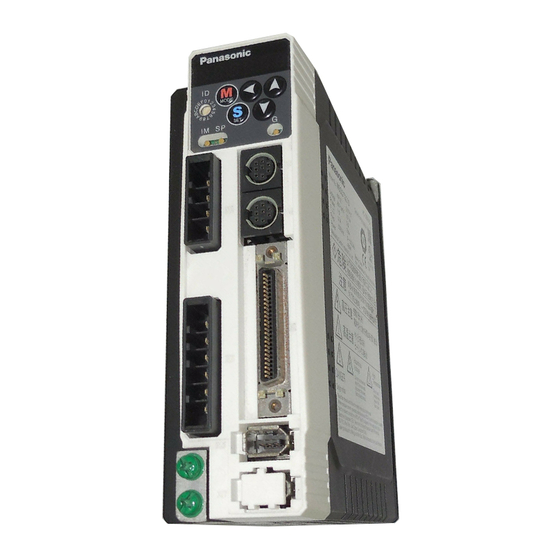
Check of the Driver Model .............................. B2
Check of the Motor Model .............................. B3
2. Installation .................................. B4
Driver .............................................................. B4
Motor .............................................................. B6
Console .......................................................... B8
Technical reference
AC Servo Motor & Driver
Thank you very much for your
purchase of Panasonic AC Servo
Motor & Driver, MINAS A4-series.
Before use, refer this technical
reference and safety instructions
to ensure proper use. Keep this
technical reference and read
when necessary.
Make sure to forward this technical
reference for safety to the final
user.
page
4. Parameter .................................. B27
Outline of Parameter .................................... B27
How to Set .................................................... B27
Setup with the Front Panel ........................... B27
Setup with the Console ................................ B28
How to Connect ............................................ B29
5. Protective Functions ................ B36
Conformity to UL Standards ......................... B44
8. Built-in Holding Brake ............. B45
9. Dynamic Brake ......................... B47
MINAS A4-series
®
.......................................................
page
B28
IMC54D
Z0404-6066

Advertisement

Table of Contents
loading

Summary of Contents for Panasonic MADDT1207

  • Page 1: Table Of Contents

    Technical reference AC Servo Motor & Driver MINAS A4-series • Thank you very much for your purchase of Panasonic AC Servo Motor & Driver, MINAS A4-series. • Before use, refer this technical reference and safety instructions to ensure proper use. Keep this technical reference and read when necessary.
  • Page 2: Introduction

    1. Introduction On Opening the Product Package • Make sure that the model is what you have ordered. • Check if the product is damaged or not during transportation. • Check if the instruction manual is attached or not. • Check if the power connector and motor connecters (CN X1 and CN X2 connectors) are attached or not (A to D-frame).
  • Page 3: Check Of The Motor Model

    Check of the Motor Model Contents of Name Plate Serial Number Model CONT. TORQUE 0.64 Nm 04 11 0001 e.g.) : AC SERVO MOTOR RATING MSMD5AZS1S MODEL No. INS. CLASS B (TÜV) A (UL) Rated input voltage/current Lot number INPUT 3ØAC IP65 CONNECTION RATED OUTPUT...
  • Page 4: Installation

    2. Installation Install the driver and the motor properly to avoid a breakdown or an accident. Driver Installation Place 1) Indoors, where the products are not subjected to rain or direct sun beams. The prod- ucts are not waterproof. 2) Where the products are not subjected to corrosive atmospheres such as hydrogen sulfide, sulfurous acid, chlorine, ammonia, chloric gas, sulfuric gas, acid, alkaline and salt and so on, and are free from splash of inflammable gas, grinding oil, oil mist, iron powder or chips and etc.
  • Page 5 E and F-frame Mounting bracket Mounting Direction and Spacing • Reserve enough surround- ing space for effective cool- 100mm ing. or more • Install fans to provide uni- form distribution of tem- perature in the control 10mm 10mm 10mm panel. 40mm 40mm more...
  • Page 6: Motor

    2. Installation Motor Installation Place Since the conditions of location affect a lot to the motor life, select a place which meets the conditions below. 1) Indoors, where the products are not subjected to rain or direct sun beam. The prod- ucts are not waterproof.
  • Page 7 Oil/Water Protection 1) Don't submerge the motor cable to water or oil. Motor Cable 2) Install the motor with the cable outlet facing downward. 3) Avoid a place where the motor is subjected to oil or water. 4) Use the motor with an oil seal when used with the gear re- ducer, so that the oil may not enter to the motor through shaft.
  • Page 8: Console

    2. Installation Console Installation Place 1) Indoors, where the products are not subjected to rain or direct sun beam. The prod- ucts are not waterproof. 2) Where the products are not subjected to corrosive atmospheres such as hydrogen sulfide, sulfurous acid, chlorine, ammonia, chloric gas, sulfuric gas, acid, alkaline and salt and so on, and are free from splash of inflammable gas, grinding oil, oil mist, iron powder or chips and etc.
  • Page 9 How to Connect Connect to CN X4. <Remarks> • Connect the console connector securely to CN X4 connector of the driver. • Never pull the cable to plug in or plug out. – B9 –...
  • Page 10: System Configuration And Wiring

    3. System Configuration and Wiring Overall Wiring (Connecting Example of C-frame, 3-phase) • Wiring of the Main Circuit Circuit Breaker (NFB) Use the circuit breaker matching capacity of the power source to protect the power lines. Noise Filter (NF) Prevents external noise from the pow- er lines.
  • Page 11 PC (to be supplied by customer) Setup support software "PANATERM " ® DV0P4460 Console (option) DV0P4420 • Wiring to Connector, CN X3/X4 (option) (Connection to PC or host controller) • Wiring to Connector, CN X5 (Connection to host controller) Junction cable for encoder •...
  • Page 12: Overall Wiring (Connecting Example Of E-Frame)

    3. System Configuration and Wiring Overall Wiring (Connecting Example of E-frame) • Wiring of the Main Circuit Circuit Breaker (NFB) Use the circuit breaker matching capacity of the power source to protect the power lines. Noise Filter (NF) Prevents external noise from the pow- er lines.
  • Page 13 PC (to be supplied by customer) Setup support software "PANATERM " ® DV0P4460 Console (option) DV0P4420 • Wiring to Connector, CN X3/X4 (option) (Connection to PC or host controller) • Wiring to Connector, CN X5 (Connection to host controller) • Wiring to Connector, CN X6 (Connection to encoder) Junction cable for encoder...
  • Page 14: Driver And List Of Applicable Peripheral Equipments

    3. System Configuration and Wiring Driver and List of Applicable Peripheral Equipments Noise Cable Cable Required Circuit Applicable Rated Noise Surge Magnetic Power breaker Driver Voltage Connection filter for diameter diameter (at the rated (rated motor output filter absorber contactor signal (main circuit) (control circuit)
  • Page 15 Required Noise Cable Cable Circuit Applicable Rated Noise Surge Magnetic Power breaker Driver Voltage Connection filter for diameter diameter (at the rated (rated motor output filter absorber contactor signal (main circuit) (control circuit) load) current) approx. MGMA 2.0kW 3.8kVA MDMA BMF6352N MHMA approx.
  • Page 16: Wiring Of The Main Circuit (A To D-Frame)

    3. System Configuration and Wiring Wiring of the Main Circuit (A to D-frame) • Wiring should be performed by a specialist or an authorized personnel. • Do not turn on the power until the wiring is completed. Tips on Wiring 8~9mm 1) Peel off the insulation cover of the cable.
  • Page 17: Wiring Of The Main Circuit (E And F-Frame)

    Wiring of the Main Circuit (E and F-frame) • Wiring should be performed by a specialist or an authorized personnel. • Do not turn on the power until the wiring is completed. Tips on Wiring 1) Take off the cover fixing screws, and detach the terminal cover. 2) Make wiring Use clamp type terminals of round shape with insulation cover for wiring to the termi- nal block.
  • Page 18: Wiring Method To Connector (A To D-Frame)

    3. System Configuration and Wiring Wiring method to connector (A to D-frame) • Follow the procedures below for the wiring connection to the Connector CN X1 and X2 . How to connect 8 to 9mm 1. Peel off the insulation cover of the cable. (see the right fig for exact length for peeling.) 2.
  • Page 19 Wiring Diagram Compose the circuit so that the main circuit power will be shut off when an error occurs. In Case of Single Phase, 100V (A and B-frame) +10% +10% Power supply Single phase, 100V to 115V –15% –15% Built-in thermostat of an external regenerative resistor (light yellow) ON OFF Surge absorber...
  • Page 20 3. System Configuration and Wiring In Case of Single Phase, 200V (C and D-frame) * When you use motor model of MSMA, MDMA, MFMA, MHMA +10% +10% Power supply Single phase, 200V to 240V –15% –15% and MGMA, use the connections <Remarks>...
  • Page 21 In Case of 3-Phase, 200V (E and F-frame) [Motor portion] Connector : by Japan Aviation Electronics Ind. +10% +10% Power supply 3-phase, 200V to 230V –15% –15% Built-in thermostat of an external regenerative resistor (light yellow) ON OFF JL04V-2E20-4PE-B-R Surge absorber JL04HV-2E22-22PE-B-R PIN No.
  • Page 22: Wiring To The Connector, Cn X6 (Connection To Encoder)

    3. System Configuration and Wiring Wiring to the Connector, CN X6 (Connection to Encoder) Wiring Diagram In case of 2500P/r incremental encoder MSMD 50W to 750W MAMA 100W to 750W MQMA 100W to 400W CN X6 White Black Regulator Light Blue Purple Case Twisted pair...
  • Page 23 Wiring Diagram In case of 17-bit absolute/incremental encoder MSMD 50W to 750W MAMA 100W to 750W MQMA 100W to 400W CN X6 White Black Regulator battery BAT+ Pink BAT– Light Blue Purple Yellow/Green Case Twisted pair 172169-1 172161-1 (by Tyco Electronics, AMP) (by Tyco Electronics, AMP) motor Junction cable...
  • Page 24: Wiring For Typical Control Modes To The Connector Cn X5

    3. System Configuration and Wiring Wiring for Typical Control Modes to the Connector CN X5 Wiring Example of Position Control Mode – B24 –...
  • Page 25 Wiring Example of Velocity Control Mode – B25 –...
  • Page 26 3. System Configuration and Wiring Wiring Example of Torque Control Mode – B26 –...
  • Page 27: Parameter

    4. Parameter Outline of Parameter This driver is equipped with various parameters to set up its characteristics and func- tions. This section describes the function and purpose of each parameter. Read and comprehend very well so that you can adjust this diver in optimum condition for your running requirements.
  • Page 28: Outline Of Panaterm

    4. Parameter Outline of PANATERM ® With the PANATERM , you can execute the followings. ® 1) Setup and storage of parameters, and writing to the memory (EEPROM). 2) Monitoring of I/O and pulse input and load factor. 3) Display of the present alarm and reference of the error history. 4) Data measurement of the wave-form graphic and bringing of the stored data.
  • Page 29: How To Connect

    How to Connect RS232 connection cable (option) DV0P1960 (for DOS/V machines) Connect to CN X4 Setup disc of setup support software, PANATERM ® • DV0P4460 : English/Japanese version (option) Connect to CN X4 Console DV0P4420 (option) <Remarks> • Connect the console connector to the connector, CN X4 of the driver securely. •...
  • Page 30: Composition And List Of Parameters

    4. Parameter Composition and List of Parameters Parameter No. Group Outline Functional selection 00 to 0F You can select a control mode, designate I/O signals and set up a baud rate. Adjustment 10 to 1F, You can set up servo gains (1st and 2nd) of 27 to 2E position, velocity, integration, etc, and time constants of various filters.
  • Page 31 Parameters for Functional Selection Parameter Related control Set up of parameter Range Default Unit mode Address of axis 0 to 15 – Initial display of LED – 0 to 17 Setup of control mode 0 to 6 – Selection of torque limit 0 to 3 –...
  • Page 32 4. Parameter Parameters for Adjustment of Time Constant for Gains and Filters Parameter Default Related control Set up of parameter Range Unit A to D to mode C-frame F-frame 2nd gain of position loop 0 to 3000 <73> <38> P, F 2nd gain of velocity loop 1 to 3500 <35>...
  • Page 33 Parameters for Adjustment (2nd Gain Switching Function) Parameter Related control Set up of parameter Range Default Unit mode Setup of 2nd gain 0 to 1 <1> – 1st mode of control switching 0 to 10 <0> – 1st delay time of control switching 0 to 10000 <30>...
  • Page 34 4. Parameter Parameter Related control Set up of parameter Range Default Unit mode 1st numerator of electronic gear 0 to 10000 – P, F 2nd numerator of electronic gear 0 to 10000 – P, F Multiplier for numerator of electronic gear 0 to 17 –...
  • Page 35 Parameters for Sequence Parameter Related control Set up of parameter Range Default Unit mode In-position (positioning complete) range 0 to 32767 Pulse P, F Zero speed 10 to 20000 r/min At-speed (arrived speed) 10 to 20000 1000 r/min S, T Setup of in-position output 0 to 3 –...
  • Page 36: Protective Functions

    5. Protective Functions Protective Function (What Is Error Code ?) • Various protective functions are equipped in the driver. When these are triggered, the motor will stall due to error, the driver will turn the Servo-Alarm output (ALM) to off (open).
  • Page 37 Error Error code Protective function code Protective function Control power supply under- voltage Analog input excess protection protection Absolute system down error Over-voltage protection protection Main power supply under-voltage Absolute counter over error protection protection Over-current protection Absolute over-speed error protection Absolute single turn counter error Over-heat protection protection...
  • Page 38: Maintenance And Inspections . B38

    6. Maintenance and Inspections • Routine maintenance and inspection of the driver and motor are essential for the proper and safe operation. Notes on Maintenance and Inspection 1) Turn on and turn off should be done by operators or inspectors themselves. 2) Internal circuit of the driver is kept charged with high voltage for a while even after power-off.
  • Page 39 Guideline for Parts Replacement Use the table below for a reference. Parts replacement cycle varies depending on the actual operating conditions. Defective parts should be replaced or repaired when any error have occurred. Disassembling for inspection and repair should be carried out only by authorized dealers or ser- vice company.
  • Page 40: Conformity To Ec Directives And Ul Standards

    7. Conformity to EC Directives and UL Standards EC Directives The EC Directives apply to all such electronic products as those having specific func- tions and have been exported to EU and directly sold to general consumers. Those products are required to conform to the EU unified standards and to furnish the CE marking on the products.
  • Page 41: Composition Of Peripheral Equipments

    Composition of Peripheral Equipments Installation Environment Use the servo driver in the environment of Pollution Degree 1 or 2 prescribed in IEC- 60664-1 (e.g. Install the driver in control panel with IP54 protection structure.) Control box Controller Insulated power supply for interface CN X5 Driver...
  • Page 42 7. Conformity to EC Directives and UL Standards Noise Filter When you install one noise filter at the power supply for multi-axes application, contact to a manufacture of the noise filter. Voltage specifications Option part No. Manufacturer’s part No. Applicable driver (frame) Manufacturer for driver DV0P4170...
  • Page 43 Surge Absorber Provide a surge absorber for the primary side of noise filter. <Remarks> Take off the surge absorber when you execute a dielectric test to the machine or equip- ment, or it may damage the surge absorber. Voltage specifications Option part No.
  • Page 44: Conformity To Ul Standards

    7. Conformity to EC Directives and UL Standards Noise Filter for Signal Lines * Install noise filters for signal lines to all cables (power cable, motor cable, encoder cable and interface cable) 39±1 * In case of D-frame, install 3 noise 34±1 Mass: 62.8g filters at power line.
  • Page 45: Built-In Holding Brake

    8. Built-in Holding Brake In the applications where the motor drives the vertical axis, this brake would be used to hold and prevent the work (moving load) from falling by gravity while the power to the servo is shut off. Use this built-in brake for "Holding"...
  • Page 46 8. Built-in Holding Brake Rotor Exciting Static Engaging Releasing Permissible Permissible Motor Motor Releasing inertia current friction time time work (J) per total work x 10 DC A torque –4 series output voltage one braking x 10 (at cool-off) • •...
  • Page 47: Dynamic Brake

    9. Dynamic Brake This driver is equipped with a dynamic brake for emergency stop. Pay a special attention to the followings. <Caution> 1.Dynamic brake is only for emergency stop. Do not start/stop the motor by turning on/off the Servo-ON signal (SRV-ON). Or it may damage the dynamic brake circuit of the driver.
  • Page 48: Check Of The Combination Of The Driver And The Motor

    <Remarks> Do not use in other combinations than those listed below. Applicable motor Applicable driver Power Motor Rated Rated supply Model Model Frame series rotational speed output Single phase, MAMA012P1* 100W MADDT1207 A-frame MAMA 200V MAMA022P1* 200W MBDDT2210 B-frame Ultra low 5000r/min 3-phase, MAMA042P1* 400W MCDDT3520 C-frame inertia 200V...
  • Page 49 <Remarks> Do not use in other combinations than those listed below. Applicable motor Applicable driver Power Motor Rated Rated supply Model Model Frame series rotational speed output Single phase, MAMA012S1* 100W MADDT1207 A-frame MAMA 200V MAMA022S1* 200W MBDDT2210 B-frame Ultra low 5000r/min 3-phase, MAMA042S1* 400W MCDDT3520 C-frame inertia 200V...
  • Page 50 10. Check of the Combination of the Driver and the Motor Applicable motor Applicable driver Power Motor Rated Rated supply Model Model Frame series rotational speed output Single/3-phase, MDMA102S1* 1.0kW MDDDT3530 D-frame 200V MDMA152S1* 1.5kW MDDDT5540 MDMA MDMA202S1* 2.0kW MEDDT7364 E-frame Middle 2000r/min...
  • Page 51: After-Sale Service (Repair)

    After-Sale Service (Repair) Repair Consult to a dealer from whom you have purchased the product for details of repair. When the product is incorporated to the machine or equipment you have purchased, consult to the manufacture or the dealer of the machine or equipment. Cautions for Proper Use •...
  • Page 52 Technical information Technical information of this product (Instruction Manual, CAD data) can be downloaded from the following web site. http://industrial.panasonic.com/ww/i_e/25000/motor_fa_e/motor_fa_e.html MEMO (Fill in the blanks for reference in case of inquiry or repair.) Date of Model No. purchase GHV Vertriebs-GmbH...

Table of Contents