Table of Contents
Advertisement
If you are the first user of this product, please be sure to purchase and read
the optional Engineering Material (DV0P4210), or downloaded Instruction
Manual from our Web Site.
[Web address of Motor Company, Matsushita Electric Industrial Co., Ltd.]
http://industrial.panasonic.com/ww/i_e/25000/motor_fa_e/motor_fa_e.html
<Contents>
1. Introduction ................................. B2
On Opening the Package ............................... B2
Check of the Driver Model .............................. B2
Check of the Motor Model .............................. B3
2. Installation .................................. B4
Driver .............................................................. B4
Motor .............................................................. B6
Console .......................................................... B8
Technical reference
AC Servo Motor & Driver
•
Thank you very much for your
purchase of Panasonic AC Servo
Motor & Driver, MINAS A4-series.
•
Before use, refer this technical
reference and safety instructions
to ensure proper use. Keep this
technical reference and read
when necessary.
•
Make sure to forward this technical
reference for safety to the final
user.
page
4. Parameter .................................. B27
Outline of Parameter .................................... B27
How to Set .................................................... B27
Setup with the Front Panel ........................... B27
Setup with the Console ................................ B28
How to Connect ............................................ B29
Composition and List of Parameters ............ B30
5. Protective Functions ................ B36
Composition of Peripheral Equipments ........ B41
Conformity to UL Standards ......................... B44
8. Built-in Holding Brake ............. B45
9. Dynamic Brake ......................... B47
After-Sale Service (Repair) .......... B51
MINAS A4-series
®
.......................................................
page
B28
IMC54D
Z0404-6066
Advertisement
Table of Contents

Related Manuals for Panasonic MCDDT3520


Summarization of Contents
1. Introduction
On Opening the Product Package
Check package contents, damage, and manual for the AC Servo Motor & Driver.
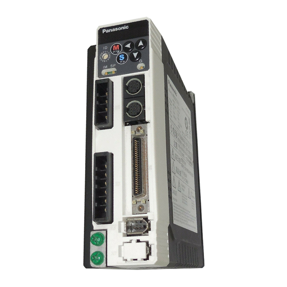
Check of the Driver Model
How to identify the AC Servo Driver model by checking its nameplate and model designation.
Check of the Motor Model
Guide to verifying the AC Servo Motor model using its nameplate and model designation.
2. Installation
Driver
Instructions for installing the AC Servo Driver, including suitable locations and environmental conditions.
Installation Place
Specifies recommended locations for installing the driver, avoiding water, dust, and corrosive atmospheres.
Environmental Conditions
Lists acceptable ambient temperature, humidity, vibration, and altitude for driver operation.
How to Install
Details the rack-mount and base-mount installation procedures for the AC Servo Driver.
Mounting Direction and Spacing
Guidelines for driver mounting orientation and spacing to ensure proper cooling and ventilation.
Motor
Installation guidelines for the AC Servo Motor, including suitable locations and environmental conditions.
Installation Place
Specifies recommended locations for installing the motor, avoiding water, dust, and heat sources.
Environmental Conditions
Lists acceptable ambient temperature, humidity, vibration, and enclosure ratings for motor operation.
How to Install
Explains horizontal and vertical mounting options for the AC Servo Motor.
Oil/Water Protection
Precautions to protect the motor from oil, water, and proper cable installation.
Stress to Cables
Guidelines for managing cable stress and bending radius to prevent damage.
Permissible Load to Output Shaft
Information on radial and thrust loads allowed on the motor shaft during operation.
Notes on Installation
Important installation precautions, including avoiding shaft impact and ensuring alignment.
Console
Installation requirements for the console, including location and environmental conditions.
Installation Place
Specifies suitable locations for the console, avoiding water, dust, and corrosive atmospheres.
Environmental Conditions
Lists acceptable ambient temperature, humidity, vibration, and impact resistance for the console.
How to Connect
Steps for connecting the console to the driver using connector CN X4.
3. System Configuration and Wiring
Overall Wiring (Connecting Example of C-frame, 3-phase)
Diagram and explanation of main circuit wiring for C-frame, 3-phase systems.
Wiring Diagram
Visual representation of the system configuration and wiring for various components.
Overall Wiring (Connecting Example of E-frame)
Diagram and explanation of main circuit wiring for E-frame systems.
Driver and List of Applicable Peripheral Equipments
Table detailing drivers, applicable motors, and necessary peripheral equipment.
Wiring of the Main Circuit (A to D-frame)
Detailed wiring instructions for the main circuit of A to D-frame drivers.
Tips on Wiring
Practical advice for performing main circuit wiring for A to D-frame drivers.
Wiring of the Main Circuit (E and F-frame)
Detailed wiring instructions for the main circuit of E and F-frame drivers.
Tips on Wiring
Practical advice for performing main circuit wiring for E and F-frame drivers.
Wiring method to connector (A to D-frame)
Step-by-step guide for wiring to connectors CN X1 and X2 for A to D-frame.
Wiring Diagram
Wiring diagrams for single-phase 100V and 200V (A and B-frame) systems.
Wiring Diagram
Wiring diagrams for single-phase 200V (C and D-frame) and 3-phase 200V (C and D-frame) systems.
Wiring Diagram
Wiring diagrams for 3-phase 200V (E and F-frame) systems.
Wiring to the Connector, CN X6 (Connection to Encoder)
Wiring diagram for connecting the encoder (2500P/r incremental) to connector CN X6.
Wiring to the Connector, CN X6 (Connection to Encoder)
Wiring diagram for connecting the encoder (17-bit absolute/incremental) to connector CN X6.
Wiring for Typical Control Modes to the Connector CN X5
Wiring examples for Position Control Mode to connector CN X5.
Wiring Example of Velocity Control Mode
Wiring example for Velocity Control Mode to connector CN X5.
Wiring Example of Torque Control Mode
Wiring example for Torque Control Mode to connector CN X5.
4. Parameter
Outline of Parameter
Overview of the driver's parameters for setting characteristics and functions.
How to Set
Methods for setting parameters using the front panel, software, or console.
Setup with the Front Panel
Guide to operating the driver's front panel for parameter setup and mode selection.
Outline of PANATERM®
Capabilities of the PANATERM® setup support software for parameter management.
Setup with the Console
Guide to operating the console for parameter setup and mode selection.
How to Connect
Instructions for connecting the PC setup software or console to the driver.
Composition and List of Parameters
Categorization and listing of parameters by function group and control mode.
Parameters for Functional Selection
Details on parameters for selecting control modes, I/O signals, and baud rates.
Parameters for Adjustment of Time Constant for Gains and Filters
Parameters related to adjusting time constants for servo gains and filters.
Parameters for Adjustment of Time Constant for Gains and Filters
Continues parameters for adjusting time constants for servo gains and filters.
Parameters for Auto-Gain Tuning
Parameters related to auto-gain tuning, inertia ratio, and adaptive filters.
Parameters for Adjustment (2nd Gain Switching Function)
Parameters for configuring the second gain switching function for servo control.
Parameters for Position Control
Parameters specific to position control, including pulse input and output settings.
Parameters for Position Control
Continues parameters for position control, including electronic gear settings.
Parameters for Velocity/Torque control
Parameters for setting speed commands, acceleration/deceleration, and torque limits.
Parameters for Sequence
Parameters for controlling sequence actions like positioning, speed, and brake engagement.
Parameters for Full-Closed Control
Parameters for full-closed loop control, related to external scales.
5. Protective Functions
Protective Function (What Is Error Code ?)
Explains protective functions, error codes, and how to clear errors.
6. Maintenance and Inspections
Notes on Maintenance and Inspection
Important notes and precautions for performing maintenance and inspection safely.
Inspection Items and Cycles
Lists daily and periodical inspection items and their recommended cycles.
Guideline for Parts Replacement
Recommendations for standard replacement cycles of key components like capacitors and fans.
7. Conformity to EC Directives and UL Standards
EC Directives
Information on how the AC servos meet EC Directives for low voltage equipment.
EMC Directives
How MINAS Servo System conforms to EMC Directives regarding noise emission.
Conformed Standards
Lists standards that the motor and driver conform to for safety and EMC compliance.
Composition of Peripheral Equipments
Overview of the typical control box setup and required peripheral equipment.
Power Supply
Specifications for different power supply types (100V, 200V single/3-phase) used with the driver.
Circuit Breaker
Requirements for installing a circuit breaker compliant with IEC and UL standards.
Noise Filter
Details on noise filters, including option part numbers and applicable driver frames.
Surge Absorber
Information on surge absorbers, including option part numbers and voltage specifications.
Noise Filter for Signal Lines
Installation of noise filters for signal lines to all cables.
Ground-Fault Breaker
Requirement to install a type B ground fault breaker at the power supply.
Conformity to UL Standards
Conditions for system conformity to UL508C, including environment and breaker requirements.
8. Built-in Holding Brake
Output Timing of BRK-OFF Signal
Information on brake release timing and parameter setup for motion control.
Specifications of Built-in Holding Brake
Technical specifications for the built-in holding brake, including torque and inertia.
9. Dynamic Brake
Dynamic Brake Usage and Precautions
Guidelines and cautions for using the dynamic brake for emergency stops.
10. Check of the Combination of the Driver and the Motor
Incremental Specifications, 2500P/r
Table showing compatible driver and motor combinations for incremental encoders.
Absolute/Incremental Specifications, 17-bit
Table showing compatible driver and motor combinations for absolute/incremental encoders.
After-Sale Service (Repair)
Proper Use and Safety Cautions
General warnings and advice on product application, safety, and potential hazards.
Need help?
Do you have a question about the MCDDT3520 and is the answer not in the manual?
Questions and answers