Advertisement
Quick Links
INSTRUCTION
MANUAL
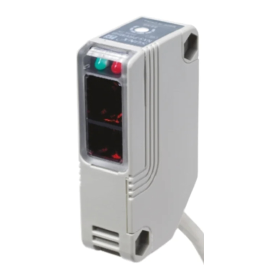
Compact Multi-voltage Photoelectric Sensor Power Supply Built-in
NX5 Series
MJEC-NX5 No.0097-15V
Thank you very much for purchasing Panasonic products.
Read this Instruction Manual carefully and thoroughly for the
correct and optimum use of this product. Kindly keep this
manual in a convenient place for quick reference.
Please refer to "user's manual on our web site ( https://industry.
panasonic.com/ )
Access method is "Download
Model no."
near your sight.
WARNING
Never use this product as a sensing device for personnel protection.
In case of using sensing devices for personnel protection, use products
which meet laws and standards, such as OSHA, ANSI or IEC etc., for
personnel protection applicable in each region or country.
1
PART DESCRIPTION
Operation indicator
Lights up when the output is ON
Stability indicator
Sensing range becomes
L i g h t s u p u n d e r t h e
longer when turned clockwise
stable light condition or
the stable dark condition
Not incorporated on the emitter of NX5-M10R
, the emitter
and receiver of
, or
.
2
MOUNTING
The tightening torque
M4 nuts
screw with washers
less.
Sensor mounting
3
WIRING DIAGRAMS
Color Code
Supply Voltage
+10
C
%
Multi-voltage
-15
Brown
power supply
or
Blue
circuit
+10
C
%
-15
Output relay
Black······N.O.
Note: The emitter of thru-beam
Gray·······N.C.
type sensor has two wires
White······COM.
for the power supply (+V
Internal circuit
4
SENSITIVITY ADJUSTMENT
Step
1. Turn the sensitivity adjuster fully counterclock-
wise to the minimum sensitivity position, MIN.
2. In the light received condition, turn the
sensitivity adjuster slowly clockwise and
A where the sensor en-
ters the "Light" state operation.
3. In the dark condition, turn the sensitivity adjuster further
clockwise until the sensor enters the "Light" state op-
If the sensor does not enter the "Light" state
operation even when the sensitivity adjuster is
turned fully clockwise, the position is point B.
4. The position at the middle of points A
and B is the optimum sensing position.
5
CAUTIONS
This product has been developed / produced for industrial use.
Make sure that the power supply is OFF while wiring.
Take care that wrong wiring will damage the sensor.
Verify that the supply voltage variation is within the rating.
If power is supplied from a commercial switching regula-
power supply is connected to an actual ground.
In case noise generating equipment (switching regulator, inverter
them in the same raceway. This can cause malfunction due to induction.
lamp from a rapid-starter lamp, a high frequency lighting device
the power supply is switched ON.
Extension up to total 100m, (for emitter and receiver of
more conductor area cable.
W h e n c o n n e c t i n g
an inductive load,
Sensor
COM.
connect a surge ab-
.
sorber as shown in
ity for long periods of time. The detection performance may be
This sensor is suitable for indoor use only.
Avoid dust, dirt, and steam.
Take care that the sensor does not come in direct contact
with water, oil, grease, organic solvents, such as, thinner
etc., or strong acid, and alkaline.
product.If adhered to the contact point of the output relay,
contact failure may occur.
The following items are required, as conditions for use in
order to conform to CE Marking / UKCA Marking.
• The output applied voltage should be the same as the
supply voltage of the sensor.
• Be sure to add a short-circuit protection (a fuse or a
A
Panasonic Industry Co., Ltd.
Panasonic Industry Co., Ltd. 2024
B
B where
NX5
Optimum position
A
B
Web
Web
IEC
1
ON
Be sure to
connect a
surge absorp-
tion diode
+
-
N.O.
1
NX5-M10R
N.C.
NX5-M30
-
3
NX5-M10R
2
0.8N m
3
4
1.
2. "
"
PRINTED IN JAPAN
3. "
4. A
5
https://industry.panasonic.com/
OSHA
ANSI
100m
1
3
NX5-M30
•
NX5-RM7
M4
CE
M4
•
•
1
+10
%
-15
(
V,
+10
C
%
-15
N.O.
N.C.
COM.
A
A
Panasonic Industry Co., Ltd. 2024
"
B
"
"
B
B
A
B
B
/
(F.G.)
(
)
(F.G.)
(50ms)
2
0.3mm
(
100
DC
COM.
+
-
N.O.
N.C.
/UKCA
(
)
Advertisement

Related Manuals for Panasonic NX5 Series


Summary of Contents for Panasonic NX5 Series
- Page 1 4. The position at the middle of points A MJEC-NX5 No.0097-15V 4. A and B is the optimum sensing position. Thank you very much for purchasing Panasonic products. Read this Instruction Manual carefully and thoroughly for the CAUTIONS correct and optimum use of this product. Kindly keep this manual in a convenient place for quick reference.
- Page 2 OSHA ANSI IEC F.G. 50 ms 0.3 mm 100 m COM. NX5-M10R NX5-M30 N.O. N.C. NX5-M10R NX5-M30 NX5-RM7 0.8N·m UKCA • • Cr VI N.O. N.C. COM. SJ/T 11364 A ’10 B ’11 J ’19 Panasonic Industry Co., Ltd. 2024...
Need help?
Do you have a question about the NX5 Series and is the answer not in the manual?
Questions and answers