Table of Contents
Advertisement
Quick Links
x950 Switches
Advanced Layer 3+
AlliedWare Plus™ v5.4.9-1
AT-x950-28XSQ Switch
AT-x950-28XTQm Switch
AT-XEM2-12XT Ethernet Line Card
AT-XEM2-12XTm Ethernet Line Card
AT-XEM2-12XS Ethernet Line Card
AT-XEM2-4QS Ethernet Line Card
AT-XEM2-1CQ Ethernet Line Card
AT-PWR600 AC Power Supply
AT-FAN05 Fan Module
Installation Guide for Stand-alone
Switches
613-002642 Rev. B
Advertisement
Table of Contents

Related Manuals for Allied Telesis 950 Series


Summary of Contents for Allied Telesis 950 Series
- Page 1 x950 Switches Advanced Layer 3+ AlliedWare Plus™ v5.4.9-1 AT-x950-28XSQ Switch AT-x950-28XTQm Switch AT-XEM2-12XT Ethernet Line Card AT-XEM2-12XTm Ethernet Line Card AT-XEM2-12XS Ethernet Line Card AT-XEM2-4QS Ethernet Line Card AT-XEM2-1CQ Ethernet Line Card AT-PWR600 AC Power Supply AT-FAN05 Fan Module Installation Guide for Stand-alone Switches 613-002642 Rev.
- Page 2 Allied Telesis, Inc. has been advised of, known, or should have known, the...
- Page 3 Electrical Safety and Emissions Standards This product meets the following standards. U.S. Federal Communications Commission Radiated Energy Note: This equipment has been tested and found to comply with the limits for a Class A digital device pursuant to Part 15 of FCC Rules.
- Page 4 Translated Safety Statements Important: Safety statements that have the symbol are translated into multiple languages in the Translated Safety Statements document at www.alliedtelesis.com/support. Remarque: Les consignes de sécurité portant le symbole sont traduites dans plusieurs langues dans le document Translated Safety Statements, disponible à l'adresse www.alliedtelesis.com/ library.
-
Page 5: Table Of Contents
Contents Preface ....................................11 Document Conventions ...............................12 Contacting Allied Telesis ..............................13 Chapter 1: Overview ................................ 15 x950 Switches ..................................16 Features ....................................18 Hardware Features...............................18 XEM2 Ethernet Line Cards............................18 Management Software and Interfaces .........................19 Management Methods..............................19 Management Panel ..............................19 Power Supplies ................................19 Ports 1 to 24 on the AT-x950-28XSQ Switch ........................20 SFP and SFP+ Transceivers............................20... - Page 6 Contents Designating Ports in the Command Line Interface ......................49 Software and Hardware Releases ............................51 Chapter 2: Beginning the Installation ..........................53 Reviewing Safety Precautions ............................54 Installation Options ................................59 Choosing a Site for the Chassis............................60 Unpacking the Switch ................................. 61 Verifying the Accessory Kit ..............................
- Page 7 Figures Figure 1: Front Panels of the x950 Switches ........................16 Figure 2: Rear Panel of the x950 Switches ..........................17 Figure 3: Link and Activity LEDs for Ports 1 to 24 ........................21 Figure 4: Link and Activity LEDs for Ports 1 to 24 on the AT-x950-28XTQm Switch ............23 Figure 5: QSFP-4SFP10G-3CU and QSFP-4SFP10G-5CU Copper Breakout Cables............24 Figure 6: ET3-MPO08-4LC-5 and ET3-MPO08-4LC-10 Fiber Optic Breakout Cables ............25 Figure 7: LEDs for Ports 25 to 37 ............................25...
- Page 8 Figures Figure 50: Minimum Wall Area Dimensions with the Front Panel on the Left...............95 Figure 51: Minimum Wall Area Dimensions with the Front Panel on the Right ..............96 Figure 52: Switch on the Wall with a Plywood Base ......................97 Figure 53: Steps to Installing the Switch with a Plywood Base.....................98 Figure 54: Installing the Brackets to the Switch for Wall Installation...................102 Figure 55: Attaching the Switch to the Plywood Base ......................104 Figure 56: Marking the Locations of the Bracket Holes on a Concrete Wall...............106...
- Page 9 Tables Table 1: Link and Activity Status LEDs for Ports 1 to 24 .....................21 Table 2: Twisted Pair Ports 1 to 24 on the AT-x950-28XTQm Switch .................22 Table 3: Link and Activity LEDs for Ports 1 to 24 on the AT-x950-28XTQm Switch ............23 Table 4: Link and Activity Status LEDs for 40Gbps QSFP+ or 100Gbps QSFP28 Transceivers ........25 Table 5: Link and Activity Status LEDs for 10Gbps Breakout Cables .................26 Table 6: Port Numbering for Ports 25 to 37 .........................27...
- Page 10 Tables...
-
Page 11: Preface
For instructions on how to build a stack of switches with the VCStack feature, refer to the x950 Series Installation Guide for Virtual Chassis Stacking. This preface contains the following sections: “Document Conventions” on page 12 “Contacting Allied Telesis” on page 13... -
Page 12: Document Conventions
Preface Document Conventions This document uses the following conventions: Note Notes provide additional information. Caution Cautions inform you that performing or omitting a specific action may result in equipment damage or loss of data. Warning Warnings inform you that performing or omitting a specific action may result in bodily injury. -
Page 13: Contacting Allied Telesis
Series Installation Guide for Stand-alone Switches Contacting Allied Telesis If you need assistance with this product, you may contact Allied Telesis technical support by going to the Support & Services section of the Allied Telesis web site at www.alliedtelesis.com/support. You can find links for the following services on this page: ... - Page 14 Preface...
-
Page 15: Chapter 1: Overview
Chapter 1 Overview The chapter contains the following sections: “x950 Switches” on page 16 “Features” on page 18 “Ports 1 to 24 on the AT-x950-28XSQ Switch” on page 20 “Ports 1 to 24 on the AT-x950-28XTQm Switch” on page 22 ... -
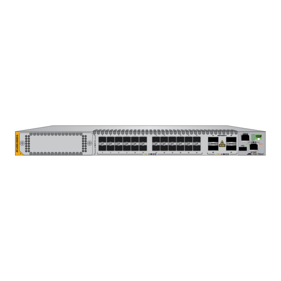
Page 16: X950 Switches
Chapter 1: Overview x950 Switches The front panels of the switches are shown in Figure 1. Management Panel AT-x950-28XSQ Switch Ports 1 to 24: Ports 25, 29, 33, 37: XEM2 Line Card 1Gbps SFP or 10Gbps 40Gbps or 100Gbps Expansion Slot SFP+ Transceivers Transceivers, or 10Gbps Breakout Cables... -
Page 17: Figure 2: Rear Panel Of The X950 Switches
x950 Series Installation Guide for Stand-alone Switches Two Slots for AT-PWR600 Two AT-FAN05 Cooling Fan Power Supply Modules Modules Figure 2. Rear Panel of the x950 Switches... -
Page 18: Features
Chapter 1: Overview Features The main hardware features of the x950 Switches are listed here. Hardware The switch has the following hardware features: Features 1RU height 24 ports on the AT-x950-28XSQ Switch for 1Gbps SFP or 10Gbps SFP+ transceivers. Refer to “Ports 1 to 24 on the AT-x950-28XSQ Switch”... -
Page 19: Management Software And Interfaces
Series Installation Guide for Stand-alone Switches Line cards are ordered separately. Refer to the product data sheet on the Allied Telesis web site for a list of approved transceivers. Management Here are the management software and interfaces: Software and ... -
Page 20: Ports 1 To 24 On The At-X950-28Xsq Switch
They support full-duplex mode only. You can set the port speeds with Auto-Negotiation or manually. The default is Auto-Negotiation. Transceivers must be purchased separately. For a list of supported transceivers, refer to the product data sheet on the Allied Telesis web site. -
Page 21: Leds
x950 Series Installation Guide for Stand-alone Switches LEDs The LEDs are located between the ports. Each port has one LED. Refer to Figure 3. Top Transceiver Port LED Bottom Transceiver Port LED Figure 3. Link and Activity LEDs for Ports 1 to 24 The LEDs displays link and activity status. -
Page 22: Ports 1 To 24 On The At-X950-28Xtqm Switch
Chapter 1: Overview Ports 1 to 24 on the AT-x950-28XTQm Switch The specifications for twisted pair ports 1 to 24 on the AT-x950-28XTQm Switch are listed in Table 2. Table 2. Twisted Pair Ports 1 to 24 on the AT-x950-28XTQm Switch Specification Description Port Speed... -
Page 23: Leds
x950 Series Installation Guide for Stand-alone Switches LEDs This section explains the LEDs for the 1/2.5/5/10Gbps twisted pair ports on the AT-x950-28XTQm Switch. Each port has one LED that displays link and activity information. The LEDs are shown in Figure 4. Top Port LED Bottom Port LED Figure 4. -
Page 24: Ports 25 To 37
Chapter 1: Overview Ports 25 to 37 Ports 25, 29, 33, and 37 support the following types of transceivers and cables: 100Gbps QSFP28 transceivers 40Gbps QSFP+ transceivers 40Gbps to 10Gbps breakout cables QSFP28 The ports support the following 100Gbps QSFP28 transceivers: Transceivers ... -
Page 25: Leds
x950 Series Installation Guide for Stand-alone Switches The fiber optic break-out cables are ET3-MPO08-4LC-5 and ET3-MPO08- 4LC-10, in lengths of 5 and 10 meters, respectively. They have duplex LC connectors. Refer to Figure 6. Figure 6. ET3-MPO08-4LC-5 and ET3-MPO08-4LC-10 Fiber Optic Breakout Cables LEDs The ports have one link and activity status LED each. -
Page 26: Port Numbering
Chapter 1: Overview Table 4. Link and Activity Status LEDs for 40Gbps QSFP+ or 100Gbps QSFP28 Transceivers (Continued) State Description Flashing Amber The transceiver is transmitting or receiving data at 40Gbps. Possible causes of this state are listed here: - The transceiver slot is empty. - The transceiver has not established a link to a network device. -
Page 27: Table 6: Port Numbering For Ports 25 To 37
x950 Series Installation Guide for Stand-alone Switches Table 6. Port Numbering for Ports 25 to 37 With Fiber Optic With Breakout Port Transceiver or Cable Direct Attach Cable port1.0.25 port1.0.25 port1.0.26 port1.0.27 port1.0.28 port1.0.29 port1.0.29 port1.0.30 port1.0.31 port1.0.32 port1.0.33 port1.0.33 port1.0.34 port1.0.35 port1.0.36... -
Page 28: Xem2 Ethernet Line Cards
Chapter 1: Overview XEM2 Ethernet Line Cards The x950 Switches have one expansion slot on the front panel for an optional XEM2 Ethernet line card. The cards are shown in Figure 8 and described in Table 7. AT-XEM2-12XT AT-XEM2-12XTm AT-XEM2-12XS AT-XEM2-4QS AT-XEM2-1CQ Figure 8. - Page 29 x950 Series Installation Guide for Stand-alone Switches Table 7. XEM2 Ethernet Line Cards (Continued) Line Card Description AT-XEM2-12XTm 12 twisted pair ports with RJ-45 connectors that support the following speeds: - 100Mbps - 1/2.5/5/10Gbps Refer to “AT-XEM2-12XTm Line Card” on page 32.
-
Page 30: At-Xem2-12Xt Line Card
Chapter 1: Overview AT-XEM2-12XT Line Card The AT-XEM2-12XT Line Card is shown in Figure 9. Figure 9. AT-XEM2-12XT Line Card RJ-45 Ports The card has 12 twisted pair ports with standard 8-pin RJ-45 ports. The specifications of the ports are listed in Table 8. Table 8. -
Page 31: Leds
x950 Series Installation Guide for Stand-alone Switches Table 8. Twisted Pair Ports on the AT-XEM2-12XT Line Card (Continued) Specification Description Cabling The minimum cable requirements are: - 100Mbps - Standard TIA/EIA 568-B- compliant Category 3 unshielded cabling. - 1Gbps - Standard TIA/EIA 568-A- compliant Category 5 or TIA/EIA 568-B- compliant Enhanced Category 5 (Cat 5e) unshielded cabling. -
Page 32: At-Xem2-12Xtm Line Card
Chapter 1: Overview AT-XEM2-12XTm Line Card The AT-XEM2-12XTm Card is shown in Figure 10. Figure 10. AT-XEM2-12XTm Line Card The AT-XEM2-12XTm Card has 12 twisted pair ports with standard 8-pin RJ-45 ports. The specifications of the ports are listed in Table 10. Table 10. -
Page 33: Table 11: Link And Activity Leds On The At-Xem2-12Xtm Line Card
x950 Series Installation Guide for Stand-alone Switches Table 10. Twisted Pair Ports on the AT-XEM2-12XTm Line Card Specification Description Cabling The minimum cable requirements are: - 100Mbps - Standard TIA/EIA 568-B- compliant Category 3 unshielded cabling. - 1/2.5/5Gbps - Standard TIA/EIA 568-A- compliant Category 5 or TIA/EIA 568-B- compliant Enhanced Category 5 (Cat 5e) unshielded cabling. -
Page 34: At-Xem2-12Xs Line Card
Chapter 1: Overview AT-XEM2-12XS Line Card The AT-XEM2-12XS Line Card is shown in Figure 11. Figure 11. AT-XEM2-12XS Line Card Transceivers The card has twelve ports that support the following types of 1Gbps SFP or 10Gbps SFP+ transceivers: 1Gbps SX or LX SFP transceivers ... -
Page 35: Leds
x950 Series Installation Guide for Stand-alone Switches LEDs The ports have link and activity LEDs. The LED states are described in Table 12. Table 12. Port Link and Activity LEDs on the AT-XEM2-12XS Line Card State Description Solid Green The transceiver has established a 10GBase link to a network device. -
Page 36: At-Xem2-4Qs Line Card
Chapter 1: Overview AT-XEM2-4QS Line Card The AT-XEM2-4QS Line Card is shown in Figure 12. Figure 12. AT-XEM2-4QS Line Card Transceivers The card supports the following types of 40Gbps QSFP+ transceivers in its four ports: QSFPSR4 transceiver - Maximum operating distance of 150 meters (492 feet) with 12-strand OM4 fiber optic cable. -
Page 37: Table 13: Port Link And Activity Status Leds On The At-Xem2-4Qs Line Card
x950 Series Installation Guide for Stand-alone Switches Table 13. Port Link and Activity Status LEDs on the AT-XEM2-4QS Line Card State Description Solid Green The transceiver has established a 40GBase link to a network device. Flashing Green The transceiver is transmitting or receiving data. -
Page 38: At-Xem2-1Cq Line Card
Chapter 1: Overview AT-XEM2-1CQ Line Card The AT-XEM2-1CQ Line Card is shown in Figure 13. Figure 13. AT-XEM2-1CQ Line Card Transceivers The one port on the card supports the following 100Gbps QSFP28 transceivers: QSFP28SR4 transceiver - Maximum operating distance of 70m (230 ft) or 100m (328 ft) with 12-strand OM3 or OM4 fiber optic cable, respectively. -
Page 39: Table 15: Port Link And Activity Status Led On The At-Xem2-1Cq Line Card
x950 Series Installation Guide for Stand-alone Switches Table 15. Port Link and Activity Status LED on the AT-XEM2-1CQ Line Card State Description Solid Green The transceiver has established a link to a network device. Flashing Green The transceiver is transmitting or receiving data. -
Page 40: Management Panel
Chapter 1: Overview Management Panel The components on the management panel are identified in Figure 14. CONSOLE Switch ID RS-232 Serial Port eco-friendly Button USB Slot NET MGMT Port Figure 14. Management Panel Note The management panel is not field-replaceable. USB Port You can use the USB port with a flash drive to perform the following management functions:... -
Page 41: Net Mgmt Ethernet Management Port
x950 Series Installation Guide for Stand-alone Switches configuration file from flash drive. Using a flash drive with the switch is optional. NET MGMT The switch uses the NET MGMT port as a separate routed eth0 interface. The interface is not part of the switching matrix, but the switch can route Ethernet traffic in or out of the port from the network ports and Ethernet line card. -
Page 42: Console (Rs-232) Port
Chapter 1: Overview Table 16. NET MGMT Port LED State Description Flashing Amber The port is transmitting or receiving data at 10 or 100 Mbps. The port has not established a link to a network device. Console (RS-232) You use the Console Port to conduct local management sessions with the switch. -
Page 43: Figure 15: Switch Id Led With The Eco-Friendly Mode Disabled
x950 Series Installation Guide for Stand-alone Switches The switch is booting up. The switch has encountered a fault condition. The VCStack feature is disabled. The switch is operating as a stand-alone unit, with the ID number 1. The switch is a member of a VCStack and has an ID number in the range of 1 to 8. -
Page 44: Eco-Friendly Button
Chapter 1: Overview eco-friendly You use the eco-friendly button on the management panel to turn the LEDs on or off. You might turn off the LEDs when you are not using them Button to monitor the switch, to conserve electricity. When the LEDs are off, the overall power consumption of the chassis is reduced by approximately 2 watts. -
Page 45: Optional Direct Attach Cables
x950 Series Installation Guide for Stand-alone Switches Optional Direct Attach Cables The optional direct attach cables listed in Table 17 offer an economical way to add 10Gbps, 40Gbps, or 100Gbps connections over short distances for switch ports or ports on XEM2 Line Cards. Table 17. -
Page 46: At-Pwr600 Power Supply
Chapter 1: Overview AT-PWR600 Power Supply The AT-PWR600 module is the power supply for the switch. The model name can be found on a label on the release tab on the front panel. Refer to Figure 17. Figure 17. AT-PWR600 Power Supply Here are power supply guidelines: ... -
Page 47: Leds
The power supplies are installed in the PSU A and PSU B slots in the rear panel of the chassis. If you are installing only one power supply, Allied Telesis recommends installing it in PSU A slot because that slot does not come with a blank slot cover. -
Page 48: At-Fan05 Cooling Fan
Chapter 1: Overview AT-FAN05 Cooling Fan The cooling unit for the chassis is the AT-FAN05 fan module. Refer to Figure 18. Figure 18. AT-FAN05 Fan Module Here are the fan module guidelines: The switch comes with two pre-installed fan modules in FAN A and FAN B slots on the rear panel. -
Page 49: Designating Ports In The Command Line Interface
Identifies the switch’s ID number. Please review the following: - The default value is 1. - Allied Telesis recommends using the default value for stand-alone switches. - A stand-alone switch that was previously a stack member retains its ID number from the stack. -
Page 50: Figure 20: Slot Numbers For Port Numbering On Stand-Alone Switches
Chapter 1: Overview Figure 20 identifies the slot numbers for base ports and line card ports. Slot Number 0 for Slot Number 1 for Base Ports: XEM2 Line Card: port1.0.n port1.1.n Figure 20. Slot Numbers for Port Numbering on Stand-alone Switches You have to include the PORT parameter when identifying individual ports, and omit it from the last port when specifying ranges. -
Page 51: Software And Hardware Releases
x950 Series Installation Guide for Stand-alone Switches Software and Hardware Releases The software and hardware releases for the AlliedWare Plus operating software and x950 Switches are listed in Table 20. Table 20. Software and Hardware Releases Hardware / VCStack Software Version AT-x950-28XSQ Switch v5.4.8-2 AT-XEM2-12XT Line Card... - Page 52 Chapter 1: Overview...
-
Page 53: Chapter 2: Beginning The Installation
Chapter 2 Beginning the Installation The chapter contains the following sections: “Reviewing Safety Precautions” on page 54 “Installation Options” on page 59 “Choosing a Site for the Chassis” on page 60 “Unpacking the Switch” on page 61 ... -
Page 54: Reviewing Safety Precautions
Chapter 2: Beginning the Installation Reviewing Safety Precautions Please review the following safety precautions before beginning the installation procedure. Note Safety statements that have the symbol are translated into multiple languages in the Translated Safety Statements document at www.alliedtelesis.com/support. Warning Class 1 Laser product. - Page 55 x950 Series Installation Guide for Stand-alone Switches Warning Power cord is used as a disconnection device. To de-energize equipment, disconnect the power cord. E3 Warning Class I Equipment. This equipment must be earthed. The power plug must be connected to a properly wired earth ground socket outlet.
- Page 56 E25 Warning The chassis may be heavy and awkward to lift. Allied Telesis recommends that you get assistance when mounting the chassis in an equipment rack. E28 Note Use dedicated power circuits or power conditioners to supply reliable electrical power to the device.
- Page 57 x950 Series Installation Guide for Stand-alone Switches Note If installed in a closed or multi-unit rack assembly, the operating ambient temperature of the rack environment may be greater than the room ambient temperature. Therefore, consideration should be given to installing the equipment in an environment compatible with the manufacturer’s maximum rated ambient temperature (Tmra).
- Page 58 Chapter 2: Beginning the Installation Warning The temperature of an operational SFP or SFP+ transceiver may exceed 70° C (158° F). Exercise caution when removing or handling transceivers with unprotected hands. E43 Warning The chassis must be supplied by a grounded three wire AC source through the power supply cord.
-
Page 59: Installation Options
RKMT-SL01 Sliding Shelf is purchased separately. This guide contains instructions for all installation options, except the AT- RKMT-SL01 Sliding Rack Mount Kit. Instructions for the latter are provided in the AT-RKMT-SL01 Sliding Rack Mount Kit Installation Guide on the Allied Telesis web site,... -
Page 60: Choosing A Site For The Chassis
Chapter 2: Beginning the Installation Choosing a Site for the Chassis Observe these site requirements. If you are installing the device in an equipment rack, check that the rack is safely secured so that it will not tip over. Devices should be installed in the rack starting at the bottom, with the heavier devices near the bottom of the rack. -
Page 61: Unpacking The Switch
x950 Series Installation Guide for Stand-alone Switches Unpacking the Switch To unpack the switch from its shipping box, perform the following procedure: 1. Remove the accessories and documents from the accessory box partition. Refer to Figure 22. Figure 22. Removing Accessories 2. -
Page 62: Figure 23: Removing The Shipping Box Partition
Chapter 2: Beginning the Installation Figure 23. Removing the Shipping Box Partition 3. Lift the switch from the shipping box and place it on a level, secure table. Refer to Figure 24 on page 63. Warning The switch is heavy. Ask for assistance lifting the device out of the shipping box. -
Page 63: Figure 24: Lifting The Switch From The Shipping Box
x950 Series Installation Guide for Stand-alone Switches Figure 24. Lifting the Switch from the Shipping Box 4. Remove the switch from the shipping end-caps and protective bag. Refer to Figure 25. Figure 25. Removing the Switch from the Shipping End-caps and Protective Bag... - Page 64 Chapter 2: Beginning the Installation 5. Visually inspect the product for damage. 6. Visually inspect the front panel for the components shown in Figure 1 on page 16. 7. Verify that there are two pre-installed fan modules in FAN A and FAN B slots on the rear panel.
-
Page 65: Verifying The Accessory Kit
x950 Series Installation Guide for Stand-alone Switches Verifying the Accessory Kit Figure 26 lists the accessory items that are included with the switch. One 2 m (6.6 ft) local management cable with RJ-45 (8P8C) and DB-9 (D-sub 9-pin) connectors. Sixteen bracket screws Four standard equipment rack or wall mounting brackets Four anchors for concrete... - Page 66 Chapter 2: Beginning the Installation Note If any item is missing or damaged, contact your Allied Telesis sales representative for assistance. After unpacking the switch and verifying the accessory kit, go to “Unpacking the AT-PWR600 AC Power Supply” on page 67.
-
Page 67: Unpacking The At-Pwr600 Ac Power Supply
x950 Series Installation Guide for Stand-alone Switches Unpacking the AT-PWR600 AC Power Supply To unpack the AT-PWR600 Power Supply, perform the following procedure: 1. Remove the power cord and any documents from the accessory box partition. Refer to Figure 27. Figure 27. -
Page 68: Figure 28: Removing The Partition From The At-Pwr600 Ac Power Supply Shipping Box
Chapter 2: Beginning the Installation Figure 28. Removing the Partition from the AT-PWR600 AC Power Supply Shipping Box 3. Lift the power supply from the shipping box and place it on a level, secure table. Refer to Figure 29 on page 69. Warning The power supply is heavy. -
Page 69: Figure 29: Removing The Power Supply From The Shipping Box
x950 Series Installation Guide for Stand-alone Switches Figure 29. Removing the Power Supply from the Shipping Box 4. Remove the power supply from the shipping end-caps and protective shipping bag. Refer to Figure 30. Figure 30. Removing the Power Supply from the Shipping End-caps and Protective Bag 5. - Page 70 Chapter 2: Beginning the Installation...
-
Page 71: Chapter 3: Installing Power Supplies And Optional Xem2 Line Card
Chapter 3 Installing Power Supplies and Optional XEM2 Line Card This chapter has the following procedures: “Installing AT-PWR600 AC Power Supplies” on page 72 “Installing an Optional XEM2 Ethernet Line Card” on page 76... -
Page 72: Installing At-Pwr600 Ac Power Supplies
PSU A and PSU B on the left side of the rear panel. If you are installing only one power supply, you can install it in either slot. Allied Telesis recommends PSU A because that slot does not come with a blank power supply panel. -
Page 73: Figure 31: Removing The Blank Power Supply Panel From Slot Psu B
x950 Series Installation Guide for Stand-alone Switches Release Tab Figure 31. Removing the Blank Power Supply Panel from Slot PSU B 3. Carefully align the power supply in the slot and slide it into the slot. Figure 32 on page 74 shows the module aligned for the PSU A slot. -
Page 74: Figure 32: Sliding The At-Pwr600 Ac Power Supply Into The Chassis
Chapter 3: Installing Power Supplies and Optional XEM2 Line Card Figure 32. Sliding the AT-PWR600 AC Power Supply into the Chassis 4. When the power supply makes contact with the connector inside the switch, gently press on its faceplate to seat it on the connector. Refer to Figure 33 on page 75. -
Page 75: Figure 33: Seating The Power Supply On The Internal Connector
x950 Series Installation Guide for Stand-alone Switches Figure 33. Seating the Power Supply on the Internal Connector 5. Visually inspect the power supply to be sure that its faceplate is flush against the rear panel of the chassis. 6. If you purchased two power supplies for the switch, repeat this procedure to install the second unit. -
Page 76: Installing An Optional Xem2 Ethernet Line Card
Chapter 3: Installing Power Supplies and Optional XEM2 Line Card Installing an Optional XEM2 Ethernet Line Card This section contains the procedure for installing an optional XEM2 Ethernet line card in the expansion slot in the front panel of the switch. For background information, refer to “XEM2 Ethernet Line Cards”... -
Page 77: Figure 35: Removing The Ethernet Line Card From The Anti-Static Bag
x950 Series Installation Guide for Stand-alone Switches Figure 35. Removing the Ethernet Line Card from the Anti-static Bag 3. Position the line card with the notch on the faceplate in the bottom left corner, as shown in Figure 36, and carefully slide it into the slot. Notch Figure 36. -
Page 78: Figure 37: Seating The Ethernet Line Card In The Expansion Slot
Chapter 3: Installing Power Supplies and Optional XEM2 Line Card 4. When the line card makes contact with the internal connector in the switch. gently press on the sides of its faceplate to seat it on the connector. Refer to Figure 37. Figure 37. -
Page 79: Figure 38: Tightening The Two Captive Screws On The Ethernet Line Card
x950 Series Installation Guide for Stand-alone Switches Figure 38. Tightening the Two Captive Screws on the Ethernet Line Card 7. After installing the power supplies and optional XEM2 Line Card, go to one of the following chapters: Chapter 4, “Installing the Switch on a Table” on page 81 ... - Page 80 Chapter 3: Installing Power Supplies and Optional XEM2 Line Card...
-
Page 81: Chapter 4: Installing The Switch On A Table
Chapter 4 Installing the Switch on a Table This chapter contains the instructions for installing the switch on a table or desktop. Warning Switches should not be stacked on a table or desktop. They could present a physical safety hazard if you need to move or replace switches. -
Page 82: Figure 40: Holes For Bumper Feet
Chapter 4: Installing the Switch on a Table Rear of Chassis Front of Chassis Figure 40. Holes for Bumper Feet Note The following procedure assumes that you have already reviewed the information and performed the procedures in Chapter 2, “Beginning the Installation” on page 53. To install the switch on a table, perform the following procedure: 1. -
Page 83: Figure 42: Placing The Bumper Foot On A Base Corner Hole
x950 Series Installation Guide for Stand-alone Switches 3. Place the bumper foot onto one of the holes in the base of the switch. Refer to Figure 42. Figure 42. Placing the Bumper Foot on a Base Corner Hole 4. Insert the rivet to secure the bumper foot to the base. Refer to Figure 43. - Page 84 Chapter 4: Installing the Switch on a Table 7. Do one of the following: To install power supplies, go to “Installing AT-PWR600 AC Power Supplies” on page 72. To install an optional XEM2 Ethernet Line Card, go to “Installing an Optional XEM2 Ethernet Line Card”...
-
Page 85: Chapter 5: Installing The Switch In An Equipment Rack
Chapter 5 Installing the Switch in an Equipment Rack This chapter contains instructions for installing the switch in a standard 19- inch equipment rack. The procedures are listed here: “Beginning the Installation” on page 86 “Removing the Bumper Feet” on page 88 ... -
Page 86: Beginning The Installation
Chapter 5: Installing the Switch in an Equipment Rack Beginning the Installation This chapter contains the procedure for installing the switch in a standard 19-inch equipment rack, with the brackets included with the unit. Required Items The following items are required to install the switch in an equipment rack: ... -
Page 87: Figure 45: Switch Orientations In An Equipment Rack
x950 Series Installation Guide for Stand-alone Switches Figure 45. Switch Orientations in an Equipment Rack... -
Page 88: Removing The Bumper Feet
Chapter 5: Installing the Switch in an Equipment Rack Removing the Bumper Feet The bumper feet included with the switch should not be used when installing the device in an equipment rack. If they are already installed, perform the following procedure to remove them: 1. -
Page 89: Installing The Switch
Please review the information and perform the procedures in Chapter 2, “Beginning the Installation” on page 53 before installing the switch. Caution The chassis may be heavy and awkward to lift. Allied Telesis recommends that you get assistance when mounting the chassis in an equipment rack. E28... -
Page 90: Figure 47: Attaching The Equipment Rack Brackets
Chapter 5: Installing the Switch in an Equipment Rack Figure 47. Attaching the Equipment Rack Brackets 4. Have another person hold the switch in the equipment rack while you secure it using standard equipment rack screws (not provided). Refer to Figure 48. Figure 48. - Page 91 x950 Series Installation Guide for Stand-alone Switches 5. Do one of the following: To install power supplies, go to “Installing AT-PWR600 AC Power Supplies” on page 72. To install an optional XEM2 Ethernet Line Card, go to “Installing an Optional XEM2 Ethernet Line Card”...
- Page 92 Chapter 5: Installing the Switch in an Equipment Rack...
-
Page 93: Chapter 6: Installing The Switch On A Wall
Chapter 6 Installing the Switch on a Wall The procedures in this chapter are listed here: “Switch Orientations on a Wall” on page 94 “Recommended Minimum Wall Area Dimensions” on page 95 “Plywood Base for a Wall with Wooden Studs” on page 97 ... -
Page 94: Switch Orientations On A Wall
Chapter 6: Installing the Switch on a Wall Switch Orientations on a Wall You can install the switch on a wall with the front panel on the left or right, as shown in Figure 49. Do not install it with the front panel on the top or bottom. -
Page 95: Recommended Minimum Wall Area Dimensions
x950 Series Installation Guide for Stand-alone Switches Recommended Minimum Wall Area Dimensions The recommended minimum dimensions for the reserved wall area for the switch are listed here: Width: 96 centimeters (36 inches) Height: 58 centimeters (23 inches) Figure 50 and Figure 51 on page 96 illustrate the recommended positions of the switch in the reserved area when the front panel is on the left and right, respectively. -
Page 96: Figure 51: Minimum Wall Area Dimensions With The Front Panel On The Right
Chapter 6: Installing the Switch on a Wall Figure 51. Minimum Wall Area Dimensions with the Front Panel on the Right... -
Page 97: Plywood Base For A Wall With Wooden Studs
x950 Series Installation Guide for Stand-alone Switches Plywood Base for a Wall with Wooden Studs If you are installing the switch on a wall that has wooden studs, Allied Telesis recommends using a plywood base for the device. (A plywood base is not required for a concrete wall.) Refer to Figure 52. -
Page 98: Figure 53: Steps To Installing The Switch With A Plywood Base
Chapter 6: Installing the Switch on a Wall brackets on the switch is 37 centimeters (14 1/2 inches). The recommended minimum dimensions of the plywood base are listed here: Width: 58.4 centimeters (23 inches) Height: 55.9 centimeters (22 inches) ... -
Page 99: Installation Guidelines
x950 Series Installation Guide for Stand-alone Switches Installation Guidelines Here are the guidelines to installing the switch on a wall: You may install the switch on a wall that has wooden studs. You may install it on a concrete wall. ... - Page 100 Chapter 6: Installing the Switch on a Wall Cross-head screwdriver (not provided) Stud finder for a wooden wall, capable of identifying the middle of wall studs and hot electrical wiring (not provided) Drill and 1/4” carbide drill bit for a concrete wall (not provided) ...
-
Page 101: Installing The Plywood Base
x950 Series Installation Guide for Stand-alone Switches Installing the Plywood Base A plywood base is recommended when installing the switch on a wall that has wooden studs. Refer to “Plywood Base for a Wall with Wooden Studs” on page 97. Consult a qualified building contractor for installation instructions for the plywood base. -
Page 102: Installing The Switch On The Plywood Base
This procedure assumes that the plywood base for the switch is already installed on the wall. Please review “Reviewing Safety Precautions” on page 54 and “Choosing a Site for the Chassis” on page 60 before performing this procedure. Allied Telesis recommends a minimum of three people for this procedure. Warning The device is heavy. - Page 103 x950 Series Installation Guide for Stand-alone Switches The sides of the switch have two sets of holes. One set is for installing the switch on a wall with the brackets and the other is for the AT- RKMT-SL01 Rack Mounting Kit. For this procedure, you need to use the bracket holes, identified in Figure 44 on page 86.
-
Page 104: Figure 55: Attaching The Switch To The Plywood Base
Chapter 6: Installing the Switch on a Wall Figure 55. Attaching the Switch to the Plywood Base 4. Do one of the following: To install the power supplies, go to “Installing AT-PWR600 AC Power Supplies” on page 72. To install an optional XEM2 Ethernet Line Card, go to “Installing an Optional XEM2 Ethernet Line Card”... -
Page 105: Installing The Switch On A Concrete Wall
Series Installation Guide for Stand-alone Switches Installing the Switch on a Concrete Wall Allied Telesis recommends a minimum of three people for this procedure. To install the switch on a concrete wall, perform the following procedure: Warning The device is heavy. Always ask for assistance before moving or lifting it to avoid injuring yourself or damaging the equipment. -
Page 106: Figure 56: Marking The Locations Of The Bracket Holes On A Concrete Wall
3. Please review the following guidelines: Prior to drilling, set the drill to hammer and rotation mode. The modes break up the concrete and clean out the hole. Allied Telesis recommends cleaning out the holes with a brush or compressed air. -
Page 107: Figure 57: Installing The Switch On A Concrete Wall
x950 Series Installation Guide for Stand-alone Switches 6. Insert the four anchors into the holes. 7. Have two people hold the switch at the selected wall location while you secure it to the wall with the four provided screws. Refer to Figure 57. Figure 57. - Page 108 Chapter 6: Installing the Switch on a Wall...
-
Page 109: Chapter 7: Verifying And Configuring The Switch
Chapter 7 Verifying and Configuring the Switch This chapter contains the following procedures: “Powering On the Switch” on page 110 “Starting a Local Management Session” on page 113 “Verifying the Switch with AlliedWare Plus Commands” on page 115 ... -
Page 110: Powering On The Switch
Chapter 7: Verifying and Configuring the Switch Powering On the Switch The procedure in this section explains how to power on the switch. If you have not installed the power supplies, refer to “Installing AT-PWR600 AC Power Supplies” on page 72 for instructions. Before powering on the chassis, review the information in “Power Specifications”... -
Page 111: Figure 58: Connecting The Ac Power Cord
x950 Series Installation Guide for Stand-alone Switches Figure 58. Connecting the AC Power Cord 2. Move the power cord into the restraining strap and secure the strap by feeding it into the tab slot. Refer to Figure 59. Tab Slot Figure 59. -
Page 112: Figure 60: Connecting The Power Cord To An Ac Power Source
Chapter 7: Verifying and Configuring the Switch Figure 60. Connecting the Power Cord to an AC Power Source Note The illustration shows the North American power cord. Your power cord may be different. 4. If the switch has two power supplies, repeat this procedure to connect a power cord to the second power supply. -
Page 113: Starting A Local Management Session
x950 Series Installation Guide for Stand-alone Switches Starting a Local Management Session After powering on the switch and waiting two minutes for it to initialize its management software, start a local management session using the Console port on the management panel, as explained in this section. Note The first management session of the switch can be either a local session, as explained in this section, or a remote session over your... -
Page 114: Figure 62: User Exec Mode Prompt
Chapter 7: Verifying and Configuring the Switch 3. Configure the VT-100 terminal or terminal emulation program as follows: Baud rate: 9600 bps Data bits: 8 Parity: None Stop bits: 1 Flow controller: None Note The port settings are for a DEC VT100 or ANSI terminal, or an equivalent terminal emulator program. -
Page 115: Verifying The Switch With Alliedware Plus Commands
3. Check the Status column. All components should have the status “OK.” For information about the command line interface, refer to the Software Reference for AT-x950 Switches on the Allied Telesis web site. 4. Go to “Disabling VCStack” on page 116. -
Page 116: Disabling Vcstack
Chapter 7: Verifying and Configuring the Switch Disabling VCStack The procedure in this section explains how to disable the VCStack feature so that you can use the unit as a stand-alone switch. In all likelihood you will not have to perform this procedure because the default setting for the feature is disabled. -
Page 117: Figure 64: Moving To The Global Configuration Mode
x950 Series Installation Guide for Stand-alone Switches 5. Review the following items: If the Operational Status is “Stacking Hardware Disabled,” the VCStack feature is already disabled on the switch. Go to “Configuring Ports 25 to 37” on page 119. ... -
Page 118: Figure 67: Saving The Changes With The Write Command
Chapter 7: Verifying and Configuring the Switch 10. Enter the WRITE command to save your change in the configuration file. The switch displays the confirmation prompt in Figure 67. awplus# write Building configuration ... [OK] awplus# Figure 67. Saving the Changes with the WRITE Command If this is the first management session, the switch automatically creates the Default.cfg file in flash memory to store your changes. -
Page 119: Configuring Ports 25 To 37
x950 Series Installation Guide for Stand-alone Switches Configuring Ports 25 to 37 Ports 25, 29, 33, and 37 support the following transceivers and cables: 40Gbps QSFP+ transceivers 100Gbps QSFP28 transceivers 40Gbps to 10Gbps copper and fiber optic breakout cables You have to configure the ports for the transceivers with the PLATFORM PORTMODE INTERFACE command in the Global Configuration mode. - Page 120 Chapter 7: Verifying and Configuring the Switch This example configures ports 33 and 37 for 100Gbps QSFP28 transceivers: awplus(config)# platform portmode interface port1.0.33, port1.0.37 100g This example configures port 25 for a breakout cable: awplus(config)# platform portmode interface port1.0.25 10gx4 This example configures ports 25 and 29 for 40Gbps QSFP+ transceivers: awplus(config)# platform portmode interface...
-
Page 121: Saving Your Changes And Rebooting The Switch
x950 Series Installation Guide for Stand-alone Switches Saving Your Changes and Rebooting the Switch After disabling the VCStack feature or configuring ports 25 to 37, you have to save your configuration changes and reboot the switch, as explained in the following procedure: 1. - Page 122 Chapter 7: Verifying and Configuring the Switch...
-
Page 123: Chapter 8: Cabling The Networking Ports
Chapter 8 Cabling the Networking Ports This chapter contains the following procedures: “Cabling Twisted Pair Ports” on page 124 “Guidelines to Handling Twisted Pair or Fiber Optic Transceivers” on page 125 “Installing Transceivers” on page 126 “Installing Direct Attach Cables”... -
Page 124: Cabling Twisted Pair Ports
Chapter 8: Cabling the Networking Ports Cabling Twisted Pair Ports This section applies to the 1/10Gbps twisted pair ports on AT-XEM2-12XT Line Cards and 1/2.5/5/10Gbps ports on AT-XEM2-12XTm Line Cards. Here are the cabling guidelines: The cable specifications for AT-XEM2-12XT and AT-XEM2-12XTm Line Cards are listed in Table 8 on page 30 and Table 10 on page 32, respectively. -
Page 125: Guidelines To Handling Twisted Pair Or Fiber Optic Transceivers
For a list of supported transceivers, refer to the product data sheet on the Allied Telesis web site. The operational specifications and fiber optic cable requirements are provided in the documents included with the transceivers. -
Page 126: Installing Transceivers
Chapter 8: Cabling the Networking Ports Installing Transceivers Table 21 lists the types of transceivers supported by the base transceiver slots. Refer to the product data sheet for a list of approved transceivers. Table 21. Transceivers for the Base Transceiver Slots Base Ports Fiber Optic Transceiver Ports 1 to 24 on the... -
Page 127: Figure 71: Sp10T Transceivers
x950 Series Installation Guide for Stand-alone Switches Table 21. Transceivers for the Base Transceiver Slots (Continued) Base Ports Fiber Optic Transceiver - AT-QSFP1CU and AT-QSFP3CU direct Base ports 25, 29, 33, and attach cables in lengths of 1 and 3 37 (Continued) meters, respectively. - Page 128 Chapter 8: Cabling the Networking Ports Table 22. Transceivers for the Optional XEM2 Ethernet Line Cards Ethernet Line Card Transceiver AT-XEM2-4QS 40Gbps QSFP+ transceivers: - QSFPSR4 fiber optic transceiver - Maximum operating distance of 150 meters (492 feet) with 12-strand OM4 fiber optic cable.
-
Page 129: Figure 72: Installing An Sfp Or Sfp+ Transceiver
x950 Series Installation Guide for Stand-alone Switches To install a fiber optic transceiver, perform the following procedure: 1. Select a port for the transceiver. 2. If the selected port has a dust cover, remove it. 3. Remove the transceiver from its shipping container and store the packaging material in a safe location. -
Page 130: Figure 73: Installing 40Gbps Fiber Optic Transceivers In At-Xem2-4Qs Line Cards
Chapter 8: Cabling the Networking Ports Figure 73. Installing 40Gbps Fiber Optic Transceivers in AT-XEM2-4QS Line Cards 100Gbps QSFP28 transceivers for base ports 25 to 37: refer to Figure 74. Figure 74. Installing 100Gbps QSFP28 Transceivers in Base Ports 25 to ... -
Page 131: Figure 75: Installing 100Gbps Qsfp28 Transceivers In At-Xem2-1Cq Line Cards
x950 Series Installation Guide for Stand-alone Switches Figure 75. Installing 100Gbps QSFP28 Transceivers in AT-XEM2-1CQ Line Cards Note If you are ready to attach the fiber optic cable to the transceiver, continue with the next step. Otherwise, repeat steps 1 to 4 to install additional transceivers. -
Page 132: Installing Direct Attach Cables
Chapter 8: Cabling the Networking Ports Installing Direct Attach Cables Table 17 on page 45 lists the direct attach cables for the base ports and XEM2 Line Cards. They offer an economical way to add 10Gbps, 40Gbps, or 100Gbps connections over short distances. To install direct attach cables, perform the following procedure: 1. -
Page 133: Figure 77: Attaching Qsfpcu Cables
x950 Series Installation Guide for Stand-alone Switches Release Tab Figure 77. Attaching QSFPCU Cables 5. Connect the other end of the cable into a compatible port on another network device. 6. Repeat this procedure to install additional direct attach cables. Note To remove a cable from the port, gently push on the connector, pull on the release tab, and slide the connector from the port. - Page 134 Chapter 8: Cabling the Networking Ports...
-
Page 135: Chapter 9: Replacing Modules
Chapter 9 Replacing Modules This chapter contains the following procedures: “Replacing XEM2 Ethernet Line Cards” on page 136 “Replacing AT-PWR600 AC Power Supplies” on page 141 “Replacing FAN05 Modules” on page 146... -
Page 136: Replacing Xem2 Ethernet Line Cards
An XEM2 line card might require up to thirty seconds before becoming fully operational after being powered on. Note Allied Telesis recommends saving a backup copy of the configuration file in the switch before removing or replacing line cards. For instructions, refer to the Software Reference for x950 Switch, AlliedWare Plus Operating System. -
Page 137: Figure 78: Loosening The Screws On The Ethernet Line Card
x950 Series Installation Guide for Stand-alone Switches Note 100Gbps transceivers for the AT-XEM2-1CQ line card have handles. Always use the handles when installing or removing transceivers. 4. Use a #2 Phillips-head screwdriver to loosen the two screws on the faceplate of the card. Refer to Figure 78. Figure 78. -
Page 138: Figure 79: Disconnecting An Ethernet Line Card From The Switch
Chapter 9: Replacing Modules Figure 79. Disconnecting an Ethernet Line Card from the Switch 6. Carefully slide the card from the switch. Refer to Figure 80. Figure 80. Sliding an Ethernet Line Card from the Switch 7. If you are not installing the line card in another switch, store it in its anti-static bag and shipping container. -
Page 139: Figure 81: Placing The Ethernet Line Card In Its Anti-Static Bag
x950 Series Installation Guide for Stand-alone Switches Figure 81. Placing the Ethernet Line Card in its Anti-static Bag 8. Do one of the following: For instructions on how to install another card in the slot, start with step 2 in “Installing an Optional XEM2 Ethernet Line Card” on page 76. -
Page 140: Figure 83: Tightening The Two Screws On The Line Card Blank Panel
Chapter 9: Replacing Modules Figure 83. Tightening the Two Screws on the Line Card Blank Panel... -
Page 141: Replacing At-Pwr600 Ac Power Supplies
PSU A. The procedure is the same for replacing a power supply in slot PSU B. Note Allied Telesis recommends saving a backup copy of the configuration file in the switch before removing or replacing power supplies. For instructions, refer to the Software Reference for x950 Switch, AlliedWare Plus Operating System. -
Page 142: Figure 85: Opening The Restraining Strap On The Power Supply
Chapter 9: Replacing Modules Release Tab Figure 85. Opening the Restraining Strap on the Power Supply 3. Disconnect the power cord from the power supply. Refer to Figure 86. Figure 86. Disconnecting the Power Cord from the Power Supply... -
Page 143: Figure 87: Removing The Power Supply
x950 Series Installation Guide for Stand-alone Switches 4. Press the release lever to the right and pull on the handle to release the power supply from the internal connector in the switch. Release Lever Figure 87. Removing the Power Supply 5. -
Page 144: Figure 88: Removing A Power Supply
Chapter 9: Replacing Modules Figure 88. Removing a Power Supply 6. Do one of the following: To install a new power supply, refer to “Installing AT-PWR600 AC Power Supplies” on page 72 for instructions. If you are not installing a new power supply, continue with the next step to install the blank panel 7. -
Page 145: Figure 89: Installing The Blank Power Supply Cover
x950 Series Installation Guide for Stand-alone Switches Figure 89. Installing the Blank Power Supply Cover... -
Page 146: Replacing Fan05 Modules
For background information, refer to “AT-FAN05 Cooling Fan” on page 48. Note Allied Telesis recommends saving a backup copy of the configuration file in the switch before replacing a fan module. For instructions, refer to the Software Reference for x950 Switches. -
Page 147: Figure 91: Disconnecting The Fan05 Module From The Switch
x950 Series Installation Guide for Stand-alone Switches 2. Carefully pull on the handle to disconnect the line card from the internal connector in the switch. Refer to Figure 91. Figure 91. Disconnecting the FAN05 Module from the Switch 3. Slide the fan module out of the switch. Refer to Figure 92. Figure 92. -
Page 148: Installing Fan Modules
Chapter 9: Replacing Modules Installing Fan This procedure requires the following tool: Modules #2 Phillips-head screwdriver (not provided) The illustrations show the installation of a fan module in FAN B slot on the back panel. The procedure is the same for installing a module in FAN A slot. -
Page 149: Figure 94: Aligning The Fan05 Module In The Switch Slot
x950 Series Installation Guide for Stand-alone Switches Figure 94. Aligning the FAN05 Module in the Switch Slot 3. When you feel the module make contact with the internal connector, gently press on both sides to seat the module on the connector. Refer to Figure 95. -
Page 150: Figure 96: Tightening The Two Captive Screws On The Fan05 Module
Chapter 9: Replacing Modules Figure 96. Tightening the Two Captive Screws on the FAN05 Module 5. To confirm the operations of the new fan module, start a local or remote management session and enter the SHOW SYSTEM ENVIRONMENT command in the User Exec or Privileged Exec mode. For directions, refer to “Verifying the Switch with AlliedWare Plus Commands”... -
Page 151: Chapter 10: Troubleshooting
This chapter contains suggestions on how to troubleshoot problems with the switch. Note For further assistance, please contact Allied Telesis Technical Support at www.alliedtelesis.com/support. Problem 1: The unit is not receiving power. All the port LEDs and Switch ID LED are off, and the fans are not operating. - Page 152 Chapter 10: Troubleshooting Solutions: Try the following: Check that the transceiver is fully inserted in the port. Verify that the fiber optic cable is securely connected to the port on the transceiver and the remote network device. Verify that the remote network device is operating properly.
- Page 153 Try installing a different card in the switch. If the replacement card fails to work, the problem is probably with the switch. Contact your Allied Telesis sales representative for assistance. Problem 7: An SFP, SFP+, or QSFP+ transceiver in an XEM2 line card is unable to establish a link to another network device.
- Page 154 Chapter 10: Troubleshooting 100Mbps and 1/2.5/5/10Gbps. The cards do not support 10Mbps devices. If the AT-XEM2-12XT Card cannot establish links with 100Mbps devices, the switch might have an earlier version of the AlliedWare Plus management software. Support for 100Mbps devices on the AT-XEM2-12XT Card was added in version 5.4.9-1.
- Page 155 Solutions: One of the following problems has occurred: A cooling fan has failed. The internal temperature of the switch is outside the normal operating range and the unit might shut down. Contact your Allied Telesis sales representative for assistance.
- Page 156 Chapter 10: Troubleshooting...
-
Page 157: Appendix A: Technical Specifications
Appendix A Technical Specifications This appendix contains the following sections: ”Physical Specifications” on page 158 ”Environmental Specifications” on page 160 ”Power Specifications” on page 161 ”Certifications” on page 164 ”RJ-45 Twisted Pair Port Pinouts on AT-XEM2-12XT and AT-XEM2- 12XTm Cards”... -
Page 158: Physical Specifications
Appendix A: Technical Specifications Physical Specifications Dimensions (H x W x D) Table 23 lists the dimensions of the switches and power supplies. Table 23. Product Dimensions AT-x950-28XSQ 4.4 cm x 44.0 cm x 44.5 cm (1.7 in. x 17.3 in. x 17.5 in.) AT-x950-28XTQm 4.4 cm x 44.0 cm x 44.5 cm (1.7 in. -
Page 159: Table 25: Ventilation Requirements
x950 Series Installation Guide for Stand-alone Switches Ventilation Table 25 lists the ventilation requirements. Table 25. Ventilation Requirements Recommended Minimum 10 cm (4.0 in) Ventilation on All Sides... -
Page 160: Environmental Specifications
Appendix A: Technical Specifications Environmental Specifications Table 26 lists the environmental specifications of the switches. Table 26. Environmental Specifications Operating Temperature 0° C to 45° C (32° F to 113° F) (with QSFP28 transceivers) Operating Temperature 0° C to 50° C (32° F to 122° F) (without QSFP28 transceivers) Storage Temperature -25°... -
Page 161: Power Specifications
x950 Series Installation Guide for Stand-alone Switches Power Specifications This section contains the maximum power consumption values and input voltages. Maximum Power Consumptions Table 27 list the maximum power consumptions. Table 27. Maximum Power Consumptions (Watts) AT-x950-28XSQ Switch with one 206.08 W AT-PWR600 Power Supply (no line card) -
Page 162: Table 29: Input Voltages
Appendix A: Technical Specifications Table 28. Typical Power Savings in eco-friendly Mode (Watts) (Continued) AT-XEM2-4QS Line Card 0.11 W AT-XEM2-1CQ Line Card 0.02 W Input Voltage Table 29 lists the input voltage for the power supply. Table 29. Input Voltages AT-x950-28XSQ Switch 100-240 VAC , 2A maximum,... - Page 163 x950 Series Installation Guide for Stand-alone Switches Table 31. Heat Dissipations (British Thermal Units/Hour) (Continued) AT-XEM2-12XTm Line Card 101.81 BTU/hr AT-XEM2-12XS Line Card 103.43 BTU/hr AT-XEM2-4QS Line Card 55.08 BTU/hr AT-XEM2-1CQ Line Card 22.90 BTU/hr AT-PWR600 Power Supply 5118.21 BTU/hr...
-
Page 164: Certifications
Appendix A: Technical Specifications Certifications Table 32 lists the product certificates. Table 32. Product Certifications EMI (Emissions) FCC Class A CISPR 22 Class A EN 55032 Class A VCCI Class A ICES-003 Class A EAC Certification EMC (Immunity) EN 55024 EN 61000-3-2 EN 61000-3-3 Electrical and Laser Safety... -
Page 165: Twisted Pair Port Pinouts On At-Xem2-12Xt And At-Xem2-12Xtm Cards
x950 Series Installation Guide for Stand-alone Switches RJ-45 Twisted Pair Port Pinouts on AT-XEM2-12XT and AT-XEM2- 12XTm Cards Figure 97 illustrates the pin layout of the RJ-45 connectors on the AT- XEM2-12XT and AT-XEM2-12XTm Line Cards. Figure 97. Pin Layout (Front View) of the Ports on the AT-XEM2-12XT and AT-XEM2-12XTm Line Cards Table 33 lists the pin signals. -
Page 166: Rj-45 Style Serial Console Port Pinouts
Appendix A: Technical Specifications RJ-45 Style Serial Console Port Pinouts Table 34 lists the pin signals of the RJ-45 style serial Console port. Table 34. RJ-45 Style Serial Console Port Pin Signals Signal Looped to pin 8. Looped to pin 7. Transmit Data Ground Ground...
Need help?
Do you have a question about the 950 Series and is the answer not in the manual?
Questions and answers