
Related Manuals for Allied Telesis FS750 SERIES


Summary of Contents for Allied Telesis FS750 SERIES
-
Page 1: Installation Guide
FS750 Series FAST ETHERNET WEB-SMART SWITCHES AT-FS750/20 AT-FS750/28 AT-FS750/28PS AT-FS750/52 Installation Guide 613-002095 Rev. B... - Page 2 Telesis, Inc. be liable for any incidental, special, indirect, or consequential damages whatsoever, including but not limited to lost profits, arising out of or related to this manual or the information contained herein, even if Allied Telesis, Inc. has been...
- Page 3 Electrical Safety and Emissions Standards This section contains the following: “US Federal Communications Commission” “Industry Canada” “Emissions, Immunity and Electrical Safety Standards” on page 4 “Translated Safety Statements” on page 4 US Federal Communications Commission Radiated Energy Note This equipment has been tested and found to comply with the limits for a Class A digital device pursuant to Part 15 of FCC Rules.
-
Page 4: Translated Safety Statements
Electrical Safety EN60950-1 (TUV), UL 60950-1 ( Warning Laser Safety: EN60825 Translated Safety Statements Important: The indicates that translations of the safety statement are available in the PDF document “Translated Safety Statements” posted on the Allied Telesis website at alliedtelesis.com/support. -
Page 5: Table Of Contents
Contents Symbol Conventions ............................ 8 Contacting Allied Telesis..........................9 Chapter 1: Overview ............................11 Features ..............................12 Twisted-Pair Ports ..........................12 SFP Slots............................. 12 LEDs..............................13 Installation Options ..........................13 MAC Address Table ..........................13 Switch Front Panels ........................... 14 AT-FS750/20 Model .......................... - Page 6 Contents Environmental Specifications ........................46 Power Specifications ..........................46 Safety and Electromagnetic Emissions Certifications ................46 Connectors and Port Pinouts........................48...
- Page 7 Preface This manual is the installation guide for the FS750 Series Fast Ethernet switches. The switches included in this series are: AT-FS750/20 AT-FS750/28 AT-FS750/28PS AT-FS750/52 This preface includes the following sections: “Symbol Conventions” on page 8 ...
-
Page 8: Symbol Conventions
Symbol Conventions This document uses the following conventions: Note Notes provide additional information. Caution Cautions inform you that performing or omitting a specific action may result in equipment damage or loss of data. Warning Warnings inform you that performing or omitting a specific action may result in bodily injury. -
Page 9: Contacting Allied Telesis
FS750 Series Fast Ethernet Switches Installation Guide Contacting Allied Telesis If you need assistance with this product, you may contact Allied Telesis technical support by going to the Support & Services section of the Allied Telesis web site at alliedtelesis.com/support. You can find links for the following services on this page: 24/7 Online Support —... -
Page 11: Chapter 1: Overview
Chapter 1 Overview This chapter provides descriptions of the AT-FS750/20, AT-FS750/28, AT-FS750/28PS, and AT-FS750/52 switches and contains the following sections: “Features” on page 12 “Switch Front Panels” on page 14 “Management Software” on page 16 “Twisted-Pair Ports” on page 17 ... -
Page 12: Features
Here are the hardware features of the FS750 Series Fast Ethernet switches. Twisted-Pair The FS750 Series Fast Ethernet switcheses have 16, 24, or 48 10/100 Mbps ports and four 10/100/1000Mbps ports. Ports Here are the basic features of 10/100 Mbps ports and 10/100/1000Mbps ports: IEEE802.3 compliant for 10Base-T ports... -
Page 13: Leds
POE MAX LED (available only for the AT-FS750/28PS model) Port POE LEDs (available only for the AT-FS750/28PS model) Installation The FS750 Series Fast Ethernet switches can be installed in the following ways: Options Rack mounted in a 19-inch equipment rack ... -
Page 14: Switch Front Panels
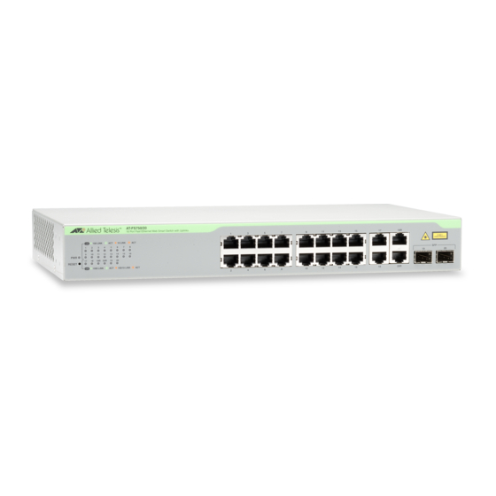
Chapter 1: Overview Switch Front Panels This section shows the design of the front panel for each model. AT-FS750/20 Figure 1 illustrates the front panel of the AT-FS750/20 switch. Model 10/100Base-T SFP Slots Port LEDs 10/100/1000Base-T Twisted-Pair Ports Twisted-Pair Ports Figure 1. -
Page 15: At-Fs750/52 Model
FS750 Series Fast Ethernet Switches Installation Guide AT-FS750/52 Figure 4 illustrates the front panel of the AT-FS750/52 switch. Model Port LEDs AT-GS924M 10/100/1000Base-T 10/100Base-T SFP Slots Twisted-Pair Ports Twisted-Pair Ports Figure 4. AT-FS750/52 Switch Front Panel... -
Page 16: Management Software
Chapter 1: Overview Management Software The FS750 Series Fast Ethernet switches are shipped with the WebSmart management software pre-installed. The software provides a web-browser interface for in-band, over-the-network management. In the unlikely event that the management software becomes corrupted or damaged on the switch, you can download the software from the Allied Telesis corporate web site and reinstall it on the switch. -
Page 17: Twisted-Pair Ports
FS750 Series Fast Ethernet Switches Installation Guide Twisted-Pair Ports The AT-FS750/20, AT-FS750/28, AT-FS750/28PS, and AT-FS750/52 Fast Ethernet Switches feature 16, 24, 24, and 48 twisted-pair ports, respectively. These ports are 10Base-T and 100Base-TX compliant. You can set the port speeds and duplex modes either automatically with IEEE 802.3u Auto-Negotiation or manually with the WebSmart management... -
Page 18: Combo Ports
Chapter 1: Overview Combo Ports The FS750 Series Fast Ethernet switches have two pairs of combo ports. Each combo port consists of one 10/100/1000Base-T twisted-pair port and one slot for an optional 100Base-FX or 1000Base-SX/LX SFP transceiver. The twisted-pair ports are identified with the letter “R” for “Redundant” on the front face plates of the units. -
Page 19: Leds
FS750 Series Fast Ethernet Switches Installation Guide LEDs The FS750 Series Fast Ethernet switcheses are equipped with LEDs to indicate the switch status. Power LED Table 2 describes the power LED. Table 2. Power LED State Description The switch is not receiving power. -
Page 20: Sfp Leds
Chapter 1: Overview Table 4. 10/100/1000Base-T Port LEDs State Description The port has not established a link with a network device. Blinking The port is transmitting or receiving network Green packets and operating at 1000 Mbps. Steady The port has established a link to a network Green device and can operate at 1000 Mbps. -
Page 21: Poe Max Led (At-Fs750/28Ps)
FS750 Series Fast Ethernet Switches Installation Guide POE MAX LED Table 7 describes the POE MAX LED. This LED is available only for the AT-FS750/28PS switch. (AT-FS750/28PS) Table 7. POE MAX LED State Description POE MAX The switch has spare power for a new PD. -
Page 22: Reset Button
Chapter 1: Overview Reset Button To reset your switch, press the RESET button on the front panel. Pressing the reset button initiates a system reboot of the switch and reloads the current configuration file. Caution The switch does not forward network traffic during the reset process. ... -
Page 23: Power Supply
FS750 Series Fast Ethernet Switches Installation Guide Power Supply Each switch has an internal power supply with a single AC power supply socket on the back panel. To power the switch on or off, connect or disconnect the power cord provided with the switch. A power cord is supplied with the switch. - Page 24 Chapter 1: Overview...
-
Page 25: Chapter 2: Installation
Chapter 2 Installation This chapter contains the following sections: “Reviewing Safety Precautions” on page 26 “Selecting a Site for the Switch” on page 30 “Cable Specifications” on page 31 “Unpacking the Switch” on page 32 “Installing the Switch on a Desktop or Table” on page 33 ... -
Page 26: Reviewing Safety Precautions
Note Important: The indicates that translations of the safety statement are available in the PDF document “Translated Safety Statements” posted on the Allied Telesis website at alliedtelesis.com/support. Warning Class 1 Laser product. Warning Do not stare into the laser beam. - Page 27 FS750 Series Fast Ethernet Switches Installation Guide Warning Power cord is used as a disconnection device. To de-energize equipment, disconnect the power cord. Warning Class I Equipment. This equipment must be earthed. The power plug must be connected to a properly wired earth ground socket outlet.
- Page 28 Chapter 2: Installation Note If installed in a closed or multi-unit rack assembly, the operating ambient temperature of the rack environment may be greater than the room ambient temperature. Therefore, consideration should be given to installing the equipment in an environment compatible with the manufacturer’s maximum rated ambient temperature (Tmra).
- Page 29 FS750 Series Fast Ethernet Switches Installation Guide Caution The switch does not forward network traffic during the reset process. ...
-
Page 30: Selecting A Site For The Switch
Chapter 2: Installation Selecting a Site for the Switch Observe the following requirements when choosing a site for your switch: If you plan to install the switch in an equipment rack, verify that the rack is safely secured and will not tip over. Devices in a rack should be installed starting at the bottom, with the heavier devices near the bottom of the rack. -
Page 31: Cable Specifications
FS750 Series Fast Ethernet Switches Installation Guide Cable Specifications Table 9 contains the cable specifications for the twisted-pair ports. Table 9. Twisted-Pair Cabling and Distances Maximum Speed Type of Cable Operating Distance 10 Mbps Standard TIA/EIA 568-B-compliant 100 m (328 ft) -
Page 32: Unpacking The Switch
Chapter 2: Installation Unpacking the Switch To unpack the switch, perform the following procedure: 1. Remove all of the components from the shipping package. Note Store the packaging material in a safe location. You must use the original shipping material if you need to return the unit to Allied Telesis. -
Page 33: Installing The Switch On A Desktop Or Table
FS750 Series Fast Ethernet Switches Installation Guide Installing the Switch on a Desktop or Table You may install the switches on a desktop or table, or in a standard 19-inch equipment rack. To install the switch in a rack, see “Installing the Switch in an Equipment Rack”... -
Page 34: Installing The Switch In An Equipment Rack
Chapter 2: Installation Installing the Switch in an Equipment Rack To install the switch in a standard 19-inch equipment rack, perform the following procedure: 1. If the rubber feet are attached to the bottom of the switch, remove them using a flat-head screwdriver. 2. - Page 35 FS750 Series Fast Ethernet Switches Installation Guide 3. Mount the switch in a standard 19-inch equipment rack using four equipment rack screws (not provided with the switch) as shown in Figure 7. Figure 7. Mounting the Switch in an Equipment Rack 4.
-
Page 36: Installing The Switch On A Wall
Chapter 2: Installation Installing the Switch on a Wall To install the switch on a wall, perform the following procedure: 1. Turn the switch over and place it on a table. 2. If the rubber feet are attached to the bottom of the switch, remove them using a flat-head screwdriver. - Page 37 FS750 Series Fast Ethernet Switches Installation Guide 5. Install the four plastic anchors included with the switch into the wall, at the locations marked in the previous step. The anchors require 0.635 mm (0.25 in.) holes. 6. While another person holds the switch at the wall location, secure it to the wall using the four wall mounting screws.
-
Page 38: Installing Sfp Transceivers
Chapter 2: Installation Installing SFP Transceivers To install an SFP transceiver, perform the following procedure: Note The transceiver can be hot-swapped; you do not need to power off the switch to install a transceiver. However, you should always remove the cables before removing the transceiver. Note You should always install the transceiver before connecting the fiber-optic cables to it. - Page 39 FS750 Series Fast Ethernet Switches Installation Guide 4. Verify that the handle on the transceiver is in the upright position, as shown in Figure 12. This secures the transceiver and prevents it from being dislodged from the slot. SFP Transceiver...
-
Page 40: Cabling The Switch
Chapter 2: Installation Cabling the Switch Observe the following guidelines when connecting twisted-pair and fiber-optic cables to the ports on the switch: The connector on the cable should fit snugly into the port on the switch. The tab on the connector should lock the connector into place. -
Page 41: Powering On The Switch
4. If your switch is an AT-FS750/28PS model, verify the SYS LED is green. The switch is now powered on and ready for network operations. For information on how to manage the switch, see the FS750 Series Web Management User’s Guide. - Page 42 Chapter 2: Installation...
-
Page 43: Chapter 3: Troubleshooting
This chapter contains information on how to troubleshoot the switch if a problem occurs. Note For further assistance, please contact Allied Telesis Technical Support at alliedtelesis.com/support. Problem 1: The POWER LED on the front of the switch is off. Solutions: The unit is not receiving power. Try the following: Verify that the power cord is securely connected to the power ... - Page 44 Chapter 3: Troubleshooting Verify that you are using the appropriate category of twisted-pair cable: Category 3 or better for 10 Mbps operation and Category 5 and Category 5E for 100 Mbps operation. Problem 3: The Link Activity LED for an SFP transceiver is off. Solutions: The fiber-optic port on the transceiver is unable to establish a link to a network device.
-
Page 45: Appendix A: Technical Specifications
Appendix A Technical Specifications This appendix contains the following specifications: “Physical Specifications” “Environmental Specifications” on page 46 “Power Specifications” on page 46 “Safety and Electromagnetic Emissions Certifications” on page 46 “Connectors and Port Pinouts” on page 48 ... -
Page 46: Environmental Specifications
Appendix A: Technical Specifications Environmental Specifications Table 13 shows the environmental specifications. Table 13. Environmental Specifications Operating Temperature 0° C to 40° C (32° F to 104° F) Storage Temperature -20° C to 70° C (-4° F to 158° F) Operating Humidity 5% to 90% non-condensing Storage Humidity... - Page 47 FS750 Series Fast Ethernet Switches Installation Guide...
-
Page 48: Connectors And Port Pinouts
Appendix A: Technical Specifications Connectors and Port Pinouts This section lists the connectors and connector pinouts. Figure 14 illustrates the pin layout for an RJ-45 connector and port. Figure 14. RJ-45 Connector and Port Pin Layout Table 16 lists the RJ-45 pin signals when a twisted-pair port is operating in the MDI configuration. - Page 49 FS750 Series Fast Ethernet Switches Installation Guide Table 18 lists the RJ-45 connector pins and their signals when a 1000Base-T port is operating at 1000 Mbps. Table 18. RJ-45 1000Base-T Connector Pinouts Pair Signal TX and RX+ TX and RX-...
- Page 50 Appendix A: Technical Specifications...