
Subscribe to Our Youtube Channel
Related Manuals for Jetter JetMove D203


Summary of Contents for Jetter JetMove D203
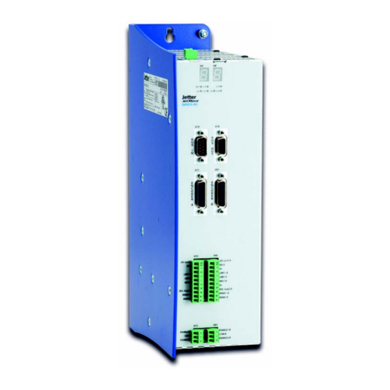
- Page 1 User Manual JM-D203-230 - Digital Servoamplifier 60870727 We automate your success.
- Page 2 April 2020 / Printed in Germany Translation of the original German language document. Jetter AG reserves the right to make alterations to its products in the interest of technical progress. These alterations need not be documented in every single case.
- Page 3 E-Mail - Sales: sales@jetter.de E-Mail - Technical Hotline: hotline@jetter.de Internet Address: http://www.jetter.de This Operator's Manual is an Integral Part of the JetMove D203: Type: Serial #: Year of construction: Order #: To be entered by the customer: Inventory #: Place of operation:...
- Page 4 Therefore, keep in a way that it is always at hand until the the digital servo amplifier JetMove D203 will be disposed of. • Pass this manual on if the digital servo amplifier JetMove D203 is sold or loaned/ leased out. In any case you encounter difficulties to clearly understand this user manual, please contact the manufacturer.
- Page 5 JetMove D203 Introduction Description of Symbols This sign is to indicate a possible impending danger of serious physical damage or death. DANGER This sign is to indicate a possible impending danger of light physical damage. This sign is also to warn you of material damage.
- Page 6 Automatically running processes or results to be achieved are marked by this arrow. PC and user interface keys. This symbol informs you of additional references (data sheets, literature, etc.) associated with the given subject, product, etc. It also helps you to find your way around this manual. Jetter AG...
-
Page 7: Table Of Contents
Table of Contents Safety Instructions General Safety Instructions Ensure your own safety Residual Dangers Instructions on EMC Installation of the JetMove D203 Scope of Delivery Mechanical Installation Electrical Installation Checking the Installation Notes on Safety as regards the Installation Safety Instructions for Commissioning... - Page 8 12.3.4 Numbering system of digital inputs located on expansion modules 12.4 Digital Outputs 12.4.1 Technical data 12.4.2 Description of the LEDs 12.4.3 Description of connections 12.4.4 Numbering system of digital inputs located on expansion modules 12.5 Serial Interfaces 12.6 Ethernet Interface Jetter AG...
- Page 9 JetMove D203 Table of Contents 12.6.1 Connecting to the RJ45 jack 12.6.2 Connection between -JC24X and PC 12.6.3 Connection between -JC24X, switch, and PC 12.6.4 Connection via several switches 12.7 Status LEDs, Mode Selector 12.7.1 LEDs 12.7.2 The mode selector 12.8...
- Page 10 Table of Contents Jetter AG...
- Page 11 Chapter 5 "Technical Da- ta", page 37. Do not apply a voltage to the digital servo amplifier JetMove D203 that is higher than the specified operating voltage. The operating voltage voltage of the JM-D203 is 195 ... 265 VAC (one-phase). Thus, the digital servo amplifier is subject to the EU Low Voltage Directive.
- Page 12 The installation of such parts may impair the safety and the proper functioning of the digital servo amplifier JetMove D203. Any liability on the part of Jetter AG for any damages resulting from the use of non- original parts and equipment is excluded.
- Page 13 1.1 General Safety Instructions 1.1.5 Repairs and Maintenance Repairs to the digital servo amplifier JetMove D203 must not be carried out by the operator. The servo amplifier JetMove D203 does not contain any parts which can be repaired by the operator.
- Page 14 PCBs) are connected by screw connections. To disassemble the servo amplifier just remove the screws. Ensure your own Safety Isolate the JetMove D203 from the mains if maintenance works have to be carried out. By doing so, you will prevent accidents resulting from electric voltage and moving parts.
- Page 15 Replace damaged or unreadable information signs and labels. 1.2.3 Earthing Procedure Screw the enclosure of the JetMove D203 down to a highly conductive, plane and earthed panel. Use the JetMove D203 only in earthed industrial networks with one mains phase and neutral conductor (TN network, TT network with earthed neutral point, max.
- Page 16 If this advice is disregarded and an RCD is installed, it will switch off the servo amplifier although there is no error. When an earth-leakage current breaker needs to be installed, an isolating trans- former must be used. Jetter AG...
- Page 17 During operation, keep all covers and electric cabinet doors closed. Do not remove the cover. Do not disconnect electrical connections of the JetMove D203 while they are energized. Do not touch the terminals X1, X74 and X84 while the servo amplifier is running.
- Page 18 DANGER Danger of injuries caused by mechanic force! The JetMove D203 has been designed for driving a motor. This motor moves mechanic parts or sharp edges. Therefore, failure or malfunctioning of the Jet- Move D203 can be dangerous for persons or damage the machinery. This should be prevented by installing additional safety devices.
- Page 19 JetMove D203 1.3 Residual Dangers 1.3.2 Hazards after POWER is turned OFF Danger resulting from electric shock! Capacitors of the servo amplifier can store dangerous voltages up to 5 minutes after switching off the operating voltage. Wait always at least 5 minutes after switching off, before touching live DANGER parts or disconnecting terminal leads.
- Page 20 1 Safety instructions Instructions on EMC The digital servo amplifier JetMove D203 is intended for use in industrial environ- ment. It may cause radio interferences when used in residential areas. It is operated at the operator's own risk. The noise immunity of a system is determined by the weakest component of the sys- tem.
- Page 21 JetMove D203 1.4 Instructions on EMC Connect the shields at both ends of the cables. Unshielded wire ends of shielded cables should be as short as possible. Draw the entire shield behind the isolation, and then clamp it under an earthed strain relief with the greatest possible surface area.
-
Page 22: Jetmove D203
1 Safety instructions JetMove D203 Mating Connector Cable Strap Motor Cable Abb. 3: Shielding of screw terminals to EMC standards Jetter AG... -
Page 23: Installation Of The Jetmove D203
JetMove D203 2.1 Scope of Delivery Installation of the JetMove D203 Scope of Delivery • Digital servo amplifier JetMove D203 • Mating connector plugged-on • Cable straps serving as strain relief and motor cable shield • User Manual Accessories Accessories are not part of the scope of delivery! •... -
Page 24: Mechanical Installation
Please check the shipment for completeness. To ensure proper functioning of the JetMove D203, check whether the mounting plate in the electric cabinet is unpainted. The only possible mounting position is vertical - see fig. 4, page 25. - Page 25 JetMove D203 2.2 Mechanical Installation All measurements in mm r=2.8 r=4.8 r=2.8 Fig. 4: Rear/front view of the JetMove D203 enclosure with mounting holes Jetter AG...
-
Page 26: Electrical Installation
Verify that all earthing cables are connected (double earthing). To connect resolvers or power units you can use prefabricated cables available from Jetter or opt for self-made cables. Please refer to chapter 7 "Description of Connections", page 49. To ensure that installation is carried out in conformance with EMC regulations, follow the instructions below: –... -
Page 27: Checking The Installation
Please take into account the information on residual dangers given in chapter 1.3.2 "Hazards after POWER is turned OFF", page 19. Before carrying out installation and maintenance jobs, separate the servo amplifier JetMove D203 and all connected devices from the mains. Jetter AG... -
Page 28: Safety Instructions For Commissioning
Only connect position encoders to the servo amplifier if they are sufficiently isolated from the connected mains and motor circuits. The digital servo amplifier JetMove D203 has got a leakage current greater than 3.5 mA. In order to avoid electric shocks, a second protective earth conductor will be required. -
Page 29: Operating Conditions
JetMove D203 Operating Conditions Danger in the event that the operating parameters for the "Safe Torque Off" option of the JM-D203-...-S1 amplifiers are not complied with. Dangerous injuries can occur! DANGER For example from • electric shock because the electrical safety has been violated by not complying with the degree of pollution;... - Page 30 Operating altitude 1,000 m max. above sea level DIN EN 50178 without derating. From 1,000 to 2,000 m above sea level; derating 1.5 % per 100 m increase in alitude Jetter AG...
- Page 31 JetMove D203 Operating Parameters Mechanical Parameters Parameter(s) Value(s) Reference standard Free falls Within original packing, the device DIN EN 50178 withstanding test withstands dropping over all of its DIN EN 60068-2-31 edges Vibration resistance • 10 Hz ... 57 Hz : 0.075 mm...
- Page 32 Follow the instructions below: If this product is used in a residential environment, take appropriate measures. One of the measures is to use additional line filters. See "Line filter" on page 39. Jetter AG...
- Page 33 JetMove D203 Operating Parameters EMI - Immunity to Interference Enclosure Parameter(s) Value(s) Reference standard Discharge through air: DIN EN 61800-3 Test peak voltage 8 kV DIN EN 61000-4-2 Contact discharge: Test peak voltage 4 kV Criterion B (Electromagnetic environment in...
- Page 34 Criterion B (Electromag. envir. in ind. plants) Guided radio Frequency 0.15 ... 80 MHz DIN EN 61800-3 disturbances Test voltage 10 V DIN EN 61000-4-6 AM 80 % at 1 kHz Criterion A (Electromag. envir. in ind. plants) Jetter AG...
-
Page 35: Physical Dimensions
JetMove D203 Physical Dimensions All measurements in mm Fig. 5: Physical dimensions of the JetMove D203 For installation, please also refer to fig. 4 on page 25. Jetter AG... - Page 36 4 Physical Dimensions Jetter AG...
-
Page 37: Technical Data
JetMove D203 5.1 Electrical Specification Technical Data Electrical Specification Danger in the event that the Electrical Specification for the "Safe Torque Off (STO)" option of the JM-2xx-xxx...-S1 amplifiers is not complied with. Serious injuries can occur! For example from •... - Page 38 NRTL listed (acc. To UL 508)(NKJH) ) self protected combination motor controller (specification: 10 A). The JetMove D203 is suitable for use on a circuit capable of delivering not more than 5000 (rms) symmetrical Amperes, 230 Volts maximum.
- Page 39 JetMove D203 5.1 Electrical Specification Electrical Specification Line filter A line filter ensuring unlimited EMC in residential environment to DIN EN 61800-3 is needed. The following filters can be applied with input circuits: – NEFB 10332 with I = 16 A –...
- Page 40 • 1 differential channel per axis • Resolution 12 bits • Voltage range 0 ... 10 V • Value range 0 ... 32767 (in steps of 8) • Sampling interval 2 ms Ω • Input impedance 200 k Jetter AG...
- Page 41 The duration for the peak current is measured at a starting temperature of 45 °C at the heat sink. INFO 2 A line filter can supply several digital servo amplifiers JetMove D203, if I (the rated current of the line filter) is greater than the total current of the connected servo amplifiers.
- Page 42 – At the bolt on the top side of the enclosure by a minimum cross-sectional area of 10 mm² WARNING – in two positions, namely at the bolt on the top side of the enclosure, and at the PE terminal X1; for this, see chapter 1.2.3 "Earthing Procedure", page 15. Jetter AG...
-
Page 43: Motor Protection
Jetter AG. Motor Protection There are three ways of motor protection: 5.2.1 Thermal sensor integrated in the motor The servo amplifier JetMove D203 can read out and process four different motor temperature sensors: Sensor type Type of sensor signal evaluation Temperature... -
Page 44: I²T Calculation
It is possible to parameterize the warning level. The error level (error 30) is set to 100 %. The I²t value is readable in a variable of JetMove D203 through JetSym or the PLC. The digital servo amplifier JetMove D203 calculates the percentage of motor power loss according to the following formula: ... -
Page 45: Motor Overload Calculation To Ul
Because of the fact that after reset the motor overload calculation always starts at zero, the result is wrong if the motor is already hot when the JetMove D203 is energized (that is, when the 24 V logic power supply is applied). - Page 46 5 Technical Data Jetter AG...
-
Page 47: Drive Controller Structure
JetMove D203 Drive Controller Structure Fig. 7: Block diagram of drive controller structure All drive controllers can be parameterized through the control program. Jetter AG... - Page 48 – Resolution of velocity pickup 20 bits per revolution – Sampling interval 62.5 µs Sine-cosine sensor: – Resolution of absolute position 15 bits per encoder period – Resolution of velocity pickup 20 bits per encoder period – Sampling interval 62.5 µs Jetter AG...
-
Page 49: Description Of Connections
JetMove D203 7.1 Mains Power Supply Description of Connections • For axis A, the connection designations X71 through X74 are available. • For axis B, the connection designations X81 through X84 are available. Mains Power Supply Specification of terminal X1 •... -
Page 50: Motor Connection
Cable shielding • Braided copper shield of 80 % coverage min. Connection of the motor to the digital servo amplifier JetMove D203 has to be done following the wiring diagram below. Connection of the brake is optional. internal circuit X72/X82... -
Page 51: General Information
JetMove D203 7.2 Motor Connection 7.2.2 General Information NOTICE Alternative measures to avoid malfunctions of the control system and the motor: Operate the brake through a separately shielded brake line. Always connect brake lines to a separate power supply unit DC 24 V if brake and motor lines are run together in one bunch of cables, and are not separately shielded. -
Page 52: Motor Cables With Sc Mating Connector
The ready-made motor power cable with SC mating connector can be ordered from Jetter AG. It is equipped with the corresponding motor mating connector and can be ordered from Jetter AG by specifying the following cable confection number (KABEL-KONF): Without brake: Cable confection # 26.1... - Page 53 JetMove D203 7.2 Motor Connection Cable Specification of the Motor Power Cable with Mating Connector SC for JetMove D203 For connection without motor holding brake Motor Power Cable - Cable Confection # 26.1 Wiring Terminals Shield Mating JetMove D203 Connector of the...
- Page 54 7 Description of Connections For connection with motor holding brake Motor Power Cable - Cable Confection # 24.1 Wiring Terminals Shield Mating JetMove D203 Connector of the Motor (female, solder side) 4 x 1.5 mm Highly flexible (2 x 1.5 mm...
-
Page 55: Connection Assignment Of Terminal Box
JetMove D203 7.2 Motor Connection 7.2.4 Connection assignment of terminal box Connection Assignment of Terminal Box Connection Motor Terminal Box - Terminal Assignment Terminals of the Amplifier X74 / X84.U2 Pin 1 Phase 1 X74 / X84.V2 Pin 2 Phase 2 X74 / X84.W2... -
Page 56: Resolver Connection
Article # 15100069 Resolver / HIPERFACE The complete resolver cable connecting the servo amplifier series JetMove D203 and synchronous servo motors can be ordered from Jetter AG by specifying the following item number (KAY) and the respective cable length in cm: KAY_0823-xxxx... - Page 57 JetMove D203 7.3 Resolver Connection Resolver Cable - KAY_0823-xxxx JetMove D203 Shield Motor (Resolver) (SUB-D connector (female, solder X71 / X81) side) Solder Side Shield Cable Adapter Counter Plug Union nut Seal and pull relief element Shield Case 360° round...
- Page 58 0 V. A coded encoder connector can be checked via the application program of the controller. Mating connector of the resolver (solder side) Solder Side 10 2 Fig. 11: RC series mating connector of the resolver (internal thread M23) Jetter AG...
-
Page 59: Hiperface Connection
Jetter AG by specifying item number 15100069. The complete resolver cable connecting the servo amplifier series JetMove D203 and synchronous servo motors can be ordered from Jetter AG by specifying the following item number (KAY) and the respective cable length in cm:... - Page 60 7 Description of Connections HIPERFACE Cable - KAY_0923-xxxx JetMove D203 Shield Motor (SUB-D connector (HIPERFACE) X71 / X81) (female, solder side) Solder Side Cable Shield Adapter Counter Plug Union nut Seal and pull relief element Shield Case 360° round connection of...
- Page 61 JetMove D203 7.4 HIPERFACE Connection Dimensions of the HIPERFACE mating connector are specified in millimeters. INFO 1 Supply voltage: With the help of the sense resistor, the supply voltage can be set for the encoder. The resistance can be calculated by the following formula: 4700Ω...
-
Page 62: Sin-Cos Encoder Connection
0 V and voltage supply • The shield must be connected to the connector housings on both ends of the cable with the greatest possible surface area. • Material: Copper • Temperature class: 60 °C • Maximum cable length: 100 m Jetter AG... - Page 63 JetMove D203 7.5 Sin-Cos Encoder Connection Sin-Cos Encoder Cable JetMove D203 Shield Cable Specification (SUB-D Connector X71 / X81) Maximum cable length: 100 m Shield Attaching screws must Connect shield with the have a metric thread! greatest possible surface area!
- Page 64 Supply voltage +5 V at the JetMove D203: If the sense wires are not connected, the supply voltage of +5 V is issued at the JetMove D203. Due to performance degradation, a lower voltage might be supplied to the encoder.
- Page 65 7.5 Sin-Cos Encoder Connection INFO 1.3 Supply voltage +5 ... 8.5 V at the JetMove D203: With the help of the sense resistor, the supply voltage can be set for the encoder. The resistance can be calculated by the following formula: 4700Ω...
-
Page 66: Incremental Encoder Connection
0 V and voltage supply • The shield must be connected to the connector housings on both ends of the cable with the greatest possible surface area. • Material: Copper • Temperature class: 60 °C • Maximum cable length: 100 m Jetter AG... - Page 67 JetMove D203 7.6 Incremental Encoder Connection Incremental Encoder Cable JetMove D203 (SUB-D Shield Specifications Connector X71 / X81) of the Cable Encoder signal: 5 V difference signal Shield Maximum cable length: 100 m Attaching screws must Connect shield with the...
- Page 68 Supply voltage +5 V at the JetMove D203: If the sense wires are not connected, the supply voltage of +5 V is issued at the JetMove D203. Due to performance degradation, a lower voltage might be supplied to the encoder.
- Page 69 JetMove D203 7.6 Incremental Encoder Connection INFO 2 Selecting signal: By means of the selecting signal, a coding can be carried out, in order to diagnose mixing up the two encoder connectors. This is only useful, if one of the two encoder connectors has got this coding.
-
Page 70: Digital Inputs, Logic Power Supply
DC 24 V switch parameter setting, this • 7.5 mA max. (Input) input is used for • Operating point: reference run < 6 V low, > 15 V high NC or NO contact Common Ground for all inputs ground Jetter AG... - Page 71 JetMove D203 7.7 Digital Inputs, Logic Power Supply Digital Inputs, Brake Terminals Terminals Signal Description Specification X72/X82 LIMIT + Positive • Depending on the • DC 24 V limit switch parameter setting, this • 7.5 mA max. (input) input is used as a •...
- Page 72 BRAKE - closes the contact D203 at release of the BRAKE- by internal motor current. ground. JetMove D203 is equipped with an internal freewheeling diode. Contact: Type NO These connections are only for devices having got the same reference to ground as the power supply of the logic.
-
Page 73: Enable Input Without Option -S1
JetMove D203 7.7 Digital Inputs, Logic Power Supply 7.7.1 Enable Input without Option -S1 (Safe Torque Off) Specification of terminal X73 / X83 • 2-pin screw clamping terminal (type MC 1.5/ 2-ST-3.81) • Cross-sectional area of connecting cable: 0.14 ... 1.5 mm (AWG 26 - AWG 16) with bootlace ferrules in a plastic sleeve: 0.25 ... -
Page 74: Enable Input With Option -S1
• A low signal de- energizes the motor after 1 ms (OSSD filtering). Please refer to chapter 11 "Option -S1: STO", page 91 Connections see “Connection Diagrams”, page 87. JX2 System Bus Jetter AG... -
Page 75: Specification Of The Jx2 System Bus Cable
JetMove D203 7.8 JX2 System Bus The JetMove D203 is interlinked with the controller, other JetMove amplifiers, or JX2 peripheral modules by means of the JX2 system bus. The JX2 system bus input BUS-IN is a 9-pin male Sub-D connector, and the JX2 bus output BUS-OUT is a 9-pin female Sub-D connector. - Page 76 125 kBaud 200 m JX2 System Bus Cable - Cable Confection # 530 Shield Shield Shield BUS-OUT Connect shield with the greatest BUS-IN possible surface area! Use metallized housing only! Signal CMODE0 CMODE1 TERM Vacant Vacant Do not connect Jetter AG...
-
Page 77: Analog Input
JetMove D203 7.9 Analog Input Analog Input 7.9.1 Function Both the male connector X18 and the female connector X19 let you connect analog inputs. These analog inputs have got a resolution of 12 bit. The converted value of the measured voltage can be read from a register of the JetMove by the application program or processed by the firmware of the JetMove in an additional controller. - Page 78 Pin Assignment - Analog Input Connector for Axis B Shield Shield Connect shield with the greatest possible surface area! Use metallized housing only! Signal Analog signal (0 - 10 V to pin 8) Reference of the analog signal (not connected with 0 V of the controller) Jetter AG...
-
Page 79: Status Monitoring
Notice! The 7-segment display of the output stage indicates the operating and fault conditions of the digital servo amplifier JetMove D203. The various display modes are set by the Motion Setup. Mode 0 (default) is used for normal operation and mode 1 for commissioning. - Page 80 8 Status Monitoring JetMove D203 - Seven-Segment Display Mode 0: Normal Operation Display Status Description QUICK STOP A quick stop has been activated. ACTIVATED The drive is being decelerated to n = 0 and then locked. ERROR REACTION A fault has been recognized.
-
Page 81: Diagnostics
Diagnostics Error Messages INFO In the case of a error message, the letter "F" and two successive numbers appear on the 7-segment display every second. Fault Message Table for the JetMove D203 Error Number Type of Error Description Response to... - Page 82 9 Diagnostics Fault Message Table for the JetMove D203 Error Number Type of Error Description Response to Troubleshooting Errors F 05 Current The output current – Immediate – Check cable and overload has been greater locking of motor for a short than 2.5 x the...
- Page 83 JetMove D203 9.1 Error Messages Fault Message Table for the JetMove D203 Error Number Type of Error Description Response to Troubleshooting Errors F 13 (combined Internal An internal – Immediate – Switch the 24 V with F00) checksum error checksum error...
- Page 84 9 Diagnostics Fault Message Table for the JetMove D203 Error Number Type of Error Description Response to Troubleshooting Errors F 20 Undervoltage The DC link – Stop with – Check the voltage of DC link voltage voltage is less emergency...
- Page 85 JetMove D203 9.1 Error Messages Fault Message Table for the JetMove D203 Error Number Type of Error Description Response to Troubleshooting Errors I²t Error The average – Immediate – Let the motor cool power loss of the locking of down...
-
Page 86: Warnings
9 Diagnostics Fault Message Table for the JetMove D203 Error Number Type of Error Description Response to Troubleshooting Errors F 42 Malfunction of Broken encoder – Immediate – Check the encoder encoder 2 (only line or initialization motor power line and all plug-in... -
Page 87: Connection Diagrams
JetMove D203 Connection Diagrams 24 V Bus cable connection Bus cable connection to with upstream device downstream device JetMove D203 Motor B Motor A AC 230 V L1’ L2' Filter 24 V Contactor Fig. 19: Connection diagram JM-D203, type of position transducer: Resolver... - Page 88 Bus cable connection Bus cable connection with the upstream device with the downstream device JetMove D203 Motor B Motor A AC 230 V L1’ L2' Filter 24 V Contactor Fig. 20: Connection diagram JM-D203, type of position transducer: HIPERFACE Jetter AG...
- Page 89 Bus cable connection Bus cable connection with upstream device with downstream device JetMove D203 Motor B Motor A AC 230 V L1’ L2' Filter 24 V Contactor Fig. 21: Connection diagram JetMove D203, of the following option: S1 Jetter AG...
- Page 90 Position transducer (resolver or HIPERFACE encoder) Motor-temperature protection (see “Thermal sensor integrated in the motor" on page 43) At using the option -JC24x, the Bus-In connector X18 must not be applied, as the system bus is connected with the JM-D203 internally. Jetter AG...
-
Page 91: Option -S1: Sto
2xx.html jm-2xx_sto-option_fb_xxx_function_description Functional description with safety instructions to be observed and measures concerning "STO". Item # 60878628 INFO At Jetter AG, the safety function "STO" is referred to as "Safe Standstill" in the order list for example. Jetter AG... - Page 92 11 Option -S1: STO Jetter AG...
-
Page 93: Option -Jc24X
-JC24X. You can use our prefabricated programming, HMI and connecting cables for the Jetter system bus. For more information refer to chapter 12.10.1 "Overview of interface cables", page 119. For installation according to EMC, the chapter 1.4 "Instructions on EMC", page 20 must be read and followed. -
Page 94: Power Supply
INFO Protection against polarity reversal: The -JC24X is protected against reverse polarity. As a test, a voltage of 24 volt with reversed polarity was applied to the test object for 10 s. Jetter AG... -
Page 95: Description Of Connections
JetMove D203-JC24X 12.2 Power Supply 12.2.2 Description of connections Terminal Specifications • 2-pin plug-in screw terminal COMBICON RM 3.5 (for printed-circuit boards) (AWG 24 ... AWG 14) • Allowed conductor size: 0.25 ... 2.5 mm (AWG 24 ... AWG 14) with bootlace ferrules in a plastic sleeve: 0.14 ... -
Page 96: Digital Inputs
5 V max. Signal processing Dynamic Electrical isolation Electrical isolation to logic is available All digital inputs and outputs have got the same reference potential. A digital output may directly (without additional load) be connected to a digital input. INFO Jetter AG... -
Page 97: Description Of The Leds
JetMove D203-JC24X 12.3 Digital Inputs 12.3.2 Description of the LEDs Fig. 23: LEDs of the digital inputs of the -JC24X LEDs of Digital Inputs Designation Color Description IN 1 ... 16 yellow Digital input 1 through 16 Signal voltage ON... -
Page 98: Description Of Connections
Digital input # 8 X21.7 Digital input # 7 X21.6 Digital input # 6 X21.5 Digital input # 5 X21.4 Digital input # 4 X21.3 Digital input # 3 X21.2 Digital input # 2 X21.1 Digital input # 1 Jetter AG... -
Page 99: Numbering System Of Digital Inputs Located On Expansion Modules
JetMove D203-JC24X 12.3 Digital Inputs The connection of the digital inputs of the -JC24X is shown in Fig. 24. Voltage Supply +24 V Fig. 24: External circuit of the digital inputs 4 and 13 12.3.4 Numbering system of digital inputs... -
Page 100: Digital Outputs
Principle of operation Non-latching Signal voltage ON Typ. V -1.5 V supply All digital inputs and outputs have got the same reference potential. A digital output may directly (without additional load) be connected to a digital input. INFO Jetter AG... -
Page 101: Description Of The Leds
JetMove D203-JC24X 12.4 Digital Outputs 12.4.2 Description of the LEDs Fig. 25: LEDs of the digital outputs of the -JC24X LEDs of Digital Outputs Designation Color Description OUT 1 ... 12 Yellow Digital output 1 through 8 Signal voltage ON... -
Page 102: Description Of Connections
Digital output # 8 X31.7 Digital output # 7 X31.6 Digital output # 6 X31.5 Digital output # 5 X31.4 Digital output # 4 X31.3 Digital output # 3 X31.2 Digital output # 2 X31.1 Digital output # 1 Jetter AG... -
Page 103: Numbering System Of Digital Inputs Located On Expansion Modules
JetMove D203-JC24X 12.4 Digital Outputs Fig. 26 shows the connection details of the digital outputs of the -JC24X. Voltage Supply +24 V Load Load Fig. 26: External circuit of the digital outputs 3 and 5 12.4.4 Numbering system of digital inputs... -
Page 104: Serial Interfaces
DC 24 V Power supply of the HMI (Ser2 only) RS-422 (Ser2 only) RS-232 RS-422 Ser2 (8-Pin MiniDIN Jack) Ser1 or Ser2 Jack Signal Comment RS-422 Ground RS-422 RS-232 RS-422 DC 24 V Supply of the HMI RS-422 RS-232 Jetter AG... -
Page 105: Ethernet Interface
JetMove D203-JC24X 12.6 Ethernet Interface 12.6 Ethernet Interface 12.6.1 Connecting to the RJ45 jack The integrated controller -JC24X is connected to the Ethernet through its RJ45 jack. There are two types of interconnecting cables used for 10/100 MBit/s twisted pair Ethernet. -
Page 106: Connection Between -Jc24X And Pc
Fig. 28: Ethernet connection between PC and JetControl 12.6.3 Connection between -JC24X, switch, and If connection between a PC and -JC24X is established through a switch, straight- through cables have to be used. JetMove-D203-JC24X Switch JetMove-D203-JC24X Fig. 29: Ethernet connection between -JC24X and switch Jetter AG... -
Page 107: Connection Via Several Switches
JetMove D203-JC24X 12.6 Ethernet Interface 12.6.4 Connection via several switches The switches have to be interconnected by means of crossover cables. The connections between -JC24X and switch, as well as between PC and switch, have to be made by means of straight-through cables. - Page 108 INFO If the proper cable is not available, the uplink port of a switch/hub can be used. Some devices are provided with an automatic crossover function which ensures automatic adjustment to the cable and distant station. Jetter AG...
-
Page 109: Status Leds, Mode Selector
JetMove D203-JC24X 12.7 Status LEDs, Mode Selector 12.7 Status LEDs, Mode Selector 12.7.1 LEDs Fig. 31: Status LEDs Status LEDs Vout (green) Supply voltage for the digital output driver is OK ERR2 (red) Error in the output driver Overload, short circuit,... - Page 110 Serious OS error LED (RUN) are flashing alternately during runtime. The red LED (ERR1) is lit during Error: runtime of the operating system. Error description in register 2008. The present status of the LED can be queried from register 10182. Jetter AG...
-
Page 111: The Mode Selector
JetMove D203-JC24X 12.7 Status LEDs, Mode Selector 12.7.2 The mode selector When the integrated controller is powered-up, the position of the mode selector is read out. Fig. 32: Settings of the mode selector S11 By means of the built-in mode selector, the starting behavior of the integrated controller can be influenced. -
Page 112: Setting The Ip Address
This file has the same structure as a Windows *.INI file: [CFGVAR] Version IP_Address = 192.128. 10. 97 IP_SubNetMask = 255.255.255. 0 IP_DefGateway = 192.128. 10. BasePort = 50000 IP_DNS = 192.118.210.209 HostNameType HostName = JM-D203-JC24X In no case change the version number. NOTICE! Jetter AG... - Page 113 JetMove D203-JC24X 12.8 Setting the IP Address Registers Registers 10131 through 10145 and 10200 through 10219 provide an alternative way of accessing the configuration memory. To gain access to the configuration file via registers, first of all, the password value 2002149714 (0x77566152) has to be loaded into password register 10159.
-
Page 114: Ip Address Based On The Address Switch Position
The higher-order nibble of the fourth byte is set by means of the address switch "High" (value range: 0 through 15). • The low-order nibble of the fourth byte is set by means of the address switch "Low" (value range: 0 through 15). Jetter AG... - Page 115 JetMove D203-JC24X 12.8 Setting the IP Address Example 1: Determining the IP Address Resulting from the Address Switch Positions Then multiply the value of the address switch "High" by 16 and add it to the value of the address switch "Low".
- Page 116 192 . 168 . 1 . High Fig. 35: Setting a specific IP address To create the IP address, the address switch positions are read in once during the boot process. The current address switch setting can be read from register 10180. Jetter AG...
-
Page 117: Setting The Ip Address Via Special Function
JetMove D203-JC24X 12.8 Setting the IP Address 12.8.4 Setting the IP address via special function During operation, the IP address of the integrated controller, on which the function is executed, can be changed by means of special function 122. When this function has been completed without errors, the new IP address can be read out of register 2931. -
Page 118: On Delay
If JX-SIO modules are connected to the system bus, we recommend to set register 2032 to the value of 60. • A flashing RUN LED indicates that the delay time caused by switch-on delay is running. With advancing delay time the flashing intervals of the RUN-LED become shorter and shorter. Jetter AG... -
Page 119: Interface Cables
HMI cable adaptor KAY_0533-0025 for LCD 52, LCD 54 and LCD 54Z: Length 25 cm: KAY_0533-0025 Article # 60864897 • Jetter system bus connecting cable: Length 0.2 m: Cable Conf. # 530 0.2 m Article # 10309001 Length 0.5 m: Cable Conf. -
Page 120: Serial Programming Cable
COM 1, COM 2 Clamp Shield Shield Connect shield with the greatest possible surface area! Use metallized housing only! Signal On the PC side (COM1, COM2), pins 7 and 8, as well as pins 1, 4 and 6 must be short-circuited. Jetter AG... -
Page 121: Hmi Cable For Lcd 16 - 34 And
JetMove D203-JC24X 12.10 Interface Cables 12.10.3 HMI cable for LCD 16 - 34 and 110 Specification of Connectors On the side of the integrated controller • 8-pin MiniDIN connector (male) Type: KMDLA - 8P Manufacturer: KYCON • Allowed conductor size: 0.128 ... 0.051 mm On the HMI side •... -
Page 122: Hmi Cable Kay_0386-Xxxx
Use metallized housing only! Signal DC +24 V INFO It is recommended to buy the cables from Jetter AG. A defective cable can lead to destruction of the JC-24X or of the HMI. 12.10.4 HMI cable KAY_0386-xxxx Specification of Connector/Socket On the side of the integrated controller •... - Page 123 JetMove D203-JC24X 12.10 Interface Cables On the HMI side • 15-pin female SUB-D connector in metallized housing (quality grade 3). • Allowed conductor size: 0.25 ... 0.128 mm Connecting Cable Specifications • Number of cores: 5 • Core cross-sectional area: 0.14 mm •...
-
Page 124: Hmi Cable Kay_0533-0025
Complete shielding, no paired shielding • The shield must be connected to the connector housings on both ends of the cable with the greatest possible surface area (shield twisted, clamped under the strain relief clamps, and wrapped with copper foil). Jetter AG... - Page 125 Connect shield with the greatest possible surface area! Use metallized housing only! Signal DC +24 V INFO It is recommended to buy the cable adapter from Jetter AG. A defective cable can lead to destruction of the -JC24X or of the HMI. Jetter AG...
-
Page 126: Anybus-Cc
For mounting or dismounting, the module has to be de-energized. 12.11.2 Prying the break-away shield In the delivered condition of the JetMove D203-JC24X, the optional Anybus-CC module has not been installed yet. For installing the module, the break-away shield has to be removed. Use a flat-headed screwdriver to pry the shield. Insert the screwdriver into the slot of the shield and move it forward and backward several times, until the shield breaks away. -
Page 127: Inserting The Anybus-Cc Module
JetMove D203-JC24X 12.11 Anybus-CC 12.11.3 Inserting the Anybus-CC module Slide the fixing bolts into the Anybus-CC module before inserting it into the JM-D203 -JC24X. In order to correctly insert the module, it has to be pushed into the adapter (1-2, 8) in an obtuse angle (which is limited by the opening in the enclosure). If the module is positioned in the guideway of the adapter, pull it toward the board (3, 9). - Page 128 12 Option -JC24X Slide the upper edge of the module along the lower edge of the opening Fig. 37: Series of illustrations: Inserting the Anybus-CC module To remove the module, loosen the screws and pull out the module. Jetter AG...
-
Page 129: Ordering Information
JetMove D203 13.1 List of Documentation Ordering Information 13.1 List of Documentation The documents listed below are available for download from the website of Jetter AG at http://www.jetter.de. Programming jetmove_d203_jc24x_ba_xxxx_manual.pdf User manual for the integrated controller -JC24X Article #: 60870814 jetmove_2xx_at_jetcontrol_bi_xxxx_user_information.pdf... - Page 130 – Ethernet-IP option SD-CARD 128 MB SD card as a memory extension for the 60869385 option JC24X Anybus CC Profibus Anybus CC Profibus DPV1 slave for 60869400 DPV1 installation at a later time into option -JC24x Jetter AG...
-
Page 131: Motor Power Cable With Mating Connector Sc
JetMove D203 13.3 Motor Power Cable with Mating Connector SC 13.3 Motor Power Cable with Mating Connector SC Connecting cables for Jetter motors without brake: Length 2.5 m: Cable Conf. # 26.1 2.5 m Article # 60335300 Length 5 m: Cable Conf. -
Page 132: Resolver Cable
The order number xxxx designates the length in cm. Example: A HIPERFACE cable of 5 meters length has got the designation KAY_0923_0500. 13.6 System Bus Cables Jetter system bus connecting cable: Length 0.2 m: Cable Conf. # 530 0.2 m Article # 10309001 Length 0.5 m: Cable Conf. - Page 133 JetMove D203 Appendix Appendices Jetter AG...
- Page 134 Appendices Jetter AG...
-
Page 135: Appendix A:recent Revisions
JetMove D203 Appendix Appendix A:Recent Revisions Appendices List Recent Revisions Made in Edition 2.10.1: Chapter Comment Revised Added Deleted Front page Most recent JetMove picture Introduction System Requirements Supply cable, motor cable, encoder 12.11 Anybus-CC module Recent Revisions Made in Edition 2.10.3:... -
Page 136: Appendix B: Glossary
Over several motor rotations, a HIPERFACE will report the absolute position values; this cannot be performed by a resolver. A HIPERFACE is far more precise than a resolver, but also more expensive. International Electrotechnical Commission IGBT Insulated Gate Bipolar Transistor International Protection Jetter AG... - Page 137 The Jetter system bus is a system-bus system of a cable length of 200 m max. , and of fast data transmission rates of 1 Mbit/s. In addition to this, the Jetter system bus is highly immune to interferences. Therefore, the Jetter system bus is suited to realise field bus applications in a limited space.
- Page 138 Hour Hertz Kelvin Meter Centimeter (1 cm = 10 Millimeter (1 mm = 10 Second Volt µV Microvolt (1 µV = 10 Watt Ω °C degrees centigrade (temperature unit) ° Degrees (angular dimension) Ws, J Watt seconds, Joule Jetter AG...
-
Page 139: Appendix C: List Of Illustrations
Fig. 19: Connection diagram JM-D203, type of position transducer: Resolver Fig. 20: Connection diagram JM-D203, type of position transducer: HIPERFACE Fig. 21: Connection diagram JetMove D203, of the following option: S1 Fig. 22: JM-D203-JC24X: Connection of the input and output voltage supply Fig. -
Page 140: Appendix D: Index
JX2 system bus cable Power supply Cable conf. # 530 Serial interface Specification Contact assignment Power supply Convection Leakage current LEDs At the JetMove D203 Diagnostics Digital inputs Digital outputs Dimensions Indicating booting sequence Disposal of obsolete equipment Signalling errors Status Jetter AG... - Page 141 JetMove D203 Appendix Line filter Residual dangers Electric shock High operating voltage Hot surfaces Mechanic force Maintenance Potentially explosive atmosphere 18 Malfunctions Resolver cable Modifications KAY_0823-xxxx Motor power cable Cable conf. # 24.1 Cable conf. # 26.1 Motor protection Scope of delivery...
- Page 142 Jetter AG Gräterstraße 2 71642 Ludwigsburg | Germany Tel +49 7141 2550-0 Fax +49 7141 2550-425 info@jetter.de www.jetter.de We automate your success.
Need help?
Do you have a question about the JetMove D203 and is the answer not in the manual?
Questions and answers