Table of Contents
Advertisement
Quick Links
Advertisement
Table of Contents

Subscribe to Our Youtube Channel
Related Manuals for Jetter JetMove 3000


Summary of Contents for Jetter JetMove 3000
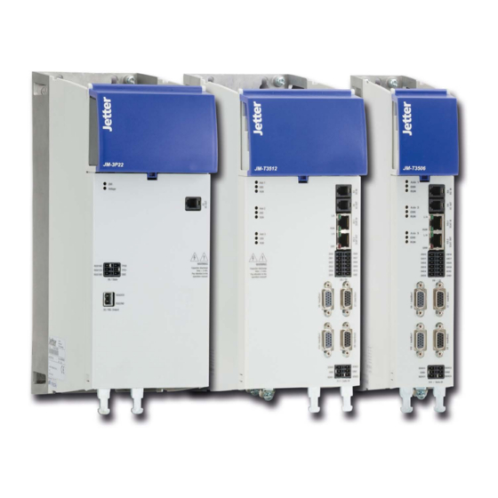
- Page 1 User Manual JetMove 3000 – Servo Amplifier 608880297 We automate your success...
- Page 2 In the case of modifications, further developments or enhancements to products shipped in the past, a revised docu- ment will be supplied only if required by law, or deemed appropriate by Jetter AG. Jetter AG shall not be liable for any errors either in form or content, or for any missing updates, as well as for any damage or detriment resulting from such failure.
-
Page 3: Table Of Contents
JetMove 3000 Table of contents Safety ................... 12 Measures to ensure your safety ..................12 Warning symbols ......................13 Intended use .........................13 Usage other than intended....................14 EC declaration of conformity ..................15 Responsibility ........................17 Maintenance and repairs ....................17 Repairs ..........................17 Mechanical installation..............18 Mounting instructions ....................18 2.9.1... - Page 4 6.32.26 Current data - Control unit of servo amplifier (3.0 A) ........93 6.33 Ambient conditions .......................94 6.34 Certifications .........................96 6.34.27 CE certification ....................96 6.34.28 UL certification ....................96 6.34.29 Retroactive grid load due to harmonics ............96 6.35 Accessories ........................97 6.35.30 Connection cables for communication ............97 Jetter AG...
- Page 5 JetMove 3000 Navigating through this document In order that you can commission your new JM-3000 as quickly and smoothly as possible, we ask that you first read through this user manual thoroughly and carefully. Step Action Comment With this user manual, you will...
- Page 6 JetMove 3000 Safety Mechanical installation Electrical installation Commissioning Diagnostics Safety features (STO and SBC) Appendix Documentation for JM-3000 Document Content Item number Format JM-3000 Supply Unit - Installation, mounting, safety, 60880298 User Manual specification JM-3000 Servo Amplifier Installation, mounting, safety,...
- Page 7 S1 = ST0 (Safe Torque Off) + SBC (Safe Brake Control) S2 = Extended functional safety (e.g. SLS, SLT, ...) for encoder resolver and HIPERFACE DSL® = Standard, EtherCAT (JX4 Jetter bus) = No option TD = HIPERFACE DSL = No braking resistor...
- Page 8 JetMove 3000 Manufacturing data You will find the serial number on the nameplate of JM-3000 servo amplifier, from which you can read the date of manufacture according to the following code. The location of the nameplate on the JM-3000 can be seen on Fig.
- Page 9 JetMove 3000 A second nameplate (T1) with only the most important information is lo- cated on the top of the busbar cover. This means that the nameplates are readable even when the devices are installed in a row. Fig. 0.4...
- Page 10 JetMove 3000 Pictograms Pictograms are used in these operating instructions to improve orientation; their meaning is described in the following table. The meaning of each pic- togram is always the same even when it appears without text such as when it is placed next to a connection diagram.
-
Page 11: Safety
JetMove 3000 Safety Safety Measures to ensure your safety The following instructions must be read before initial commissioning to avoid injury and/or damage to property. Observe the safety instructions at all times. First read the operating instructions! Do not start the implementation until you have understood these instructions. -
Page 12: Warning Symbols
The JM-3000 multi-axis motion system consists of at least one supply unit and at least one servo amplifier. In motor operating mode, the supply unit draws power from the supply network and provides it to the connected servo amplifiers via the DC link. Jetter AG... -
Page 13: Usage Other Than Intended
JetMove 3000 Safety When the servo amplifier is installed in a machine, commissioning (i.e. commencement of DES intended use) is prohibited until it has been de- termined that the machine complies with Machinery Directive 2006/42/EC. Commissioning, i.e. the commencement of the intended use is only permit- ted if the EMC Directive (2004/108/EC) is complied with. -
Page 14: Ec Declaration Of Conformity
Safety eC declaration of conformity According to Machinery Directive 2006/42/EC EU-Konformitätserklärung EC declaration of conformity Hersteller / manufacturer Jetter AG Gräterstr. 2 D-71642 ludwigsburg Geräteart / model: Servoverstärker inkl. option S1 / Servoamplifier incl. option S1 Produkt / product: Serie JM-35xx-S1Ay... - Page 15 Gestaltungsleitsätze; Safety of machinery - Safety-related parts of control systems - General principles for design; Zur Zusammenstellung technischer Unterlagen bevollmächtigte Person Authorised person for compiling technical files Jetter AG, Gräterstr. 2, D-71642 Ludwigsburg Ort / place: Ludwigsburg Datum / date: 10.05.2019...
-
Page 16: Responsibility
Repairs Only authorized repair centers are permitted to carry out repairs. Unauthor- ized tampering can lead to death, personal injury and damage to property. The warranty provided by Jetter AG is rendered void. Jetter AG... -
Page 17: Mechanical Installation
JetMove 3000 Mechanical installation Mechanical installation Mounting instructions AvoiD At All CoStS thAt ... ƒ moisture enters into the device ƒ drill chips, screws or foreign objects fall into the device. Please note: This device is intended exclusively for installation inside a stationary ƒ... -
Page 18: Order And Arrangement
100 °C can occur on the heat sink of the unit. Please ensure that there is sufficient distance to adjacent modules, especially above the heat sink, CAUtIoN Protection against hot surfaces during operation. Provide suitable protection against accidental contact with the heat sink. Jetter AG... -
Page 19: Mounting Clearances
JetMove 3000 Mechanical installation Mounting clearances CAUtIoN The minimum clearances specified in Fig. 2.1 above, below and in front of the device applies to all units (JM-3000 supply unit and JM-3000 servo amplifiers). The clearance above is important to avoid heat accumulation, the clearance from the bottom and the front to allow correct cable routing. -
Page 20: Cooling Of Devices
(= heat loss is dissipated to the outside via the control cabinet walls), always provide an internal fan. If the unit is switched off due to excessive temperature, the cooling conditions must be improved. Fig. 2.3 Cooling air flows unhindered through the unit Jetter AG... -
Page 21: Mounting Wall-Mount Devices
JetMove 3000 Mechanical installation Mounting wall-mount devices Step Action Comment Arrange the units on the mounting plate as shown Fig. 2.1. This is necessary to be able to connect the DC link Align all devices of the multi-axis system in one busbars. - Page 22 Mechanical installation Fig. 2.4 Dimensioned drawing of JM-3000 servo amplifier BG1 (dimensions see Table 2.1) Jetter AG...
- Page 23 JetMove 3000 Mechanical installation Fig. 2.5 Dimensioned drawing of JM-3000 servo amplifier BG2 (dimensions see Table 2.1) Jetter AG...
-
Page 24: Mounting Coldplate Devices
D (depth) 188.5 27.5 27.5 Lateral distance Can be lined up without gap C (screws) 2 x M4 4 x M4 All dimensions in mm Drawing see Fig. 2.3 and Fig. 2.5 Table 2.2 Dimensions and mounting distances Jetter AG... - Page 25 JetMove 3000 Mechanical installation Fig. 2.6 Dimensioned drawing of JM-3000 servo amplifier BG1 ColdPlate(dimensions see Table 2.2) Jetter AG...
- Page 26 Mechanical installation Fig. 2.7 Dimensioned drawing of JM-3000 servo amplifier BG2 ColdPlate(dimensions see Table 2.2) Jetter AG...
-
Page 27: Mounting On The Cooler
JetMove 3000 Mechanical installation 2.5.2 Mounting on the cooler For optimum heat transfer from the heat sink of the unit to the corresponding cooler, a heat conducting film is already glued to the cooling plate of the unit (see Fig. 2.8). On the cooler side, the film is laminated with aluminum. -
Page 28: Dimensioning Of The Cooler
Max. temperature of cooling plate 85 °C on the device Cooler surface Maximum roughness depth R = 6.3 1) Thermal resistance between active cooling surface of the unit and cooler Table 2.3 Characteristics of ColdPlate variant Jetter AG... -
Page 29: Dimensions Of The System
JetMove 3000 Mechanical installation Dimensions of the system JM-3000 plus Safety (example: safety controller, supply unit with two servo amplifiers BG1) Fig. 2.10 JM-3000 plus Safety Jetter AG... - Page 30 Mechanical installation JM-3000 (example: supply unit with two servo amplifiers BG1) Fig. 2.11 JM-3000 Jetter AG...
- Page 31 JetMove 3000 Mechanical installation JM-3000 (example: supply unit with one servo amplifier BG1) Fig. 2.12 JM-3000 Jetter AG...
- Page 32 Mechanical installation Jetter AG...
-
Page 33: Electrical Installation
JetMove 3000 Electrical installation electrical installation Notes on installation NotICe! Qualified personnel: The installation may only be carried out by qualified personnel who is trained in electrical engineering and has been instructed in accident pre- vention measures. During the installation work: Avoid at all costs that ... -
Page 34: Installation To Emc Rules
− Avoid unnecessarily long cable lengths and loops. Note: If third-party interconnectors are used, they must be at least equivalent to those of Jetter AG. However, Jetter AG cannot guarantee stable and safe operation with such cables. Grounding measures ƒ... - Page 35 Fig. 3.1 Example: Shielding of control line connections Additional information can also be found in the description of the respective connection. If you would like more detailed information about installation, please contact the Jetter hotline (see page „Hotline/Support & Service“ auf Seite 73). Jetter AG...
-
Page 36: Overview Of Connections
State Axis 2 State Axis 3 State Axis 1 State Axis 2 State Axis 1 X3 / X4 State Axis 1 X5.1 / X5.2 S-ADR S-ADR S-ADR JM-35xx JM-D35xx JM-T35xx Fig. 3.2 Layout of JM-3000 servo amplifier series Jetter AG... - Page 37 JetMove 3000 Electrical installation Abbreviation Designation Details 24 V supply voltage of control unit See 3.6.1 on page 55. Via busbar DC link supply (DC link +/-) See 3.6.2 on page 55. Input of cross communication See 3.10 on page 66.
-
Page 38: Single-Axis Servo Amplifier
3.3.1 Single-axis servo amplifier Axis 1 Axis 1 X5.1 X5.2 DI00 DI06 DI01 DI07 DI02 DI08 DI03 DI09 DI04 DI10 DI05 X6 / DI SDI00 SDI02 SDI01 SDI03 X11 / Safe - DI Fig. 3.3 Layout of single-axis servo amplifier Jetter AG... - Page 39 JetMove 3000 Electrical installation Abbreviation Designation Details Connections for cross communication. Cross communication input Caution: Only for system-internal use/ Cross communication output communication Can also be used as Ethernet interface for X5.1 EtherCAT IN, fieldbus input X5.2 EtherCAT OUT, fieldbus output...
- Page 40 Electrical installation Fig. X8 Pin SinCos and ttl Typ. +5.15 V, 250 mA max. Table 3.4 Pin assignment of connector X8 (Enc2) - Single-axis servo amplifier Jetter AG...
-
Page 41: Twin-Axis Servo Amplifier
JetMove 3000 Electrical installation 3.3.2 twin-axis servo amplifier Axis 1 Axis 1 Axis 2 Axis 2 X5.1 X5.2 DI00 DI06 DI01 DI07 DI02 DI08 DI03 DI09 DI04 DI10 DI05 X6 / DI SDI00 SDI02 SDI01 SDI03 X11 / Safe - DI Fig. - Page 42 S4/SIN- (B-) Typ. 10 V, 110 mA max. R1 (resolver excitation +) R2 (resolver excitation -) +SIN S2/SIN+ (B+) Safety Sense+ Safety Sense- CLK+ CLK- Table 3.6 Pin assignment of connector X7 (Enc1) - Twin-axis servo amplifier, axis 1 Jetter AG...
- Page 43 JetMove 3000 Electrical installation Fig. X8 Pin SinCos and ttl Typ. +5.15 V, 250 mA max. Table 3.7 Pin assignment of connector X8 (Enc2) - Twin-axis servo amplifier, axis 1 twin-axis servo amplifier encoder of axis 2 Fig. X7 Pin...
- Page 44 Electrical installation Fig. X10 Pin SinCos and ttl Typ. +5.15 V, 250 mA max. Table 3.9 Pin assignment of connector X10 (Enc2) - Twin-axis servo amplifier, axis 2 Jetter AG...
-
Page 45: Triple-Axis Servo Amplifier
JetMove 3000 Electrical installation 3.3.3 triple-axis servo amplifier Axis 1 Axis 1 Axis 2 Axis 2 X5.1 Axis 3 Axis 3 X5.2 DI00 DI06 DI01 DI07 DI02 DI08 DI03 DI09 DI04 DI10 DI05 X6 / DI SDI00 SDI02 SDI01 SDI03 X11 / Safe - DI Fig. - Page 46 LED (amber) Status of axis 2 LED (red) Details see chapter 4.1 LED, green Axis 3 LED (amber) Status of axis 3 LED (red) Details see chapter 4.1 LED, green Table 3.10 Legend: Wiring diagram of triple-axis servo amplifier Jetter AG...
- Page 47 JetMove 3000 Electrical installation triple-axis servo amplifier encoder of axis 1 Fig. X7 Pin SinCos and ttl enDat/SSI HIPeRFACe® Resolver REFCOS S3/COS- (A-) +COS S1/COS+ (A+) Typ. +5.15 V, 250 mA max. Data+ Data- REFSIN S4/SIN- (B-) Typ. 10 V, 110 mA max.
- Page 48 S4/SIN- (B-) Typ. 10 V, 110 mA max. R1 (resolver excitation +) R2 (resolver excitation -) +SIN S2/SIN+ (B+) Safety Sense+ Safety Sense- CLK+ CLK- Table 3.13 Pin assignment of connector X9 (Enc1) - Triple-axis servo amplifier, axis 2 Jetter AG...
- Page 49 JetMove 3000 Electrical installation triple-axis servo amplifier encoder of axis 3 Fig. X7 Pin SinCos and ttl enDat/SSI HIPeRFACe® Resolver REFCOS S3/COS- (A-) +COS S1/COS+ (A+) Typ. +5.15 V, 250 mA max. Data+ Data- REFSIN S4/SIN- (B-) Typ. 10 V, 110 mA max.
-
Page 50: Connecting The Protective Earth Conductor
Netz/Line Last/Load Fig. 3.6 Protective conductor connection of the JM-3000 sys- 1) Supply unit 2) Servo amplifiers 3) Servo amplifiers 4) Line reactor 5) Line filter 6) Grounding in series from below 7) Alternative ground connection from above Jetter AG... - Page 51 JetMove 3000 Electrical installation Note: The respective local and national regulations and conditions must always be observed. Netz/Line Last/Load Fig. 3.7 Connection of the JM-3000 system with double PE cables 1) JSC-3000 safety controller 2) Supply unit 3) Servo amplifiers...
-
Page 52: Electrical Isolation Concept
PELV (Protective Extra Low Voltage) = protective low voltage AC: U ≤ 50 V One connection of the extra low voltage is grounded. Secure isolation from low-voltage and PELV network Table 3.15 Key to "Electrical isolation concept" overview Jetter AG... - Page 53 JetMove 3000 Electrical installation +24 V PELV 24 V PELV DC Link+ DC Link - ϑ n.c. PELV PELV PELV ϑ ϑ X5.1 X5.2 PELV PELV PELV PELV PELV PELV PELV PELV Mains Mains ϑ Motor n.c. L1.1 L1.1 L2.1 L2.1...
-
Page 54: Connecting The Supply Voltages
Make sure that all connections have good contact and are screwed tight with sufficient torque (2.1 Nm) so that they cannot come loose by themselves. Jetter AG does not assume any liability for stable and safe operation when using connecting elements that do not comply with the specifications. -
Page 55: Controller Supply Voltage (+24 V Dc)
JetMove 3000 Electrical installation 3.6.1 Controller supply voltage (+24 v DC) Fig. Specification • U = +24 V DC ± 20 % stabilized and smoothed • Permanent output power of the switching power supply unit max. 470 W • Internal polarity reversal... -
Page 56: Overview Of Busbar Connections
Operation of the multi-axis system is only permitted when the busbar covers are closed! It is also important that the side covers (A) are inserted. Both provide Death or serious injury will protection against contact with bare and live parts. result if the appropriate precautions are not taken. Jetter AG... -
Page 57: Control Terminals
JetMove 3000 Electrical installation Control terminals Step Action Comment Cross communication Connect terminal X3 of the supply unit to terminal see chapter 3.10 X3 of the first servo amplifier. Then connect termi- nal X4 of the first servo amplifier to X3 of the next servo amplifier, etc. -
Page 58: Digital Inputs At X6 (Standard Functions)
Table 3.16 Assignment of the control inputs (Example: triple-axis servo amplifier) Specification of the terminals The X6 control terminal is implemented with a 2-level 2x 6-pole plug-in terminal with 3.5 mm pitch from Phoenix-Contact. − Type: MCDN 1.5/6-G1-3.5 Jetter AG... -
Page 59: Digital Inputs At X11 (Safe Digital Inputs)
JetMove 3000 Electrical installation 3.7.2 Digital inputs at X11 (safe digital inputs) Safe digital inputs are connected to terminal X11. Fig. type Features SDI00 Safe digital input STO 1 CH1 X11/Safe DI SDI01 Safe digital input STO 1 CH2 SDI00... - Page 60 CAUtIoN If a ground fault or short circuit occurs in the motor cable during opera- tion, the output stage is disabled and an error message is sent. The motor coasts to a stop. Jetter AG...
-
Page 61: Motor Connection
Motor cable All motor cables must be shielded. To connect servo motors, use ready- made motor cables from Jetter AG. The available cables are listed in the appendix in Tabelle A.8. Equivalent shielded cables must be used for the connection of third-party motors. -
Page 62: Monitoring Of Output For Motor Holding Brake
M = motor connector Twin-axis servo amplifier 60879943_00 Triple-axis servo amplifier 60879944_00 * In addition to the motor connectors, the connector set also contains the connectors for the control terminals (X6 and X11). Table 3.18 Specification of motor terminals X12/X13/X14 Jetter AG... -
Page 63: Switching Operations In The Motor Cable
All encoder connections are located on the top of the device. encoder connection of Jetter motors To connect synchronous motors by Jetter AG, use pre-assembled motor and encoder cables from Jetter AG (see Accessories Catalog). Matching of motor encoder cable and servo amplifier Compare the nameplates of the components. -
Page 64: Connecting High-Resolution Encoders
5 Diagnose 5 Diagnose Note: ƒ The use of encoders not included in the Jetter product range requires a special release through Jetter AG. ƒ The maximum signal input frequency is 500 kHz. ƒ Encoders with a supply voltage of 5 V ± 5 % must have a separate... -
Page 65: Connecting An Additional Encoder (X8)
Table 3.21 Supported encoder types for use at X8 X11 / Safe - DI X11 / Safe - DI The use of encoders not included in the Jetter product range requires a ƒ special release through Jetter AG. Siehe Kapitel... -
Page 66: Specification Of Cross Communication
Connections must be made before commissioning, otherwise error messages will occur. Connection example: SDI00 SDI02 SDI01 SDI03 X11 / Safe - DI Siehe Kapitel 5 Diagnose Fig. 3.15 Connection example of cross communication Jetter AG... -
Page 67: Ethercat Interface Specification
3.11 EtherCAt interface specification The EtherCAT fieldbus interface X5.1 is typically intended for the connection of JetControl controllers by Jetter AG with EtherCAT master. It can also be used as a service and diagnostic interface. However, it can then only be used for connecting a PC for commissioning, service and diagnostics tasks by means of the JetSym software tool (if you have any questions, please contact us). -
Page 68: Connection Example - Supply Unit/Servo Amplifier
+24 V 24 V DC Link+ DC Link - ϑ n.c. ϑ ϑ X5.1 X5.2 n.c. L1.1 L1.1 L2.1 L2.1 L3.1 L3.1 17 18 Motor Motor Motor ϑ ϑ ϑ L1 L2 L3 Fig. 3.17 Connection example (schematic diagram) Jetter AG... - Page 69 JetMove 3000 Electrical installation Callout - Connection example Designation Mains fuses for DC link supply Mains fuse for switching power supply unit Mains contactor with protective circuit Line reactor (option) Line filter (option) AC mains connection (power supply) AC mains connection (24 V switching power supply unit)
- Page 70 Jetter AG...
-
Page 71: Diagnostic Functions
JetMove 3000 Diagnostic functions Diagnostic functions leDs: Axis status Depending on the version of the servo amplifier (single-axis amplifier, dual- axis amplifier, triple-axis amplifier) up to three LEDs are provided as status indicators. The LEDs are located on the front panel of the device and are assigned to axis 1 to axis 3 from top to bottom. -
Page 72: Flashing Code
= Interface X5.1 switches over with the next power on = Interface is in Ethernet mode, additionally the "RUN" LED at X5.1 flickers. Status: Flash- = Interface works in EtherCAT mode Status: OFF Table 4.1 Status LEDs - Flashing code Jetter AG... -
Page 73: Hotline, Support And Service
Internet: www.jetter.de ►Support NotICe: If you need consultation beyond the scope of the hotline, you will find all offered services in the industry catalog. You can download the Industry Automation catalog from our website http://www.jetter.de under the heading "Quicklinks". Jetter AG... - Page 74 Diagnostic functions Jetter AG...
-
Page 75: Standard Version S1
JetMove 3000 Standard version S1 Standard version S1 The S1 version includes the safety functions STO (Safe Torque Off) and SBC (Safe Brake Control). They are controlled via safe digital inputs on the control board of the servo amplifier. NOTE: All further information on the "STO"... - Page 76 Standard version S1 Jetter AG...
-
Page 77: Appendix
JetMove 3000 Appendix Appendix A.1 technical Data of JM-3000 Servo Amplifier, Part 1 JM-3000 servo amplifier Unit JM-D3503 JM-t3503 Control section Control voltage V DC 24 ± 20 % Control voltage when using a motor holding brake with V DC 24 - 5 %/+ 10 % cable length <... -
Page 78: Current Data Of Jm-3000 Switching Device
= 0 Hz 2 x 4.0 3 x 4.0 Notes: Current data per axis in the servo amplifier 230/400/480 V AC refers to the supply voltage of the supply unit. Table A.2 Current data of the 3 amp servo amplifiers Jetter AG... - Page 79 JetMove 3000 Appendix JM-3000 servo amplifier Unit JM-D3503 JM-t3503 Mains Rated current 2 x 2 3 x 2 Maximum current for 10 s 2 x 4 3 x 4 400 V 12 kHz Maximum current for 500 ms 2 x 4.85 3 x 4.85...
-
Page 80: Technical Data Of Jm-3000 Servo Amplifier, Part 2
Typical current consumption - encoder channel 4 SinCos/TTL 1) Typical current consumption - encoder HIPERFACE/HIPERFACE DSL 1) Typical total current consumption - servo amplifier with air cooling Typical total current consumption - servo amplifier with ColdPlate 1) Current consumption may vary depending on encoder type Jetter AG... -
Page 81: Control Unit - Current Data (Jm-3Xxx 12.0 A)
JetMove 3000 Appendix JM-3000 servo amplifier Unit JM-3512 JM-D3512 JM-t3512 Control section Control voltage V DC 24 ± 20 % Control voltage when using a motor hold- V DC 24 - 5 %/+ 10 % ing brake with cable length < 50 m Max. -
Page 82: Control Unit - Current Data (Jm-3Xxx 16
Typical current consumption - encoder channel 4 SinCos/TTL 1) Typical current consumption - encoder HIPERFACE/HIPERFACE DSL 1) Typical total current consumption - servo amplifier with air cooling Typical total current consumption - servo amplifier with ColdPlate 1) Current consumption may vary depending on encoder type Jetter AG... -
Page 83: Control Unit - Current Data (Jm-3Xxx 24
JetMove 3000 Appendix JM-3000 servo amplifier Unit JM-3524 JM-3532 Control unit Control voltage V DC 24 ± 20 % Control voltage when using a motor holding brake with V DC 24 - 5 %/+ 10 % cable length < 50 m Max. -
Page 84: Switching Device - Current Data Jm-3Xxx 6
= 0 Hz 2 x 8 3 x 8 Notes: Current data per axis in the servo amplifier 230/400/480 V AC refers to the supply voltage of the supply unit. Table A.7 Current data of the 6 amp servo amplifiers Jetter AG... - Page 85 JetMove 3000 Appendix JM-3000 servo amplifier Unit JM-3506 JM-D3506 JM-t3506 Mains Rated current 2 x 4 3 x 4 Maximum current for 10 s 2 x 8 3 x 8 400 V Maximum current for 500 ms 2 x 9.7 3 x 9.7...
- Page 86 10.5 2 x 13.7 3 x 13.7 Notes: Current data per axis in the servo amplifier 230/400/480 V AC refers to the supply voltage of the supply unit. Table A.8 Current data of the 12 amp servo amplifiers Jetter AG...
- Page 87 JetMove 3000 Appendix JM-3000 servo amplifier Unit JM-35012 JM-D3512 JM-t3512 Mains Rated current 2 x 5.1 3 x 5.1 Maximum current for 10 s 2 x 10.2 3 x 10.2 400 V Maximum current for 500 ms 2 x 14.7 3 x 14.7...
- Page 88 Notes: Current data per axis in the servo amplifier 230/400/480 V AC refers to the supply voltage of the supply unit. 2) for 2 s 3) for 3 s Table A.9 Current data of the 16 and 18 amp servo amplifiers Jetter AG...
- Page 89 JetMove 3000 Appendix JM-3000 servo amplifier Unit JM-3518 JM-D3516 Mains Rated current 2 x 6.8 Maximum current for 10 s 19.3 2 x 13.6 400 V Maximum current for 500 ms 19.3 2 x 14.7 Maximum current at F = 0 Hz 12.3...
- Page 90 = 0 Hz 18.2 Notes: Current data per axis in the servo amplifier 230/400/480 V AC refers to the supply voltage of the supply unit. 2) for 2 s Table A.10 Current data of the 32 amp servo amplifiers Jetter AG...
-
Page 91: Current Data - Control Unit Of Servo Amplifier (3.0 A)
JetMove 3000 Appendix JM-3000 servo amplifier Unit JM-3524 JM-3532 Mains Rated current 14.1 Maximum current for 10 s 22.9 28.2 400 V Maximum current for 500 ms 22.9 35.3 Maximum current at F = 0 Hz 13.4 36.35 Rated current... -
Page 92: Ambient Conditions
This means that the maximum values listed in the table for temperature and relative humidity must not occur at the same time. Table A.12 Climatic conditions JM-3000 Note: The climatic conditions apply to the unit. For this reason, they must also be met in the control cabinet. Jetter AG... - Page 93 JetMove 3000 Appendix Mechanical conditions JM-3000 To EN 61800-2, IEC 60721-3-2 class 2M1 Frequency [Hz] Amplitude [mm] Acceleration [m/s²] Vibration limit during 2 ≤ f < 9 Not applicable transport 9 ≤ f < 200 Not applicable 200 ≤ f < 500...
-
Page 94: Certifications
If our drive units are used as a component in your machine/plant, you must check if the standard applies to the complete machine/plant. Jetter AG... -
Page 95: Accessories
(for use with the JM-3000 supply unit). A.7.1 Connection cables for communication Type: XCOM Jetter item number: 60879945_00 Communication cable set JM-3000, 1 piece each: • RJ-10 cross communication, 0.25m • RJ-45 patch cable SF/UTP, Cat 5e, 0.25m... - Page 96 Jetter AG Graeterstr. 2 71642 Ludwigsburg / Germany Phone +49 7141 2550-0 Fax +49 7141 2550-425 info@jetter.de www.jetter.de We automate your success...
Need help?
Do you have a question about the JetMove 3000 and is the answer not in the manual?
Questions and answers