Table of Contents
Advertisement
Quick Links
Advertisement
Table of Contents

Subscribe to Our Youtube Channel
Related Manuals for Jetter JM-108


Summary of Contents for Jetter JM-108
- Page 1 User Manual JM-108 - Digital Servo Amplifier 60875640 We automate your success.
- Page 2 Item # 60875640 Revision 2.16.1 September 2017 / Printed in Germany Jetter AG reserve the right to make alterations to its products in the interest of technical progress. These alterations will not necessarily be documented in every single case. This manual and the information contained herein have been compiled with due diligence.
- Page 3 JetMove 108 Introduction How to Contact us: Jetter AG Graeterstrasse 2 D-71642 Ludwigsburg Germany Phone - Switchboard: ++49 7141/2550-0 Phone - Sales: ++49 7141/2550-433 Phone - Technical Hotline: ++49 7141/2550-444 Telefax - Sales: ++49 7141/2550-484 E-Mail - Sales: sales@jetter.de E-Mail - Technical Hotline: hotline@jetter.de...
- Page 4 Missing or inadequate knowledge of the manual results in the loss of any claim of liability on part of Jetter AG. Therefore, the operating company is recommended to have the instruction of the persons concerned confirmed in writing.
- Page 5 Note · / - Enumerations are marked by full stops, strokes or scores. Operating instructions are marked by this arrow. Automatically running processes or results to be achieved are marked by this arrow. Jetter AG...
- Page 6 Introduction Reference to PC keyboard and HMI keys. This symbol informs you of additional references (data sheets, literature, etc.) associated with the given subject, product, etc. Further, this text provides helpful hints for your guidance through the manual. Jetter AG...
-
Page 7: Table Of Contents
Description of Connections Demands on the Power Supply Unit for Motor Operating Voltage 7.1.1 Recommendations on the power supply circuit breaker +Vmot 7.1.2 General remarks 7.1.3 Recommendations on preventing overvoltage at braking or lowering a vertical load Power Supply Jetter AG... - Page 8 7.8.1 Specification Connection of the Incremental Encoder 7.9.1 Specification 7.10 Digital and Analog Inputs and Outputs 7.11 Jetter System Bus 7.11.1 JETTER System Bus Cable Specification Status Monitoring Diagnostics Error Messages Alarms Wiring Diagrams Ordering Information 11.1 List of Documentation 11.2...
- Page 9 JetMove 108 Table of Contents Appendix A: Recent revisions Appendix B: Glossary Appendix C: List of Illustrations Appendix D: Index Jetter AG...
- Page 10 Table of Contents JetWeb Jetter AG...
-
Page 11: Safety Instructions
The servo amplifier JetMove 108 is not a safety-relevant device according to the machinery directive 2006/42/EG. Therefore, using this servo amplifier for safety-relevant applications as regards safety of persons is neither adequate nor permitted. Jetter AG... -
Page 12: Personnel Qualification
The installation of such parts may impair the safety and the proper functioning of the digital servo amplifier JetMove 108. Any liability on the part of Jetter AG for any damages resulting from the use of non- original parts and equipment is excluded. -
Page 13: Repair And Maintenance
The servo amplifier JetMove 108 does not contain any parts to be repaired by the operator. For being repaired, the servo amplifier JetMove 108 must be sent to Jetter AG. The digital servo amplifier JetMove 108 is maintenance-free. Therefore, absolutely no inspection or maintenance works are required for the operation of this device. -
Page 14: Ensure Your Own Safety
Secure the servo amplifier JetMove 108 against misuse or accidental use. 1.2.2 Information Signs and Labels Follow the instructions given on markings, information signs, and labels. Keep markings, signs and labels readable. Replace damaged or unreadable information signs and labels. Jetter AG... -
Page 15: Earthing Procedure
Make sure that no temperature-sensitive parts have been connected or fastened to the servo amplifier JetMove 108. DANGER in a potentially explosive atmosphere! Do not operate the digital servo amplifier JetMove 108 in a potentially explosive atmosphere. Warning Jetter AG... -
Page 16: Instructions On Emc
The electromagnetic immunity of a system depends on the weakest component of the system. For this reason, correct wiring and shielding of cables is of paramount importance. Important! Measures for increasing EMC in electric plants: Earth the device adequately according to chapter 1.2.3 "Earthing procedure", page 15. Jetter AG... - Page 17 Follow the instructions given in Application Note 016 "EMC-Compatible Installation of the Electric Cabinet" published by Jetter AG. The following instructions are excerpts from Application Note 016: Screw the enclosure of the digital servo amplifier JetMove 108 down to a highly conducting, plane and earthed panel.
- Page 18 When doing so, grounding must be implemented in a way that the unshielded portion of the cable is as short as possible (refer to Fig. 2). JetMove 108 Shield Metal Rail Motor Cable Fig. 2: Shielding of screw terminals to EMC standards Jetter AG...
-
Page 19: Installing The Jetmove
Motor power cable, see also chapter 7.3 "Servo Motor", page 52. • Encoder cable, see also chapter 7.7 "Connection of the Resolver", page 71. • Motors, e.g. synchronous servo motors of the Jetter motor series JL1 or JH2. • DC power supply unit •... -
Page 20: Mechanical Installation
Screw the lower fitting screws into the thread by approximately half of their length. By means of the oblong holes in the rear plate, hang up the JetMove 108 by the fitting screws; then screw them down tightly. Screw down the upper fitting screws. Jetter AG... - Page 21 JetMove 108 2.2 Mechanical Installation m i n . 2 5 m m Fig. 3: Recommended mounting Jetter AG...
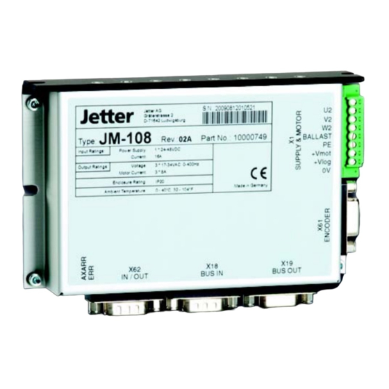
- Page 22 2 Installing the JetMove 108 Jetter Jetter AG Gräterstrasse 2 D-71642 Ludwigsburg JM-108 JM-108 Type: Rev.: Part No.: 10000749 BALLAST Input Ratings: Power Supply: 1 * 24-48VDC Current: +Vmot Output Ratings: Voltage: 3 * 17-34VAC, 0-400Hz +Vlog Motor Current: 3 * 8A...
-
Page 23: Electrical Installation
Check whether the ground cable is connected. To connect resolvers or power units you can use prefabricated cables available from Jetter or opt for self-made cables. Please refer to chapter 7 "Description of Connections", page 43. To ensure that installation is carried out in conformance with EMC regulations, the following items have to be observed especially: –... -
Page 24: Checking The Installation
Check the holding brake, if existing, for proper functioning. Check to see whether all necessary protection measures against accidental contact with live or moving parts have been taken. Carry out any other checks specific to or required for your system. Jetter AG... -
Page 25: Notes On Safety As Regards Commissioning
Accordingly, do only connect encoders with the servo amplifier, if they have been sufficiently isolated from the connected mains and motor power supply. Always carry out each commissioning, even a short functional test, with correctly connected PE bus; Jetter AG... - Page 26 2 Installing the JetMove 108 Jetter AG...
-
Page 27: Operating Conditions
Max. operating Up to 1,000 m above sea level. DIN EN 50178 altitude From 1,000 to 2,500 m above sea level: derating of 1.5% per 100 m increase in alitude Jetter AG... - Page 28 Protective network conductor and DIN EN 61800-5-1 Ω network logics: > 1 M at 500 V Ω Protective < 60 V, 25 A, 0.1 DIN EN 61800-5-1 Connection Overvoltage DIN EN 61800-5-1 category DIN EN 50178 DIN VDE 0110-1 UL 508C Jetter AG...
- Page 29 3 installation) Important! This is a product of restricted availability according to IEC/EN 61800-3. This module can cause radio interferences in residential areas. In this case, the user must take adequate measures to prevent this. Jetter AG...
- Page 30 Acceptance criterion B environment, cat. 3 installation) Guided radio Frequency 0.15 ... 80 MHz DIN EN 61800-3 disturbances Test voltage 10 V DIN EN 61000-4-6 AM 80 % with 1 kHz Acceptance criterion A environment, cat. 3 installation) Jetter AG...
- Page 31 Acceptance criterion B environment, cat. 3 installation) Guided radio Frequency 0.15 ... 80 MHz DIN EN 61800-3 disturbances Test voltage 3 V DIN EN 61000-4-6 AM 80 % with 1 kHz Acceptance criterion A environment, cat. 3 installation) Jetter AG...
- Page 32 3 Operating Conditions Jetter AG...
-
Page 33: Physical Dimensions
JetMove 108 Physical Dimensions 26,5 58,8 90,9 Jetter Jetter AG Gräterstrasse 2 D-71642 Ludwigsburg JM-108 Type: Rev.: Part No.: 10000749 BALLAST Input Ratings: Power Supply: 1 * 24-48VDC Current: +Vmot Output Ratings: Voltage: 3 * 17-34VAC, 0-400Hz +Vlog Motor Current:... - Page 34 4 Physical Dimensions Jetter AG...
-
Page 35: Technical Specifications
The voltage output has to comply with the power supply unit of the SELV or PELV type. Inrush current limitation The JM-108 is equipped with an internal 200 µF capacitors for buffering. The inrush current is not limited. See "Recommendations on the power supply circuit breaker +Vmot"... - Page 36 The voltage output has to comply with the power supply unit of the SELV or PELV type. Inrush current limitation of the The JM-108 is equipped with an internal processor logics 200 µF capacitors for buffering. The inrush current is not limited.
- Page 37 • The overtemperature alarm is activated at 80 °C Compatible Synchronous Servo Motors Motor types Jetter motors of the JL1 and JH2 series. Please refer to "Jetter Motor Catalog" or contact the sales department of Jetter AG. Note! In case you intend to use motors other than the above mentioned types, please contact Jetter AG.
-
Page 38: Motor Protection
The time till error trip (x = 100 %) is a result of the following formula: nominal current × – – ---------------------------------------------------- - average motor current Jetter AG... - Page 39 JetMove 108 is switched on (i. e. at the time of parameters of I²t calculation are written after switching on 24 V logic power supply). Important For this reason, please wait, until the motor has cooled down before re-enabling the axis. Jetter AG...
- Page 40 5 Technical Specifications Jetter AG...
-
Page 41: Drive Controller Structure
JetMove 108 Drive Controller Structure Fig. 6: Block Diagram of Drive Controller Structure Jetter AG... - Page 42 – Resolution 12 bits per revolution – Sampling interval 62.5 µs Sine/cosine encoder: – Resolution of absolute position 15 Bit per encoder period – Resolution of velocity pickup 20 Bit per encoder period – Sampling interval 62.5 µs Jetter AG...
-
Page 43: Description Of Connections
The power supply voltage is rated at the required speed and torque: Where: n ⋅ ------------- - 1000 Counter-EMF U in Volt (V) Back EMF constant K in V*min/1000 Revolutions n in 1/min Voltage U generating the required torque at maximum RPM. Jetter AG... -
Page 44: Recommendations On The Power Supply Circuit Breaker +Vmot
8), and NOT at its output, i.e. between power supply unit and servo amplifier. This way, the current-limiting circuitry of the power supply is used to limit the inrush current of the JetMove 108. Power supply unit JetMove 108 +Vmot Circuit breaker Fig. 8: Terminal X1 - Recommended inrush current limitation Jetter AG... -
Page 45: General Remarks
Apply a short connection of a large cross-section between the PE of the servo amplifier and the connection to ground. Whenever this is possible, mount the JetMove 108 on a metallized and earthed surface. Jetter AG... -
Page 46: Recommendations On Preventing Overvoltage At Braking Or Lowering A Vertical Load
= 9.81 m/s : Height before deceleration [m] : Height after deceleration [m] : Motor current during deceleration [A] : Resistance of the motor [ ] Ω : Delay time [s] : Friction torque of the motor [Nm] Jetter AG... - Page 47 Ω : Delay time [s] : Friction power of the motor [N] If the calculation described above cannot be carried out because of missing values, a good starting value for the capacitor is 10,000 µF / 100 V. Jetter AG...
- Page 48 > ------------------------------- - ⋅ Cycle Where: : Time interval between two delays in case of recurring motions Cycle = 8 A 4. Selection by means of average power and peak value: ⋅ --------------- - Cycle -------------- - Peak Jetter AG...
- Page 49 During operation or during the cooling-off period after the power has been turned off, do touch the braking resistor. Caution Please make sure that no temperature-sensitive parts have been connected or fastened to the braking resistor. Note! Options 1 and 2 can also be combined. Jetter AG...
-
Page 50: Power Supply
No inrush current limitation Power supply of 24 V DC (12 .. 30 V) the logic unit = 250 mA at 24 V max. No inrush current limitation Zero potential Ground reference for +V for the power supply Jetter AG... - Page 51 JetMove 108 7.2 Power Supply JetMove 108 X1 - Voltage Supply and Motor Connections (optional) Connected with Enclosure 24 / 48V DC 24 V DC Fig. 10: X1 - Supply Voltage Jetter AG...
-
Page 52: Servo Motor
Motor phase 1 Motor cable Motor phase 2 Motor cable Motor phase 3 Motor cable BALLAST Ballast resistor An optional ballast resistor can be connected between this terminal and ground. PE conductor The PE conductor is connected to the enclosure. Jetter AG... - Page 53 The brake has to be operated through a separately shielded brake line. Important! Measures to avoid oscillation and blocking of the motor: Avoid mixing-up of the motor phases, resp. be sure to connect the motor phase cables according to the pin assignment. Jetter AG...
-
Page 54: Motor With Male Connector
At the cable ends, male connectors have been fixed that correspond to the pre-fabricated JetMove 108 connection cables (See "Pre-fabricated motor cable with SC mating connector" on page 56. und “Resolver Cable With Mating Connector” on page 71). Motor specification: S4-xxx.x for JH2 and JL1 motors Jetter AG... -
Page 55: Motor With Screw Clamping Terminals And Cables With Male Connectors
The cable ends are not equipped with connectors. This way, the motor cable can be connected with the JetMove 108 directly. The feedback cable has to be connected with a SUB-D male connector. Motor specification: S3-xxx.x for JH2 and JL1 motors Jetter AG... -
Page 56: Pre-Fabricated Motor Cable With Sc Mating Connector
Note! The motor cable with the SC mating connector matching the Jetter motor series JH can be obtained from Jetter AG. It is confectioned with the matching motor mating connector and can be ordered by the following order reference: Without Brake:... - Page 57 Connect both sides of the shield with the greatest possible surface area! Use metallized housing only! Wire Number Signal X1.U2 Phase 1 X1.V2 Phase 2 X1.W2 Phase 3 X1.PE Yellow-green PE conductor Dimensions of the motor mating connector are specified in millimeters. Jetter AG...
- Page 58 Use metallized housing only! Wire Number Signal X1.U2 Phase 1 X1.V2 Phase 2 X1.W2 Phase 3 X1.PE Yellow-green PE conductor X62.2 Brake + X62.1 Brake - Dimensions of the motor mating connector are specified in millimeters. Jetter AG...
-
Page 59: Motor Cable Permanently Fixed To The Motor
Shielded, highly flexible 6-wire cable with PE. The wires are equipped with wire end ferrules. Connect shield with the greatest possible surface area! Wire Number Signal X1.U2 Phase 1 X1.V2 Phase 2 X1.W2 Phase 3 X1.PE Yellow-green PE conductor Jetter AG... - Page 60 The wires are equipped with wire end ferrules. Connect shield with the greatest possible surface area! Wire Number Signal X1.U2 Phase 1 X1.V2 Phase 2 X1.W2 Phase 3 X1.PE Yellow-green PE conductor X62.2 Brake + X62.1 Brake - Jetter AG...
-
Page 61: Brush-Type Dc Motor
Specification amplifier side Motor phase + Motor cable Motor phase - Motor cable BALLAST Ballast Resistor An optional ballast resistor can be connected between this terminal and ground. PE conductor The PE conductor is connected to the enclosure. Jetter AG... - Page 62 24 / 48V DC 24 V DC Fig. 16: X1 - DC motor connection Important! Alternative measures to avoid malfunctions of the control system and the motor: The brake has to be operated through a separately shielded brake line. Jetter AG...
-
Page 63: 2-Phase Stepper Motor
Terminals X1 on the Signal Specification amplifier side Motor phase 1+ Motor cable Motor phase 1 - Motor cable Motor phase 2+ Motor cable Ballast Motor phase 2 - Motor cable PE conductor The PE conductor is connected to the enclosure. Jetter AG... - Page 64 Connected with Enclosure 24 / 48V DC 24 V DC Fig. 17: X1 - Stepper motor connection Important! Alternative measures to avoid malfunctions of the control system and the motor: Operate the brake through a separately shielded brake line. Jetter AG...
-
Page 65: Stepper Motor Control
Constant current operation has been made possible by the development of switching controller technology and by making efficient and fast transistors available. Vector control is made use of within the JetMove 2xx series for servo motor control. Jetter AG... - Page 66 Theoretically, the motor can be driven to about the same speed which is needed for the vector sum to just compensate the phase voltage. Above this speed, the motor cannot be driven any more. ω L I ⋅ ⋅ R I ⋅ Fig. 19: Addition of voltage in a synchronous machine Jetter AG...
-
Page 67: Acceleration And Deceleration
A linear ramp results in constant acceleration of motor and load. For this purpose, a constant motor torque is required. The degree of a possible acceleration depends on the available torque. Stop Start Fig. 20: Acceleration via linear ramp Jetter AG... -
Page 68: Linmot
Motor phase 1+ Motor cable Motor phase 1 - pink Motor cable Motor phase 2+ blue Motor cable Ballast Motor phase 2 - gray Motor cable PE conductor Shield The PE conductor is connected to the enclosure. Jetter AG... - Page 69 Fig. 21: X1 - LinMot connection Specification of the Encoder Cable • Cable cross-sectional area of at least 3 * 0.14 mm² • with separate shielding • Material: Copper • Temperature class: 60 °C • Maximum cable length: 25 m Jetter AG...
- Page 70 The LinMotor motor cable features double shielding. Do not connect both shields with each other. The inner shield is used as 0 V line. Connect it to 0 V signals only! The outer shield must be connected to the shielding terminal of the Sub-D connector. Jetter AG...
-
Page 71: Connection Of The Resolver
54 and “Motor with screw clamping terminals and cables with male connectors” on page 54. Note! The resolver respectively HIPERFACE mating connector of the synchronous servo motor series JH, JL and JK can be ordered from Jetter AG by supplying the following particulars: Article # 15100069 Resolver / HIPERFACE The complete resolver cable connecting the servo amplifier JetMove 108 and the synchronous servo motor series JL1 and JH2 can be obtained from Jetter AG. - Page 72 R2 (exciter gray winding -) Unassigned 7 - 12 Dimensions of the resolver mating connector are specified in millimeters. Mating connector of the resolver (solder side) Fig. 22: RC series mating connector of the resolver (internal thread M23) Jetter AG...
-
Page 73: Resolver Cable Without Mating Connector
Use metallized housing only! Signal Core Color Cosine + brown Cosine - White Sine + amber Sine - green R1 (exciter winding +) pink R2 (exciter winding -) gray Thermal circuit- breaker Thermal circuit- blue breaker Jetter AG... -
Page 74: Sin- / Cos-Encoder Connection
0 V and voltage supply • The shield must be connected to the connector housings on both ends of the cable with the greatest possible surface area. • Material: Copper • Temperature class: 60 °C • Maximum cable length: 50 m Jetter AG... - Page 75 Reference index Voltage output = 350 mA (5 volts) Voltage output = 300 mA (24 volts) Note 1! Supply voltage +5 V at the JetMove 108: Due to conduction loss, a lower voltage might be supplied to the encoder. Jetter AG...
- Page 76 7 Description of Connections Sin-Cos Encoder JetMove 105 X61: 15-pin Sin+ Sin+ SUB-D connector Cos+ Cos+ Index+ Index+ Sin- Sin- Cos- Cos- Index- Index- Fig. 23: Sin/Cos encoder connection Jetter AG...
-
Page 77: Connection Of The Incremental Encoder
0 V and voltage supply • The shield must be connected to the connector housings on both ends of the cable with the greatest possible surface area. • Material: Copper • Temperature class: 60 °C • Maximum cable length: 50 m Jetter AG... - Page 78 Signal Voltage output = 350 mA (5 volts) Voltage output = 300 mA (24 volts) Note 1! Supply voltage +5 V at the JetMove 108: Due to conduction loss, a lower voltage might be supplied to the encoder. Jetter AG...
- Page 79 Note 3! Single-ended connection: In case of single-ended connection, only signals K0+, K1+ and K2+ are used. Signals K0-, K1- and K2- must not be connected. Incremental encoder JetMove 105 X61: 15-pin SUB-D connector Fig. 24: Incremental encoder connection Jetter AG...
-
Page 80: Digital And Analog Inputs And Outputs
Analog input+ Analog signal 0 - 10 V to pin 4 Analog input- Reference of the analog not connected with signal 0 V of the motion system Jetter AG... - Page 81 Input resistance: 3 input can be used for KOhm quick stop, position • Operating point: capture or referencing < 4 V low, without stop. > 14 V high *) is connected to the ground of the control system. Jetter AG...
-
Page 82: Jetter System Bus
The JetMove 108 is interlinked with the controller, additional JetMove amplifiers, or Jetter peripheral modules by means of the Jetter system bus. The system bus input BUS-IN is a 9-pin male Sub-D connector, and the bus output BUS-OUT is a 9-pin female Sub-D connector. - Page 83 JetMove 108 7.11 Jetter System Bus Allowed cable lengths Baud rate Max. cable Max. tap line Max. overall tap length length line length 1 MBaud 30 m 0.3 m 500 kBaud 100 m 39 m 250 kBaud 200 m 78 m...
- Page 84 7 Description of Connections Jetter AG...
-
Page 85: Status Monitoring
JetMove 108 Status Monitoring The output stage LEDs indicate the operating status of the digital servo amplifier. Jetter Jetter AG Gräterstrasse 2 D-71642 Ludwigsburg JM-108 Type: Rev.: Part No.: 10000749 BALLAST Input Ratings: Power Supply: 1 * 24-48VDC Current: +Vmot... - Page 86 8 Status Monitoring Note! The ERR display of the output stage indicates the operating and fault conditions of the digital servo amplifier JetMove 108. The different fault conditions are displayed in Motion Setup in JetSym. Jetter AG...
-
Page 87: Diagnostics
– Check cable and motor has been greater motor power for a short circuit and than 2.5 x the rated disable ground fault current or ground – Check current control fault during parameters. If operation necessary, correct parameters. – Acknowledge failure Jetter AG... - Page 88 – Acknowledge failure actuated programmed range torque) – Return the axis to a and a software limit position within the switch has tripped software travel limits (monitoring of software limit switches is re- enabled automatically at entering this range) Jetter AG...
- Page 89 – Check steepness of parameter "tracking ramp acceleration/ error limit" for the deceleration ramps and time specified in amplifier parameters in "tracking window relation to the time" parameters "tracking error limit" and "tracking error window time" – Acknowledge failure Jetter AG...
-
Page 90: Alarms
Alarms If the ERR LED is flashing, one or several alarms have been detected. To find the root cause, check the alarms in the Motion Setup, or through querying by means of motion instructions in the application program. Jetter AG... -
Page 91: Wiring Diagrams
Encoder Supply & Motor S3 S1 S2 S4 R1 R2 24 V 48 V 24 V Contactor Fig. 26: Wiring diagram - JetMove 108 See also chapter 7 "Description of Connections", page 43. Jetter AG... - Page 92 + V l o g + V l o g + V l o g Fig. 27: Usage of short-circuit breakers when several JetMove 108 are connected. The short-circuit breakers must be rated at the cross-section of the installed cables. Jetter AG...
-
Page 93: Ordering Information
JetMove 108 11.1 List of Documentation Ordering Information 11.1 List of Documentation The documents listed below have been supplied on the website of Jetter AG at http:/ /www.jetter.de/Support for download. Programming jetmove_2xx_at_jetcontrol_bi_xxxx_user_information.pdf Register description and parametering example Item # 60866114 11.2... -
Page 94: Motor Power Cable With Mating Connector Sc
11.3 Motor power cable with mating connector SC Connecting cables for Jetter motors without brake: The power cable for motors without brake of the designation KAY_0626_xxxx can be ordered in the following standard lengths in meters: The order reference xxxx designates the length in cm. -
Page 95: Resolver Cable
The order reference xxxx designates the length in cm. A resolver cable of 5 meters length has got the designation KAY_0623_0500. 11.5 System Bus Cable Jetter system bus connecting cable: Length 0.2 m: Cable confection # 0530 0.2m Article # 10309001 Length 0.5 m:... - Page 96 11 Ordering Information Jetter AG...
- Page 97 JetMove 108 Appendices Appendices Jetter AG...
- Page 98 Appendices Jetter AG...
- Page 99 Chapter Remarks Changed Added Cleared Front page 1.2.3 Earthing procedure Max. cable length Note on motor line reactor Diagnostics - F 12 Wiring Diagram - Pin 10 instead of pin 6 Ordering information on motor line reactor Addresses Jetter AG...
- Page 100 Over several motor rotations, a HIPERFACE will report the absolute position values; this cannot be performed by a resolver. A HIPERFACE is far more precise than a resolver, but also more expensive. International Eectrotechnical Commission IGBT Insulated Gate Bipolar Transistor International Protection Jetter AG...
- Page 101 The Jetter system bus is a system-bus system with a cable length of max. 200 m, and a data transmission rate of 1 Mbit/s. In addition to this, the Jetter system bus is highly immune to interferences. Therefore, the Jetter system bus is suited to realise field bus applications in a limited space.
- Page 102 Hour Hertz Kelvin Meter Centimeter (1 cm = 10 Millimeter (1 mm = 10 Second Volt µV Microvolt (1 µV = 10 Watt Ω °C Degrees centigrade (temperature unit) ° Degrees (angular dimension) Ws, J Watt seconds, Joule Jetter AG...
- Page 103 Fig. 23: Sin/Cos encoder connection Fig. 24: Incremental encoder connection Fig. 25: Status monitoring LEDs at the JetMove 108 Fig. 26: Wiring diagram - JetMove 108 Fig. 27: Usage of short-circuit breakers when several JetMove 108 are connected. Jetter AG...
- Page 104 Installation - checking Hot surfaces Installation to EMC rules Mech. force Potentially explosive atmosphere 15 Instructions on EMI Resolver Cable Intended Conditions of Use KAY_0623_xxxx permanently connected with the motor JetMove 108 - LEDs Scope of delivery Maintenance Sine/cosine encoder Jetter AG...
- Page 105 JetMove 108 Appendices System Bus Cable Cable confection # 530 Usage Other Than Intended Specification Wiring Diagram Technical Specifications Wiring diagrams Jetter AG...
- Page 106 Jetter AG Graeterstrasse 2 71642 Ludwigsburg | Germany Phone +49 7141 2550-0 Fax +49 7141 2550-425 info@jetter.de www.jetter.de We automate your success.
Need help?
Do you have a question about the JM-108 and is the answer not in the manual?
Questions and answers