Table of Contents
Advertisement
Quick Links
Advertisement
Table of Contents

Related Manuals for Jetter JetMove JM-100 S1 Series


Summary of Contents for Jetter JetMove JM-100 S1 Series
- Page 1 User Manual JM-100x-S1 Servo Amplifier We automate your success.
- Page 2 This document has been compiled by Jetter AG with due diligence based on the state of the art as known to them. Any revisions and technical advancements of our products are not automatically made available in a revised document. Jetter AG shall not be liable for any errors either in form or content, or for any missing updates, as well as for any damage or detriment resulting from such failure.
-
Page 3: Table Of Contents
Jetter AG Table of contents Table of contents 1 General information.......................... 5 Documentation .......................... 5 Acronyms used in this document.................... 5 Scope of delivery and accessories .................... 5 2 Safety .............................. 6 Warnings used in this document .................... 6 General Safety Instructions ...................... 7 Protection against hazards ...................... - Page 4 Jetter AG Table of contents LED indicators ........................... 30 8 Maintenance and repairs........................ 31 Maintenance .......................... 31 Repairs ............................ 31 Replacing the servo amplifier .................... 31 Return and disposal........................ 31 9 Service ............................... 33 Operating system ........................ 33 Customer service........................ 33...
-
Page 5: General Information
D-Sub, and RJ45 mating connectors, as well as SD card, power lead, and bal- last resistor. INFO Ordering accessories The accessories are not part of the scope of delivery. Suitable accessories can be obtained from Jetter AG. User Manual – JM-100x-S1 5 / 35... -
Page 6: Safety
Jetter AG Safety | 2 2 Safety At the time of placing on the market, this product corresponds to the current state of the art and meets the recognized safety rules. Besides the user manual, the rules and regulations in the operator’s country are relevant to the operation of the product. -
Page 7: General Safety Instructions
In case of damaged packaging inspect the device for any visible damage, and in- form your freight forwarder and Jetter AG of the damage caused during shipment. If the device is damaged or has been dropped, it is strictly forbidden to use it. -
Page 8: Purpose
“usage other than intended”. The device must not be operated under operating conditions that differ from the specified ambient conditions. If the device is used in any way other than intended, Jetter AG shall assume no li- ability. User Manual – JM-100x-S1... -
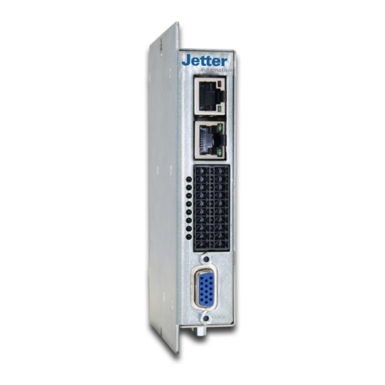
Page 9: Product Description
Jetter AG Product description | 4 4 Product description Fig. 1: Connections Encoder connector Power and motor connector X1 SD card X22 DIP switch S2 Address selector S1, optional Fieldbus interface IN X18 Fieldbus interface OUT X19 I/O interface X10 Encoder connector X62 User Manual –... -
Page 10: Nameplate
Jetter AG Product description | 4 4.1 Nameplate JM-1008-S1A0 Logic Supply: 1*24VDC / 0,3A Power Supply: 1*24-48VDC / 10A Out: 3*17-34VAC / 0-400Hz / 3*8A Part No: 60881662_00 Vx.xxxx 20993548XXXXXX Enclosure Rating: IP20 Ambient Temperature: 0 - 40°C, 32 - 104°F Made in Germany Fig. 2: Nameplate of the servo amplifier... -
Page 11: Type Key
Jetter AG Product description | 4 4.2 Type key The type key consists of the following elements: User Manual – JM-100x-S1 11 / 35... -
Page 12: System Overview
Jetter AG Product description | 4 4.3 System overview JM-100x- JM-100x- JM-100x- S1… S1… S1… Fig. 3: System overview Power connection (X1), (power supply), SELV / PELV, DC 24 V to DC 48 V Control voltage (X10), (logic supply), SELV / PELV, DC 24 V Controller Field bus... -
Page 13: Technical Specifications
Jetter AG Technical specifications | 5 5 Technical specifications This chapter contains information on electrical and mechanical data as well as operating data of the JM-100x. 5.1 Dimensions Fig. 4: Dimensions 5.2 Enclosure properties and operating conditions Enclosure Material Galvanized steel plate... -
Page 14: Environmental Conditions - Storage And Shipment
Jetter AG Technical specifications | 5 5.3 Environmental conditions - Storage and shipment Transport conditions Ambient temperature - 25 °C … +70 °C Air humidity 5 % … 95 %, non-condensing Mechanical conditions 60721-3-2:2018 Storage conditions Ambient temperature - 25 °C … +55 °C Air humidity 5 % …... -
Page 15: I/O Interface X10
Jetter AG Technical specifications | 5 5.5 I/O interface X10 Motor holding brake Connection X10:3, X10:4 Max. output current 500 mA SI inputs and digital 24 V inputs Input voltage Min. Typ. Max. +15 V +24 V +30 V -3 V 0 V +5 V Input current 5 mA Cable length Max. -
Page 16: Fieldbus Interfaces
Jetter AG Technical specifications | 5 Properties Suitable encoders 5 V differential signals (RS-422) with or without reference signal Max. frequency 500 kHz Digital Hall sensors X62 Suitable encoders No restrictions EnDat 2.2 Suitable encoders No restrictions Motor temperature monitoring Digital sensors... -
Page 17: Mechanical Installation
Jetter AG Mechanical installation | 6 6 Mechanical installation This servo amplifier has been designed for being installed in a control cabinet. Die Schutzart ist IP20. The specified ambient conditions during operation must be complied with. The servo amplifier must be fastened to a metal mounting panel in vertical direc- tion with the power and motor connector X1 pointing downwards. -
Page 18: Electrical Installation
Jetter AG Electrical installation | 7 7 Electrical installation 7.1 General remarks The user is responsible for ensuring that the installation of servo amplifier JM-100x, motor, and other devices complies with the safety instructions (e. g. DIN, VDE), as well as with all other relevant federal or local regulations as to di- mensioning of conductors, protection, grounding, breakers, overcurrent protec- tion, etc. -
Page 19: Block Diagram
Jetter AG Electrical installation | 7 7.2 Block diagram JM-100x STO1 Logic supply (X10) X10:5 GND_STO1 X10:6 Power supply for logic X10:1 SELV or circuitry: +24 V SI inputs PELV STO2 Power supply for logic X10:7 (STO) X10:2 circuitry - GND... -
Page 20: Pin Assignment Of Connections
Jetter AG Electrical installation | 7 7.3 Pin assignment of connections 7.3.1 Power and motor connector X1 Signal Function X1:1 Motor connection X1:2 Motor connection X1:3 Motor connection X1:4 Ballast Motor connection or ballast resistor to be connected between this PIN and GND 48 V. - Page 21 Jetter AG Electrical installation | 7 7.3.2 I/O interface X10 The I/O interface includes the following pins: Power supply for logic circuitry, mo- tor holding brake, 2 SI inputs, 1 checkback contact, 4 digital 24 V inputs (not SI), and 2 analog inputs.
- Page 22 Jetter AG Electrical installation | 7 7.3.3 Encoder X61/X62 Position encoders can be connected to X61 and X62. A second encoder which is directly fitted to the mechanical system can be used to detect its position. The following combinations are supported: Motor encoder 2.
- Page 23 Jetter AG Electrical installation | 7 Signal X61:1 n. c. X61:2 n. c. X61:3 DSL+ X61:4 TH+ motor temperature monitoring X61:5 n. c. X61:6 n. c. X61:7 n. c. X61:8 DSL- X61:9 TH-motor temperature monitoring Tab. 3: HIPERFACE DSL® Signal X61:1 n.
- Page 24 Sym does not support the Hall and EnDat digital encoder types for JM-100x. For absolute encoders, please use the TD option (HIPERFACE DSL® 2-wire, Jetter motors with F17 and F18 encoders). For pinout refer to the X61 connector instead of resolver.
- Page 25 Jetter AG Electrical installation | 7 7.3.4 LinMot Motor Cable PRELIMINARY PWR+ PGND 1+ u 1- v 2+ w 2- x SCRN 1* Ph 1+ u 2* Ph 2+ w 3 +5VDC 4 SIN 5 TEMP 6* Ph 1- v...
- Page 26 Jetter AG Electrical installation | 7 When using a PS01 series motor cable, the motor pinout is as follows: PS01-23x80F-HP-R Motor pinout Motor cable wire color PS01-23x80F-HP-R20 R-connector Ph 1+ Ph 1- Pink Ph 2+ Blue Fig. 9: 9-pin male con- Ph 2- Gray nector DC +5 V...
- Page 27 Jetter AG Electrical installation | 7 Fieldbus interface As fieldbus interfaces, 2 RJ45 ports are available. Connector X18, BUS IN, is the CAN input. Connector X19, BUS OUT, lets you connect further fieldbus nodes. The status LED is for diagnostics. Setting the drive address via address selector S1 Address selector S1 is used to configure the drive address.
- Page 28 Jetter AG Electrical installation | 7 The following illustration shows their flashing code. LED BUS RUN Signal Description Pos. Bus node state is STOPPED Communication with SDO or PDO is not possible Bus node state is STOPPED Blinks once Communication with SDO or PDO is not possible...
-
Page 29: Service Interfaces
® JM-1008_X18_X19_EtherCAT_Struktur_0-1.vsd Flashing: Communication with EtherCAT device is active 7.4 Service interfaces The service interfaces are not intended for users. They are reserved for Jetter-in- ternal service purposes. The service interfaces are listed below: ■ RS-232 interface (X20) ■... -
Page 30: Led Indicators
Jetter AG Electrical installation | 7 7.5 LED indicators Enabling visual diagnostics, the servo amplifier is equipped with 8 status LEDs lo- cated vertically to the left of the X10 I/O interface. The LEDs are controlled by the microcontroller. Therefore, the indicated operat- ing states depend on its firmware. -
Page 31: Maintenance And Repairs
Only replacing the servo amplifier as a whole is permitted. 8.4 Return and disposal How to dispose of Return your Jetter AG product to us for proper disposal. Visit our homepage waste equipment detailed information and to download the required Returns form. - Page 32 Jetter AG Maintenance and repairs | 8 Applicable local environmental directives and regulations must be complied with. The product is waste electronic equipment and must be disposed of by a certified waste management facility. Do not dispose of the product with normal household waste.
-
Page 33: Service
The OS is stored to the flash memory in the CPU. This memory cannot be ac- cessed by the user. Important system files, such as firmware, images or EDS, are protected. Jetter AG are continuously striving to enhance the operating systems of their products. Enhancing means adding new features, and upgrading existing func- tions. - Page 34 Jetter AG Index of illustrations Index of illustrations Fig. 1 Connections..........................Fig. 2 Nameplate of the servo amplifier..................... Fig. 3 System overview ........................Fig. 4 Dimensions..........................Fig. 5 Block diagram_JM-100X ......................Fig. 6 X10 pinout ..........................Fig. 7 X61 pinout ..........................
- Page 35 Jetter AG Graeterstrasse 2 71642 Ludwigsburg www.jetter.de E-mail info@jetter.de Phone +49 7141 2550-0 We automate your success.
Need help?
Do you have a question about the JetMove JM-100 S1 Series and is the answer not in the manual?
Questions and answers