
Related Manuals for Jetter JM-203B-230


Summary of Contents for Jetter JM-203B-230
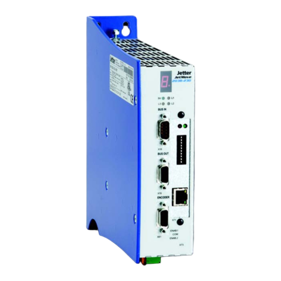
- Page 1 User Manual JM-203B-230 - Digital Servo Amplifier 60865160 We automate your success.
-
Page 2: Application
Item no. 60865160 Revision 3.11 March 2019 / Printed in Germany Jetter AG reserve the right to make alterations to its products in the interest of technical progress. These alterations will not necessarily be documented in every single case. This manual and the information contained herein have been compiled with due diligence. - Page 3 JetMove 203B-230 Introduction How to contact us Jetter AG Graeterstrasse 2 71642 Ludwigsburg Germany Phone - Switchboard: +49 7141 2550-0 Phone - Sales: +49 7141 2550-433 Phone - Technical Hotline: +49 7141 2550-444 Fax - Sales: +49 7141 2550-484 E-mail - Sales: sales@jetter.de...
- Page 4 Missing or inadequate knowledge of the manual results in the loss of any claim of liability on part of Jetter AG. Therefore, the operating company is recommended to have the instruction of the persons concerned confirmed in writing.
- Page 5 Note! · / - Enumerations are marked by full stops, strokes or scores. Operating instructions are marked by this arrow. Automatically running processes or results to be achieved are marked by this arrow. Jetter AG...
- Page 6 Introduction Reference to PC keyboard and HMI keys. This symbol informs you of additional references (data sheets, literature, etc.) associated with the given subject, product, etc. It also helps you to find your way around this manual. Jetter AG...
-
Page 7: Table Of Contents
Notes on decommissioning Operating conditions Physical dimensions Technical data Electrical specifications Motor protection 5.2.1 Thermal sensor integrated in the motor 5.2.2 I²t calculation 5.2.3 Motor overload protection according to UL Drive controller structure Description of connections Power supply connection Jetter AG... - Page 8 Sin-cos encoder connection 7.5.1 Adapter 7.5.2 Specification 7.5.3 Connection diagram Digital inputs, logic power supply Jetter system bus 7.7.1 Specifications of the Jetter system bus cable Status monitoring Diagnostics Error messages WARNINGS Connection diagrams Analog input (option) 11.1 Operating principle 11.2 Technical data 11.3...
- Page 9 Requirements placed on the safety system 13.5.1 Control variants for "Safe Standstill" 13.5.2 Application 1 13.5.3 Application 2 13.5.4 Application 3 13.5.5 Application 4 13.6 Block diagram of the JM-203B-230 with the "Safe Standstill" function Counting input (option) 14.1 Operating principle 14.2 EnDat 2.2 14.2.1 Technical data...
- Page 10 Table of Contents 203B-230 Appendix C: Glossary Appendix D: Index of illustrations Appendix E: Index Jetter AG...
-
Page 11: Safety Instructions
Do not apply the integrated brake control in safety-relevant systems. The servo amplifier JetMove 203B-230 is not a safety-relevant device according to the machinery directive 2006/42/EG. Therefore, using this servo amplifier for safety-relevant applications as regards safety of persons is neither adequate nor permitted. Jetter AG... -
Page 12: Qualified Personnel
The installation of such parts may impair the safety and the proper functioning of the digital servo amplifier JetMove 203B-230. Any liability on the part of Jetter AG for any damages resulting from the use of non- original parts and equipment is excluded. -
Page 13: Repair And Maintenance
The servo amplifier JetMove 203B-230 does not contain any parts to be repaired by the operator. For being repaired, the servo amplifier JetMove 203B-230 must be sent to Jetter AG. The digital servo amplifier JetMove203B-230 is maintenance-free. Therefore, absolutely no inspection or maintenance works are required for the operation of this device. -
Page 14: Ensure Your Own Safety
Secure the servo amplifier JetMove 203B-230 against misuse or accidental use. 1.2.2 Information signs and labels Follow the instructions given on markings, information signs, and labels. Keep markings, signs and labels readable. Replace damaged or unreadable information signs and labels. Jetter AG... -
Page 15: Earthing Procedure
A durable connection with the power supply of the digital servo amplifier JetMove 203B-230 has to be provided. • Correct cabling of the PE bus according to the connection diagram must be carried out, chapter 10 "Connection diagrams", page 77. Jetter AG... - Page 16 If, in spite of this, an earth-leakage current breaker is installed, it will switch off the digital servo amplifier JetMove 203B-230, although there is no fault. When a leakage current screen needs to be installed in the JetMove 203B-230, an isolating transformer must be used. Jetter AG...
-
Page 17: Residual Dangers
Never touch the left sidewall of the servo amplifier JetMove D203 during operation and after switching off, while the device is still cooling down. Make sure that no temperature-sensitive parts have been connected or fastened to the servo amplifier JetMove 203B-230. Jetter AG... - Page 18 Make sure that hazards to persons are precluded even when the drive is rotating unintentionally. Do not remove any guards. Do not wear gloves, lest they should get caught in the rotating drive shaft. Never touch a rotating drive shaft. Warning Jetter AG...
-
Page 19: Hazards After Power Is Turned Off
Always wait at least ten minutes after switching off, before taking the following actions: – Touching the screws of the terminals X1 and X62 – Disconnecting the terminals and touching the contacts Jetter AG... -
Page 20: Instructions On Emi
Follow the instructions given in Application Note 016 "EMC-Compatible Installation of theElectric Cabinet" published by Jetter AG. The following instructions are excerpts from Application Note 016: Screw the enclosure of the digital servo amplifier JetMove 203B-230 onto a highly conducting, earthed panel. - Page 21 Only use metallized connectors, e.g. Sub-D with metallized housing. Make sure that the strain relief is directly connected with the housing here as well (see fig. 2). Fig.: 2: Shielding of Sub-D connectors in conformity with EMC standards Jetter AG...
- Page 22 We recommend installing the enclosed ferrite core on the motor power supply cable as shown in figure 3. For optimum results, increase the number of turns around the ferrite. Fig.: 3: Shielding of screw terminals in conformity with the EMC standards Jetter AG...
-
Page 23: Jetmove 203B-230 - Installation Instructions
Resolver cable, see chapter 7.3 "Resolver connection", page 55. • HIPERFACE cable, see chapter 7.4 "HIPERFACE connection", page 57. • Synchronous servo motors, e. g. the Jetter motor types JL, JK, or JH • Motor circuit braker, see chapter 5 "Technical data", page 37. •... -
Page 24: Mechanical Installation
Drill the holes and cut the respective threads into the panel. Screw the corresponding fitting bolts into the thread by approximately half of their length. By means of the oblong holes in the rear plate, hang up the JetMove 203B-230 by the fitting bolts; then screw them tightly. Jetter AG... - Page 25 JetMove 203B-230 2.2 Mechanical installation 11.5 29.5 r = 2.8 r = 4.8 r = 2.8 Fig.: 4: Rear and front view of the JetMove 203B-230 enclosure with mounting holes Jetter AG...
-
Page 26: Electrical Installation
Observe the max. tightening torque, see appendex F. To connect resolvers or power units you can use prefabricated cables available from Jetter or opt for self-made cables. Please refer to chapter 7 "Description of connections", page 47. Please regard the following items regarding installation according to EMC: –... -
Page 27: Checking The Installation
Please take into account the information on residual dangers given in chapter 1.3.2 "Hazards after POWER is turned OFF", page 19. Before carrying out installation and maintenance jobs, separate the servo amplifier JetMove 203B-230 and all connected devices from the mains (pull out the mains plug). Jetter AG... -
Page 28: Notes On Safety As Regards Commissioning
For this, the measures listed in chapter 1.2.3 "Earthing procedure", page 15 have to be taken. Always carry out each commissioning, even a short functional test, with correctly connected PE bus. Jetter AG... -
Page 29: Notes On Decommissioning
JetMove 203B-230 2.7 Notes on decommissioning Notes on decommissioning Before returning the device, remove the cable strap serving as strain relief and motor cable shield. Jetter AG... - Page 30 2 JetMove 203B-230 - Installation instructions Jetter AG...
-
Page 31: Operating Conditions
Operating altitude Up to 1,000 m above sea level DIN EN 50178 1,000 to 2,500 m above sea level with derating of 1.5 % per 100 m Jetter AG... -
Page 32: Operating Parameters
Measures to avoid damages in transit and storage: The packaging material and the storage place are to be chosen in a way that the values given in the above table "Operating parameters" on page 31 are kept to. Jetter AG... - Page 33 Frequency band 80 ... DIN EN 61000-4-3 modulated 1,000 MHz; test field strength DIN EN 61800-3 10 V/m AM 80 % at 1 kHz Criterion A Contact discharge: DIN EN 61800-3 Test peak voltage 6 kV DIN EN 61000-4-2 Criterion B Jetter AG...
- Page 34 Test voltage 10 V DIN EN 61000-4-6 AM 80 % at 1 kHz Criterion A Burst (fast transients) Test voltage 1 kV DIN EN 61800-3 tr/tn 5/50 ns DIN EN 61000-4-4 Repetition frequency 5 kHz Criterion B Jetter AG...
-
Page 35: Physical Dimensions
JetMove 203B-230 Physical dimensions 29.5 11.5 Fig.: 5: Physical dimensions of the JetMove 203B-230 (in mm) For installation, please also refer to fig. 4 on page 25. Jetter AG... - Page 36 4 Physical dimensions Jetter AG...
-
Page 37: Technical Data
Motor output current at an ambient Nominal current: I = 3 A temperature of 45 °C Peak current for 30 seconds min.: I = 6 A (The duration depends on the temperature of the heat sink) See "Note 2!" on page 39. Jetter AG... - Page 38 > 60 °C Max. length of the motor cable 50 m max. (for greater lengths please contact Jetter AG) Line filter Line filter ensuring EMC in a residential environment to DIN EN 61800-3 with no limitations. The following filters can be applied with input circuits: –...
- Page 39 Note 3! A line filter can supply several digital servo amplifiers JetMove 203B-230, as soon as I (the current of the line filter) is greater than the total current of the connected servo amplifiers. Jetter AG...
- Page 40 1.2.3 "Earthing procedure", page 15. Warning Compatible synchronous servo motors Motor types Jetter motor types JL, JK and JH Please refer to "Jetter Motor Catalog" or contact the sales department of Jetter AG. Note! In case you intend to use motors other than the above mentioned types, please contact Jetter AG.
-
Page 41: Motor Protection
The digital servo amplifier JetMove 203B-230 calculates the percentage of motor power loss according to the following formula: – -- - average motor current x t ( ) × × 100% ---------------------------------------------------- - – rated current Jetter AG... -
Page 42: Motor Overload Protection According To Ul
20 seconds. This protection (error message 31 is activated) can be parameterized only through the rated current value. The motor overload protection is always active and cannot be deactivated. Jetter AG... - Page 43 Because of the fact that after reset the motor overload calculation always starts with zero, the result is wrong if the motor is already hot when the digital servo amplifier JetMove 203B-230 is switched on (i. e. at the time of connecting the 24 V logic power supply). Important Jetter AG...
- Page 44 5 Technical data Jetter AG...
-
Page 45: Drive Controller Structure
JetMove 203B-230 Drive controller structure Fig.: 6: Block diagram of drive controller structure Jetter AG... - Page 46 12 bits per revolution – Scan time 62.5 µs Absolute encoder (Multiturn and Single-Turn): – Interface HIPERFACE – Resolution of absolute position 15 bits per revolution – Resolution of velocity pickup 20 bits per revolution – Scan time 62.5 µs Jetter AG...
-
Page 47: Description Of Connections
/ green core 1 mains phase 1 core 2 mains phase 2 core 3 mains phase 3 Autotransformer or Fuse or isolating overcurrent transformer circuit breaker or motor current circuit breaker Fig.: 7: Connection of the 3-phase supply line Jetter AG... - Page 48 AC 230 V between mains phase and neutral conductor PE conductor yellow / green core 2 neutral core 3 mains phase Fuse or overcurrent circuit breaker or motor current circuit breaker Fig.: 8: Connection of the 1-phase supply line Jetter AG...
-
Page 49: Motor Connection
Important! Measures to avoid oscillation and blocking of the motor: Avoid mixing-up of phase cables, resp. be sure to connect the phase cables according to pin assignment. Jetter AG... -
Page 50: Assignment And Specifications
Connection of the brake is optional. Important Note ! 24 V A free-wheeling diode is necessary in case it has not been integrated in the motor yet. In Jetter motors, free-wheeling diodes have not been integrated! Recommended The shield is extensively diode type: 1N4002... -
Page 51: Motor Power Cable With Mating Connector Sc
Motor power cable with mating connector SC (female connector) suitable for the Jetter motor types JL2, JL3, JL4, JK4, JK5, JK6 can be ordered from Jetter AG. It is confectioned with the matching motor mating connector and can be ordered by... - Page 52 SC for JetMove 203B-230 For connection without motor holding brake Motor power cable, cable assy no. 26.1 Field wiring terminals Shielding Motor mating of the JM-203B-230 connector (female, solder side) (4 x 1.5 mm (2 x Highly flexible 1.5 mm...
- Page 53 JetMove 203B-230 7.2 Motor connection For connection with motor holding brake Motor power cable, cable assy no. 24.1 Field wiring terminals Shielding Mating of the JM-203B-230 connector of the motor (female, solder side) (4 x 1.5 mm (2 x Highly flexible 1.5 mm...
-
Page 54: Connection Assignment Of Terminal Box
Motor terminal box - terminal assignment of the amplifier X62.U2 Pin 1 Phase 1 X62.V2 Pin 2 Phase 2 X62.W2 Pin 3 Phase 3 X62.PE Pin 4 Protective earth X10.BRAKE2 Pin 7 Brake + X10.GND Pin 8 Brake - alternative to motor connectors Jetter AG... -
Page 55: Resolver Connection
Resolver/HIPERFACE The complete resolver cable between the servo amplifier series JetMove 2xx and the Jetter motor types JL, JK and JH can be obtained from Jetter AG. It can be ordered by supplying the following cable assy number: Cable assy no. 23... - Page 56 Cosine - blue Sine - amber Sine + green R1R (exciter pink winding +) R2L (exciter gray winding -) white (Thermal sensor) brown (Thermal sensor) Unassigned 9 - 12 Dimensions of the resolver mating connector are specified in millimeters. Jetter AG...
-
Page 57: Hiperface Connection
7.4.2 HIPERFACE cable with mating connector Note! The resolver respectively HIPERFACE mating connector of the Jetter motor types JL, JK and JH can be ordered from Jetter AG by supplying the following particulars: Item no. 15100069 Resolver/HIPERFACE The complete HIPERFACE cable connecting the servo amplifier series JetMove 2xx and the Jetter motor types JL, JK and JH can be obtained from Jetter AG. - Page 58 7 Description of connections HIPERFACE mating connector (solder side) Solder 10 2 Side Fig.: 12: RC series HIPERFACE mating connector (internal thread M23) Jetter AG...
- Page 59 DATA - (RS-485) gray DATA + (RS-485) pink blue Power supply (7 through 12 volts) Thermal sensor black Thermal sensor Pin 9 and pin 12 are short-circuited. Dimensions of the HIPERFACE mating connector are specified in millimeters. Jetter AG...
-
Page 60: Sin-Cos Encoder Connection
7.5.1 Adapter An adapter is needed for connecting a sin-cos encoder. This adapter can be obtained from Jetter AG by the following specification: JM-200-ENC-ADAP (item no. 10000430) Another 9-pin SUB-D connector of the encoder cable can be connected to this adapter. -
Page 61: Connection Diagram
7.5 Sin-cos encoder connection 7.5.3 Connection diagram JM-200-ENC-ADAP Sin-cos encoder +5 V +5 V Sin+ Sin+ ENCODER Cos+ Cos+ Index+ Index+ Sin- Sin- Cos- Cos- Index- Index- JetMove Motor temp sensor Fig.: 13: Sin-cos encoder connection with adapter Jetter AG... - Page 62 Connect shield with the greatest possible surface have a metric thread! area! Use metallized housing only! Signal Sine + Reference sine Cosine + Reference cosine Index + Reference index Power supply (5 V - 100 mA max.) Unassigned Jetter AG...
- Page 63 If necessary, the encoder supply cords have to have a greater diameter. If a motor temperature sensor is not used, the inputs have to be short- circuited at the adapter, so the JetMove 2xx will not give an error message. Jetter AG...
-
Page 64: Digital Inputs, Logic Power Supply
Depending on the • DC 24 V limit switch parameter setting, this • 7.5 mA max. (input) input is used as a • Operating negative limit switch. point: < 6 V low, > 15 V high NC or NO contact Jetter AG... - Page 65 In Jetter motors, free- wheeling diodes have not been integrated! Recommended diode type: 1N4002 *) is connected to the ground of the control system.
-
Page 66: Jetter System Bus
7 Description of connections Jetter system bus By means of the Jetter system bus, the JetMove 203B-230 is interlinked with the controller, additional JetMove amplifiers, or Jetter peripheral modules. The system bus input BUS-IN is a 9-pin Sub-D male connector, and the system bus output BUS- OUT is a 9-pin Sub-D female connector. - Page 67 JetMove 203B-230 7.7 Jetter system bus Allowed cable lengths Baud rate Max. cable Max. tap line Max. overall tap length length line length 1 MBaud 30 m 0.3 m 500 kBaud 100 m 39 m 250 kBaud 200 m 78 m...
- Page 68 7 Description of connections Jetter AG...
-
Page 69: Status Monitoring
The drive controller can be switched READY TO BE SWITCHED Drive controller has been disabled by software command. The drive controller can be switched SWITCHED ON DC link monitoring is activated. OPERATION_ENABLED The drive controller has been enabled. Jetter AG... - Page 70 M < 0, n < 0 --> Quadrant III Mode of operation - Motor M > 0, n < 0 --> Quadrant IV Mode of operation - Generator Positive current limit has been reached. Negative current limit has been reached. Jetter AG...
-
Page 71: Diagnostics
A DC link voltage of – Immediate – Check input voltage DC link > 480 V has been motor power supply. detected. disable – If the motor is used as generator, reduce the regenerating power. – Acknowledge failure. Jetter AG... - Page 72 – Acknowledge failure. F 11 Current overrange A current – Immediate – Reduce K of the temporarily too high motor power current controller by has been detected. disable 10 to 20 %. – Acknowledge failure. Jetter AG...
- Page 73 – Check reference and a software limit position. switch has tripped. – Acknowledge failure. – Return the axis to a position within the software travel limits (monitoring of software limit switches is re- enabled automatically at entering this range). Jetter AG...
- Page 74 – Acknowledge failure. F 24 Error in 24 V The external 24 V – Immediate – Check external (combined supply voltage supply was lower motor power power supply. with F 01) than 18 V. disable – Acknowledge failure. Jetter AG...
- Page 75 – Acknowledge failure. results being guaranteed. F 42 Malfunctioning of Encoder breakage – Immediate – Check the encoder encoder 2 (only for or initialization error motor power line and all plug-in the option CNT) disable connections. – Acknowledge failure. Jetter AG...
-
Page 76: Warnings
9 Diagnostics WARNINGS If the dot in the seven-segment display is flashing, one or several warnings have been recognized. Check in the Motion Setup or by issuing the motion instructions in the controller program which warning is active. Jetter AG... -
Page 77: Connection Diagrams
Ferrite core Note! A free-wheeling diode is needed, if it has not been L1’ L2' integrated in the motor. Filter In Jetter motors, free- wheeling diodes have been integrated! Recommended diode type: 24 V 1N4002 Contactor Fig.: 14: Connection diagram JetMove 203B-230, 1-phase connection, type of position transducer: Resolver See also chapter 7 "Description of connections", page 47. - Page 78 Note! A free-wheeling diode is needed, if it has not been L1’ L2' integrated in the motor. Filter In Jetter motors, free- wheeling diodes have been integrated! Recommended diode type: 24 V 1N4002 Contactor Fig.: 15: Connection diagram JetMove 203B-230, 1-phase connection, type of...
- Page 79 Note! A free-wheeling diode is needed, if it has not been L1’ L2' L3’ integrated in the motor. Filter In Jetter motors, free- wheeling diodes have been integrated! Recommended diode type: 24 V 1N4002 Contactor Fig.: 16: Connection diagram JetMove 203B-230, 3-phase connection, type of...
- Page 80 Note! A free-wheeling diode is needed, if it has not been L1’ L2' L3’ integrated in the motor. Filter In Jetter motors, free- wheeling diodes have been integrated! Recommended diode type: 24 V 1N4002 Contactor Fig.: 17: Connection diagram JetMove 203B-230, 3-phase connection, type of...
- Page 81 Key to the wiring diagrams: Line filter (optional) (refer to "Line filter" on page 38) Mains protection (refer to "Overload protection" on page 37) Motor Motor holding brake (option) Position transducer (resolver or HIPERFACE encoder) Motor overtemperature protection Isolating transformer or autotransformer Jetter AG...
- Page 82 10 Connection diagrams Jetter AG...
-
Page 83: Analog Input (Option)
Operating principle For the digital servo amplifier JetMove 203B-230, an optional integrated analog input card can be ordered (article designation of the device: JM-203B-230...-IA1). This card supplies an analog input of a 12-bit resolution. The converted value of the measured voltage can be read by a register of the JetMove in the PLC program or processed by the firmware of the JetMove in an additional controller. -
Page 84: Description Of Connections
Connect shield with the greatest possible surface area! Use metallized housing only! Signal Analog signal (0 - 10 V to pin 6) 6 - 9 Analog GND (connected to earth in the device) 2 - 5 Do not use Jetter AG... -
Page 85: Ethernet Interface (Option)
Operating principle For the digital servo amplifier JetMove 203B-230, an optional integrated Ethernet interface can be ordered (article designation of the device: JM-203B-230...-OEM). This allows for the JetMove 203B-230 to be addressed by the controller via Ethernet instead of the Jetter system bus. -
Page 86: Connection Between The Jetmove 203B-230
• JetControl to PC • JetControl to JetMove...-OEM • etc. Note! Terminals with infrastructure components (e.g. switch) have to be interconnected via straight-through cables: • PC to switch • JetControl to switch • JetMove...-OEM to switch • etc. Jetter AG... -
Page 87: Logic Circuit Leds, Switches
The boot loader is running. There is no valid operating system of the Ethernet interface available. The red LED (ERR) and the green LED Fatal operating system error of the (RUN) are flashing alternately with Ethernet interface intermittent breaks during runtime. Jetter AG... -
Page 88: The Dip Switches
If, at activating the JetMove 203B-230...-OEM, the DIP switches 1 through 8 are in "ON" position, the JetControl has got the IP address saved in the configuration memory. The configuration memory can be accessed by means of the "/System/cfgvar.ini" file or registers 10131 through 10145. Jetter AG... - Page 89 Saving the configuration values 10131 Version number 10132 IP address MSB 10133 IP address 3SB 10134 IP address 2SB 10135 IP address LSB 10136 Subnet mask MSB 10137 Subnet mask 3SB 10138 Subnet mask 2SB 10139 Subnet mask LSB Jetter AG...
-
Page 90: Ip Address Taken From The Switch Position
8. To make up the IP address, the position of DIP switches 1 through 8 is read in once during the start-up procedure. The actual settings of DIP switches 1 through 8 can be scanned from register 10180. Jetter AG... -
Page 91: Safe Standstill (Option)
Safe Standstill (option) For the digital servo amplifier JetMove 203B-230 an optional integrated card for the "Safe Standstill" and "Safe Restart Inhibit" function can be ordered (designation of the device: JM-203B-230...-S1). 13.1 Introduction The option "Safe Standstill" serves for safe de-energizing the motor, if personal or material damage caused by a moving or inadvertently started motor is to be reliably prevented. -
Page 92: Motion System Jm-203B-230-S1
13 Safe Standstill (option) 13.2 Motion system JM-203B-230-S1 The following figure is to demonstrate the basic setting of a motion system using a digital servo amplifier JetMove 203B-230-S1 equipped with the "Safe Standstill" function. Input Safety “Safe Standstill” device JM-(D)2xx Mech. -
Page 93: Safety Instructions
6. Re-enable the same axis. If the torque cannot be checked, drive the axis. 7. Interrupt the circuit of the Enable2 input at encoder terminal X73; the axis must be de-energized (no torque), respectively stop rotating, immediately. 8. Re-activate the Enable2 input at terminal X73; clear faults within the servo amplifier. Jetter AG... -
Page 94: Requirements Placed On The Safety System
Within the framework of this classification, the CCF ("Common Cause Failure") referred to in the standard mainly applies to the related application. Here we proceed from the assumption that the measures taken by R&D and application departments will ensure that the required score is achieved. Jetter AG... - Page 95 Basically, the following measures make sure that servo amplifiers of the JetMove 2xx avoid Common Cause Failures. • Electrical isolation (optocoupler) from power supply units • Compliance with clearances and creepage distances (layout and wiring) • Overrating of components and derating Jetter AG...
-
Page 96: Control Variants For "Safe Standstill
24 V < 1.3 ms > 7.0 ms Fig.: 20: Example: OSSD signal waveform, single pulse 24 V < 0.8 ms 0.5 ms < 0.8 ms > 7.0 ms Fig.: 21: Example: OSSD signal waveform, dual pulse Jetter AG... -
Page 97: Application
Following this example, "Safe Standstill" (according to EN 954-1 Category 1) with Stop Category 0 (according to EN 60204) can be implemented, if all safety switching devices involved meet the requirements of Category 1. Jetter AG... -
Page 98: Application 2
These tests are to prove freedom from faults of the entire system. Following this example, "Safe Standstill" (according to EN 954-1 Category 2) with Stop Category 0 (according to EN 60204) can be implemented, if all safety switching devices involved meet the requirements of Category 2. Jetter AG... -
Page 99: Application
Following this example, "Safe Standstill" (according to EN 954-1 Category 3) with Stop Category 0 (according to EN 60204) can be implemented, if all safety switching devices involved meet the requirements of Category 3. Jetter AG... -
Page 100: Application
Following this example, "Safe Standstill" (according to EN 954-1 Category 1) with Stop Category 1 (according to EN 60204) can be implemented, if all safety switching devices involved meet the requirements of Category 1. Yet, the Safely-Limited Acceleration (SLA) is not met. Jetter AG... -
Page 101: Block Diagram Of The Jm-203B-230 With The "Safe Standstill Function
JetMove 203B-230 13 Safe Standstill (option) 13.6 Block diagram of the JM-203B-230 with the "Safe Standstill" function In the following figure, the most important components of the digital servo amplifier JetMove 203B-230 with the option -S1 ("Safe Standstill") are illustrated:... - Page 102 10E-14 per hour (several million years). Out of these, only 6 out of 15 cases lead to jerking. This means that practically, there is no possibility of this to happen. Moreover, the IGBTs are continually being checked at each commutation. Jetter AG...
-
Page 103: Counting Input (Option)
14.1 Operating principle For the digital servo amplifier JetMove 203B-230, an optional integrated analog counting card can be ordered (article designation of the device: JM-203B-230...- CNT). It supplies a counting input equipped with the following interface: • EnDat 2.2 by Heidenhain •... -
Page 104: Description Of Connections
Resolver/HIPERFACE The complete HIPERFACE cable between the servo amplifier types JetMove 2xx and the Jetter motor types JL, JK, and JH can be ordered from Jetter AG. It can be ordered by submitting the following cable specifications and the respective... - Page 105 Clock - (RS-485) gray Clock + (RS-485) pink blue 5 V power supply 200 mA max. Unassigned black Unassigned Pin 9 and pin 12 are short-circuited (thermal sensor HIPERFACE) The measurements of the EnDat mating connector are specified in millimeters. Jetter AG...
-
Page 106: Power Supply Of The Encoder
, there results a maximum cable length of or - at a cable length of 80 m - the following cross section is needed: 54.74 m A=0.5 mm By a double wiring arrangement, the cable length can be doubled. Jetter AG... -
Page 107: Synchronous Serial Interface (Ssi)
• Material: Copper • Temperature class: 60 °C • Maximum cable length: 100 m Dependent on the encoder type, the transmission frequency has to be reduced due to the signal runtimes in long cables. Jetter AG... -
Page 108: Ssi Cable
Connect shield with the have a metric thread! greatest possible surface area! Use metallized housing only! Signal Clock + DATA + do not use Power supply 5 V, 200 mA max. Clock - DATA - do not use do not use Jetter AG... -
Page 109: Incremental Encoder
0 V and power supply • The shield must be connected to the connector housings on both ends of the cable with the greatest possible surface area. • Material: Copper • Temperature class: 60 °C • Maximum cable length: 100 m Jetter AG... -
Page 110: Incremental Encoder Cable
Connect shield with the have a metric thread! greatest possible surface area! Use metallized housing only! Signal K0 + K1 + K2 + Power supply 5 V, 200 mA max. K0 - K1 - K2 - do not use Jetter AG... -
Page 111: Ordering Information
JetMove 203B-230 15 Ordering information Ordering information 15.1 List of documentation The documents listed below have been supplied on the website of Jetter AG at http:/ /www.jetter.de/Support for download. Programming jetmove_2xx_D203_at_the_jetcontrol_bi_xxxx_user_information.pdf User information on configuration and operation of the JetMove2xx series at the JetControl 24x Item no. - Page 112 15 Ordering information Jetter AG...
- Page 113 JetMove 203B-230 Appendices Appendices Jetter AG...
- Page 114 Appendices Jetter AG...
-
Page 115: Appendix A: Recent Revisions
Appendix A: Recent revisions appendices List Chapter Remarks Revised Added Deleted Reference to Package Insert 2 X71 instead of X72 X71 instead of X72 Appendix F Package Insert 2: Max. tightening torque 3 Nm Jetter AG... -
Page 116: Appendix B: Differences Between Jetmove 203-230 And
500 W, the crucial fusing value (and accordingly the cable size of the power line) has to be increased from 4 A to 10 A. Operating from a 3-phase power supply, there will be no differences. Jetter AG... - Page 117 Cat. 4 to EN 954-1, respectively to PL "e" to ISO 13849-1. The servo amplifier JM-203B-230 can only be operated with OS version 2.11.0.0 or higher. When older versions are used, the servo amplifier will issue an error message.
- Page 118 Appendices Jetter AG...
-
Page 119: Appendix C: Glossary
International Electrotechnical Commission International Protection JetMove JetMove is the type designation of a digital servo amplifier series produced by Jetter AG. The extension 203B-230, for example, marks the following features: – 203 identifies a rated current of 3 A. – 230 identifies the operating voltage of the rated power supply. - Page 120 Appendices Jetter system bus The Jetter system bus is a system-bus system of a cable length of 200 m max. and of fast data transmission rates of 1 MBit/s max. In addition to this, the Jetter system bus is highly immune to interferences.
- Page 121 Milliampere (1 mA = 10 Decibel Gram Hour Hertz Kelvin Meter Centimeter (1 cm = 10 Millimeter (1 mm = 10 Second Volt µV Microvolt (1 µV = 10 Watt Ω °C Degrees centigrade (temperature unit) ° Degrees (angular dimension) Jetter AG...
-
Page 122: Appendix D: Index Of Illustrations
Fig. 25: Application 4 Fig. 26: Block diagram JetMove 203B-230 with the "Safe Standstill" function Fig. 27: Possible rotation angle in case of defective IGBTs Fig. 28: View on RC series mating connector of the EnDat (internal thread M23) Jetter AG... -
Page 123: Appendix E: Index
Leakage current Diagnostics LEDs of the Ethernet interface Dielectric test voltage Line filter Differences between JetMove 203-230 and JetMove 203B-230 Dimensions DIP switches Maintenance Disposal Malfunctions Drive controller specification Modifications Motor braking circuit A free-wheeling diode is required! Jetter AG... - Page 124 Cable assy no. 530 Specification Password Configuration memory Technical data Physical dimensions Terminal box of the motor Pollution degree PWM frequency Usage other than intended Qualified personnel Vibration resistance Reference input Reference variables Warnings Repair Wiring diagrams Residual dangers Jetter AG...
- Page 125 JM-2xx - Package Insert 2 Customer information Jetter AG will provide you with the following important installation instructions for the tightening torque so that the PE bolt (1) does not become loose or even break off. Maximum tightening The nut of the PE bolt (1) may only be tightened up to a maximum tightening torque torque of 3 Nm.
- Page 126 Jetter AG Graeterstrasse 2 71642 Ludwigsburg | Germany Phone +49 7141 2550-0 Fax +49 7141 2550-425 info@jetter.de www.jetter.de We automate your success.
Need help?
Do you have a question about the JM-203B-230 and is the answer not in the manual?
Questions and answers