
Subscribe to Our Youtube Channel
Related Manuals for Hitachi RCI


Summary of Contents for Hitachi RCI
- Page 1 INDOOR UNITS SYSTEM FREE SERIES & Complementary Systems FSN2(M)(E) Service Manual RCIM RPIM RPFI Econofresh...
- Page 3 Index I n d e x General information Unit installation Piping work and refrigerant charge Electrical wiring Control system Optional functions Test run Troubleshooting Spare parts Servicing Electrical checks of the main parts Maintenance notes SMGB0063 rev. 1 - 10/2010...
- Page 4 Index SMGB0063 rev. 1 - 10/2010...
-
Page 5: Table Of Contents
KPI energy / heat recovery unit classification................1.3.3 Product guide: indoor units......................1.3.4 Product guide: complementary systems..................1.3.5 Accessory code list........................Unit installation....................13 RCI - 4-way cassette........................2.1.1 Accessories supplied with the unit....................2.1.2 Unit installation..........................2.1.3 Accessories supplied with the air panel..................2.1.4 Air panel installation........................ - Page 6 Flared connection mounting......................3.4.8 Refrigerant gas pipe insulation....................3.4.9 Refrigerant pipe suspension....................... Refrigerant and drain hose installation..................3.5.1 RCI - 4-way cassette (1.0-6.0)FSN2E..................3.5.2 RCIM-4-way cassette (compact) (1.0-2.0)FSN2................. 3.5.3 RCD - 2-way cassette (1.0-5.0)FSN2..................3.5.4 RPC - Ceiling type (2.0-6.0)FSN2E....................
- Page 7 Wiring diagrams for complementary systems................155 Control system....................159 Device control system........................ 160 5.1.1 Printed circuit boards for RCI(M) indoor units................161 5.1.2 Printed circuit boards for RCD indoor units................. 163 5.1.3 Printed circuit board for RPC, RPF(I), RPI(M) units..............166 5.1.4...
- Page 8 RPK-(2.5-4.0)FSN2E........................258 9.11 RPF-(1.0-2.5)FSN2E........................260 9.12 RPFI-(1.0-2.5)FSN2E......................... 262 Servicing......................265 10.1 RCI - 4-way cassette (1.0-6.0)FSN2E..................268 10.1.1 Removal of the long-lasting air filter.................... 268 10.1.2 Removal of the air inlet grille....................... 268 10.1.3 Removal of the electrical box cover.................... 269 10.1.4...
- Page 9 Index 10.1.11 Removal of the thermistors from the liquid and gas pipes............274 10.1.12 Removal of the electronic expansion valve coil................275 10.1.13 Removal of the automatic louver motor..................276 10.2 RCIM - 4-way cassette (1.0-2.0)FSN2 (compact)..............277 10.2.1 Removal of the air filter....................... 277 10.2.2 Removal of the air inlet grille.......................
- Page 10 Index 10.6.4 Removal of the fan parts......................313 10.6.5 Removal of the float switch......................314 10.6.6 Removal of the air filter....................... 315 10.7 RPC - Ceiling..........................316 10.7.1 Removal of the air filter....................... 316 10.7.2 Removal of the side panel......................316 10.7.3 Removal of the air outlet grille....................
- Page 11 Index 11.2 Electronic expansion valve......................361 11.3 Automatic louver mechanism..................... 362 11.3.1 RCI(M) indoor units........................362 11.3.2 RCD indoor units......................... 363 11.3.3 RPC indoor units......................... 363 Maintenance notes..................365 12.1 Regular equipment maintenance....................366 12.1.1 Regular equipment maintenance....................366 12.1.2 Indoor heat exchanger cleaning....................
- Page 12 Index SMGB0063 rev. 1 - 10/2010...
-
Page 13: General Information
1 General information . G e n e r a l i n f o r m a t i o n Index General information........................1.1.1 Copyright............................1.1.2 Introduction........................... 1.1.3 Environment-friendly units......................Safety............................1.2.1 Symbols used..........................Product guide..........................1.3.1 Classification of indoor unit models....................1.3.2 KPI energy / heat recovery unit classification................ -
Page 14: General Information
No type of modification must be made to the equipment without prior, written authorisation from the manufacturer. 1.1.2 Introduction HITACHI offers the SYSTEM FREE series range of indoor units, the main advantage of which is that they can be combined with UTOPIA and SET FREE series outdoor units. -
Page 15: Environment-Friendly Units
1 General information 1.1.3 Environment-friendly units The new range of HITACHI indoor units uses environment-friendly R410A gas refrigerant and applies RoHS and Green Dot standards throughout the production and installation process to reflect HITACHI's awareness of environmental respect and commitment. -
Page 16: Safety
1 General information 1.2 Safety 1.2.1 Symbols used During normal air conditioning system design work or unit installation, greater attention must be paid in certain situations requiring particular care in order to avoid damage to the unit, the installation or the building or property. Situations that jeopardise the safety of those in the surrounding area or that put the unit itself at risk will be clearly indicated in this manual. -
Page 17: Product Guide
1 General information 1.3 Product guide 1.3.1 Classification of indoor unit models Unit type (indoor unit): RCI, RCIM, RCD, RPC, RPI, RPIM, RPK, RPF, RPFI Position-separating hyphen (fixed) Capacity (HP): 0.8, 1, 1.5, 2, 2.5, 3, 4, 5, 6, 8, 10... -
Page 18: Product Guide: Indoor Units
Check the exact classification for each unit (model, type, power and series) in Classification of indoor unit models, see on page 5. • The RCI, RCIM and RCD models must be used in combination with the panels indicated above. SMGB0063 rev. 1 - 10/2010... - Page 19 1 General information ¿ RPC, RPI and RPIM indoor units FSN2(E/M) indoor units RPIM Ceiling type Indoor ducted unit Unit Code Unit Code Unit Code Unit Code RPIM-0.8FSN2E 7E430000 RPI-0.8FSN2E 7E420000 RPIM-0.8FSN2E -DU 7E431000 RPIM-1.0FSN2E 7E430001 RPI-1.0FSN2E 7E420001 RPIM-1.0FSN2E -DU 7E431001 RPIM-1.5FSN2E 7E430002...
- Page 20 1 General information ¿ RPK, RPF and RPFI indoor units FSN2E indoor units RPFI Wall type Floor type Floor concealed type Unit Code Unit Code Unit Code RPK-1.0FSN2M 60277941 RPF-1.0FSN2E 7E450001 RPFI-1.0FSN2E 7E460001 RPK-1.0FSNH2M 60277961 RPK-1.5FSN2M 60277942 RPF-1.5FSN2E 7E450002 RPFI-1.5FSN2E 7E460002 RPK-1.5FSNH2M 60277962...
-
Page 21: Product Guide: Complementary Systems
1 General information 1.3.4 Product guide: complementary systems ¿ KPI energy / heat recovery unit Complementary systems Energy recovery Heat recovery Unit Code Unit Code KPI-252E2E 70601000 KPI-502E2E 70601001 KPI-502H2E 70601101 KPI-802E2E 70601002 KPI-802H2E 70601102 KPI-1002E2E 70601003 KPI-1002H2E 70601103 KPI-1502E2E 70601004 KPI-1502H2E 70601104... -
Page 22: Accessory Code List
1 General information 1.3.5 Accessory code list HITACHI offers a wide range of different accessories and remote control systems that can be used with the SET FREE and UTOPIA outdoor units. Please consult the corresponding Technical Catalogue for controls and outdoor units. - Page 23 1 General information Name Description Code Figure QE-810N Distributor UTOPIA 70800006 E-102SN2 Branch pipe (multikit) 70524001 E-162SN2 Branch pipe (multikit) 70524002 E-242SN2 Branch pipe (multikit) 70524004 E-302SN2 Branch pipe (multikit) 70524005 E-52XN2 Branch pipe (multikit) 70525000 E-102XN2 Branch pipe (multikit) 70525001 E-162XN2 Branch pipe (multikit)
- Page 24 1 General information SMGB0063 rev. 1 - 10/2010...
-
Page 25: Unit Installation
2 Unit installation . U n i t i n s t a l l a t i o n Index RCI - 4-way cassette........................2.1.1 Accessories supplied with the unit....................2.1.2 Unit installation..........................2.1.3 Accessories supplied with the air panel.................. - Page 26 2 Unit installation 2.9.2 Unit installation..........................2.9.3 Duct connection..........................2.10 Econofresh Kit..........................2.10.1 Accessories supplied with the unit....................2.10.2 Unit installation..........................2.10.3 Maintenance..........................2.11 Optional accessories........................2.11.1 Outdoor air inlet..........................2.11.2 Filters............................SMGB0063 rev. 1 - 10/2010...
-
Page 27: Rci - 4-Way Cassette
2.1.1 Accessories supplied with the unit Check that the following accessories are supplied with the unit. N O T E Please contact your HITACHI distributor if any of the accessories has not been supplied with the unit. Accessory Appearance Quantity... - Page 28 2 Unit installation Combined installation 1. Gas refrigerant and drain connection. 2. Unit inspection and maintenance access. 3. Walls close to the unit. Check that the ceiling surface where the air panel is to be installed is completely horizontal. Check that the drain hose can be installed maintaining the necessary down-slope.
- Page 29 2 Unit installation Steel beams Wooden beams Thread on the nuts and fit the washers for all the bolts, as shown in the figure. Fit two suspension brackets onto the nut and washer of each bolt, starting on one side. Check that the nuts and washers are correctly secured with the suspension bracket retainers and fit the brackets onto their nuts and washers on the other side.
- Page 30 2 Unit installation Lift the unit carefully, without exercising pressure on the drain pan. Fit the nuts, flat washers and spring washers supplied (4 of each) to secure the indoor unit. Check that the condensate discharge system in the indoor unit works correctly. To do so, check the level of the drain pan using a spirit level.
-
Page 31: Accessories Supplied With The Air Panel
2.1.3 Accessories supplied with the air panel Check that the following accessories are supplied with the unit. N O T E Please contact your HITACHI distributor if any of the accessories has not been supplied with the unit. Accessory Appearance... - Page 32 2 Unit installation Location of the suspension brackets Make sure the suspension brackets on the indoor unit are approximately 102 mm in height above the false ceiling. Remove the air inlet grille from the air panel Nº Part Take up the grille keeping it inclined 45°...
- Page 33 2 Unit installation Fit the air panel in the attachment position using the set screws supplied (M6 x 50). Nº Part Indoor unit undersurface Fix screw until this end touches it Fixing plate (Indoor unit side) Sealing gasket Long screw Fixing plate (air panel side) Panel False ceiling...
- Page 34 2 Unit installation b) Attach the L-shaped stop located on the rear of the corner cover to the square hole in the air panel. Considerations following air panel installation Tighten the long bolts appropriately. Otherwise, installation faults may be caused. Readjust the height of the indoor unit if gaps are seen around it.
- Page 35 2 Unit installation Where the corner cover is to be removed after installing the air panel: Insert a coin or a flat-tipped screwdriver into the groove -1- and turn it gently downwards. Perform the same operation in grooves -2- and -3-. Lift the receiver and, once the securing tabs (3 positions) have been removed, remove it.
-
Page 36: Rcim - 4-Way Cassette (Compact)
2.2.1 Accessories supplied with the unit Check that the following accessories are supplied with the unit. N O T E Please contact your HITACHI distributor if any of the accessories has not been supplied with the unit. Accessory Appearance Quantity... - Page 37 2 Unit installation Single installation 1. Gas refrigerant and drain connection. 2. Walls close to the unit. 3. Unit inspection and maintenance access. Combined installation 1. Gas refrigerant and drain connection. 2. Walls close to the unit. 3. Unit inspection and maintenance access. Check that the drain hose can be installed maintaining the necessary down-slope.
- Page 38 2 Unit installation Concrete beams Steel beams Wooden beams Thread on the nuts and fit the washers for all the bolts, as shown in the figure. Fit two suspension brackets onto the nut and washer of each bolt, starting on one side. Check that the nuts and washers are correctly secured with the suspension bracket retainers and fit the brackets onto their nuts and washers on the other side.
- Page 39 2 Unit installation Where a false ceiling is already installed, install and prepare the pipes and cables on the indoor unit before lifting it. C A U T I O N • Before lifting the unit, prepare any necessary means (ladders, scaffolding, elevator platform, etc.) and check that the current safety regulations in the place where the installation is taking place are met.
-
Page 40: Accessories Supplied With The Air Panel
2.2.3 Accessories supplied with the air panel Check that the following accessories are supplied with the unit. N O T E Please contact your HITACHI distributor if any of the accessories has not been supplied with the unit. Accessory Appearance... - Page 41 2 Unit installation Air panel installation Remove the screw located next to mark -a-. Press the securing tabs in the direction of the arrow -b-. Remove the corner cover by pulling it in direction -c-. Thread the long screw to secure the air panel temporarily. Adjust the corner of the indoor unit at the refrigerant connection part to the position marked as PIPE SIDE.
-
Page 42: Rcd - 2-Way Cassette
2.3.1 Accessories supplied with the unit Check that the following accessories are supplied with the unit. N O T E Please contact your HITACHI distributor if any of the accessories has not been supplied with the unit. Accessory Appearance Quantity... - Page 43 2 Unit installation Single installation 1. Gas refrigerant and drain connection. 2. Walls close to the unit. 3. Unit inspection and maintenance access. Combined installation 1. Gas refrigerant and drain connection. 2. Walls close to the unit. 3. Unit inspection and maintenance access. Check that the ceiling surface where the air panel is to be installed is completely horizontal.
- Page 44 2 Unit installation Concrete beams Steel beams Wooden beams Thread on the nuts and fit the washers for all the bolts, as shown in the figure. Fit two suspension brackets onto the nut and washer of each bolt, starting on one side. Check that the nuts and washers are correctly secured with the suspension bracket retainers and fit the brackets onto their nuts and washers on the other side.
- Page 45 2 Unit installation Where a false ceiling is already installed, install and prepare the pipes and cables on the indoor unit before lifting it. C A U T I O N • Before lifting the unit, prepare any necessary means (ladders, scaffolding, elevator platform, etc.) and check that the current safety regulations in the place where the installation is taking place are met.
-
Page 46: Accessories Supplied With The Air Panel
2.3.3 Accessories supplied with the air panel Check that the following accessories are supplied with the unit. N O T E Please contact your HITACHI distributor if any of the accessories has not been supplied with the unit. Accessory Appearance... - Page 47 2 Unit installation Location of the suspension brackets Make sure the suspension brackets on the indoor unit are approximately 115 mm in height above the false ceiling. Remove the air inlet grille from the air panel Nº Part Take up the grille keeping it inclined Approx.
- Page 48 2 Unit installation Air panel installation Hang the air panel from the indoor unit, attaching the cables in a U-shape from the panel to the unit hook cables. Check that the position of the electrical junction box on the indoor unit coincides with the position of the air panel wiring outlet.
- Page 49 2 Unit installation Couple the connectors as indicated in the figure (view of the electrical box from above). SMGB0063 rev. 1 - 10/2010...
-
Page 50: Rpc - Ceiling
2.4.1 Accessories supplied with the unit Check that the following accessories are supplied with the unit. N O T E Please contact your HITACHI distributor if any of the accessories has not been supplied with the unit. Accessory Appearance Quantity... -
Page 51: Indoor Unit Installation
2 Unit installation The suspension bracket can be hung in two positions: Model RPC-2.0FSN2E 1094 1010 RPC-(2.5/3.0)FSN2E 1314 1140 1230 RPC-4.0FSN2E 1314 1140 1230 RPC-(5.0/6.0)FSN2E 1574 1400 1490 Select the suspension bracket system in line with installation requirements. N O T E Installation position (a) is recommended for a partially hidden installation. - Page 52 2 Unit installation C A U T I O N Do not move the air louver by hand. The drive mechanism may be damaged. Suspended unit installation C A U T I O N • Before lifting the unit, prepare any necessary means (ladders, scaffolding, elevator platform, etc.) and check that the current safety regulations in the place where the installation is taking place are met.
- Page 53 2 Unit installation Fit the false ceiling panels along the unit. Continue for all installation types Check that the condensate discharge system in the indoor unit works correctly. To do so, check the level of the drain pan using a spirit level or a clear flexible pipe full of water.
-
Page 54: Rpi(M) - Ducted Indoor Unit (0.8-6.0)Fsn2E(-Du)
2.5.1 Accessories supplied with the unit Check that the following accessories are supplied with the unit. N O T E Please contact your HITACHI distributor if any of the accessories has not been supplied with the unit. Accessory Appearance Quantity... - Page 55 2 Unit installation RPIM - Ducted indoor unit (0.8-1.5)FSN2E(-DU) 1. Rear. 2. Unit inspection and maintenance access. 3. Front side. Before starting installation, plan the direction of the pipes and wiring required. Also bear in mind that there must be enough space around the unit for installation and maintenance.
- Page 56 2 Unit installation Wooden beams Thread on the nuts and fit the washers for all the bolts, as shown in the figure. Fit two suspension brackets onto the nut and washer of each bolt, starting on one side. Check that the nuts and washers are correctly secured with the suspension bracket retainers and fit the brackets onto their nuts and washers on the other side.
-
Page 57: Air Duct Connection
2 Unit installation Check that the condensate discharge system in the indoor unit works correctly. To do so, check the level of the drain pan using a spirit level or a clear flexible pipe full of water. The side of the unit on which the drain hose is located must be around 5 mm lower than the front side. -
Page 58: Maintenance Of The Suction Air Filter
2 Unit installation 2.5.4 Maintenance of the suction air filter Simply remove the set screws from the bar -1- (RPIM units: 2 screws, RPI units: 3 screws) and remove it to pull the filter downwards. 2.5.5 Change in the air suction direction RPIM-(0.8-1.5)FSN2E (-DU) Change in position of the air inlet on RPIM-(0.8-1.5)FSN2E(-DU) models: the position of the air inlet and, therefore, its direction can be modified by changing the position of the rear cover, as shown in the illustrations. -
Page 59: Rpi - Ducted Indoor Unit (8-10)Fsn2E
2.6.1 Accessories supplied with the unit Check that the following accessories are supplied with the unit. N O T E Please contact your HITACHI distributor if any of the accessories has not been supplied with the unit. Accessory Appearance Quantity... - Page 60 2 Unit installation Concrete beams Steel beams Wooden beams Thread the suspension bracket onto the nut and washer of each bolt, starting on one side. Check that the nut and washer are correctly secured with the suspension bracket retainers. Attach the top of the suspension bracket with another nut and washer.
-
Page 61: Air Duct Connection
2 Unit installation Check that the condensate discharge system in the indoor unit works correctly. To do so, check the level of the drain pan using a spirit level or a clear flexible pipe full of water. The side of the unit on which the drain hose is located must be around 5 mm lower than the front side. -
Page 62: Rpk - Fsn2M Wall Mounted
2.7.1 Accessories supplied with the unit Check that the following accessories are supplied with the unit. N O T E Please contact your HITACHI distributor if any of the accessories has not been supplied with the unit. Quantity Accessory Appearance Purpose (1.5-2.0) - Page 63 2 Unit installation Installation C A U T I O N • Where the mounting bracket must be installed on a wooden or concrete wall, make sure it is resistant enough to withstand a weight of 200 kg. • Do not fit the mounting bracket to a pillar. •...
- Page 64 2 Unit installation Installation on a concrete wall or a concrete block: fit the mounting bracket to the wall using anchor bolts, as shown in the figure. RPK-(1.0– RPK-(2.5– Anchor bolt 2.0)FSN(H)2M 4.0)FSN2M M4-M5 Only for RPK-(1.0-4.0)FSN(H)2M: remove the bottom cover by pressing -1- and -2-.
- Page 65 2 Unit installation RPK -2.0FSN2M: Removal of the front panel (only RPK-(1.0-1.5)FSN(H)2M) Remove the right side cover to connect the gas refrigerant pipes and wiring and to check the drainage water flow. C A U T I O N Completely cover the front panel with a sheet of plastic to protect it during installation work. Open the front panel and remove the two screws.
- Page 66 2 Unit installation Remove the three bushings and the screws. Pull slowly on the bottom of the front panel, making sure the air outlet does not touch the outlet grille. Then lift the panel slightly to release the combined parts (three) from the top of the front panel.
-
Page 67: Mounting Bracket Dimensions
2 Unit installation Then lift the panel slightly to release the combined parts (four) from the top of the front panel. Fitting the front panel First fit the top of the front panel (three parts). Then secure the hook on the bottom central part. Check that there are no gaps between the front panel and the unit casing. - Page 68 2 Unit installation RPK - (2.0)FSN2M unit suspension bracket 1. Outer contour of the unit. 2. Hole for gas pipes and connections (depending on the pipe outlet direction). RPK - (2.0-4.0)FSN2M unit suspension bracket 1. Outer contour of the unit. 2.
-
Page 69: Rpf - Floor Type, Rpfi - Floor Concealed Type
2.8.1 Accessories supplied with the unit Check that the following accessories are supplied with the unit. N O T E Please contact your HITACHI distributor if any of the accessories has not been supplied with the unit. Accessory Appearance Quantity... - Page 70 2 Unit installation Check that the floor surface where the unit is to be installed is completely horizontal. N O T E Bear in mind the air distribution from the unit to the room and select a suitable place for an even air temperature in the room.
- Page 71 2 Unit installation Model RPF-1.5FSN2E 1170 RPFI-1.5FSN2E RPF-2.0FSN2E 1420 1129 1107 RPF-2.5FSN2E RPFI-2.0FSN2E 1234 1129 1107 RPFI-2.5FSN2E Adjust the horizontal level of the unit by loosening or tightening the unit installation bolts. Check that the condensate discharge system in the unit works correctly. To do so, check the level of the drain pan using a spirit level.
-
Page 72: Change In The Air Outlet Direction (Rpfi Units)
2 Unit installation 2.8.3 Change in the air outlet direction (RPFI units) The air outlet direction of the unit can be modified to adapt it to installation requirements, as shown in the illustration. 1. Lift air outlet -A-. 2. Turn the air outlet on itself until it is opposite its initial position. 3. -
Page 73: Kpi Energy / Heat Recovery Unit
2.9.1 Accessories supplied with the unit Check that the following accessories are supplied with the unit. N O T E Please contact your HITACHI distributor if any of the accessories has not been supplied with the unit. Accessory Appearance Quantity... - Page 74 2 Unit installation KPI-3002H2E heat recovery unit 1. Unit inspection and maintenance access. Check that there is enough space around the unit. Consult the corresponding chapter of the Technical Catalogue for information on the unit measurements. Before starting installation, plan the direction of the pipes and wiring required. Also bear in mind that there must be enough space around the unit for installation and maintenance.
-
Page 75: Duct Connection
2 Unit installation Prepare the sling bolts. Fit the anchor bolts on the suspension bracket and adjust to ensure the unit is installed horizontally. Thread on the nuts and fit the washers for all the bolts, as shown in the figure. Fit two suspension brackets onto the nut and washer of each bolt, starting on one side. - Page 76 2 Unit installation Check that there is no dust, sawdust or other foreign particles inside the ducts before connecting them. C A U T I O N When connecting the ducts, do not touch the damper plate located behind the main unit. Position and secure the ducts in the connection hoses and apply aluminium tape (field-supplied) around the connection to avoid air leaks.
- Page 77 2 Unit installation Example of installation: Example of installation: SMGB0063 rev. 1 - 10/2010...
-
Page 78: Econofresh Kit
2.10.1 Accessories supplied with the unit Check that the following accessories are supplied with the unit. N O T E Please contact your HITACHI distributor if any of the accessories has not been supplied with the unit. Accessory Appearance Quantity... -
Page 79: Maintenance
2 Unit installation Check that the nuts and washers are correctly secured with the suspension bracket retainers and fit the brackets onto their nuts and washers on the other side. C A U T I O N • Before lifting the unit, prepare any necessary means (ladders, scaffolding, elevator platform, etc.) and check that the current safety regulations in the place where the installation is taking place are met. -
Page 80: Optional Accessories
2.11.1 Outdoor air inlet ¿ Outdoor air inlet duct connection position (OACI-232 or PD-75) The inlet of outdoor air is possible through the PD-75 (RCI, RCIM) or the OACI-232 (RCI) duct connection in the position shown in the figure. This unit cannot take in outdoor air by itself and must be connected to a duct fitted with a fan and a control damper. - Page 81 2 Unit installation Nº Part Duct (made of only non-combustible materials) Thermal insulation (non-combustible materials) Outdoor air inlet hood with gallery (attached drip-proof hood type) Air filter Duct fan Service panel Damper Fit an air filter to the suction side of the outdoor air inlet duct in a position that allows for easy maintenance operations.
- Page 82 The T-duct connection can only be installed when using the outdoor air inlet kit (optional) or the filter box (optional). RCI unit with T-duct connection. The diameter of the T has increased (Ø90). The outdoor air inlet duct resistance increases as indicated in the following figure when using the T-duct connection.
- Page 83 150 or 200 mm. Duct connection dimensions Model Units PDF-23C3 RCI-(1.5-2.5)FSN2E PDF-46C3 RCI-(3.0-6.0)FSN2E Fit enough insulation to the connection between the pipe and the main body of the indoor unit and to the connection between the duct and the pipe.
- Page 84 To connect to the panel outlet. See Outdoor air inlet duct PI-23LS5 RCI-(2.0-6.0)FSN2E connection position (OACI-232 or PD-75), see on page The quantity of air from the branched duct side is shown in the table below as the air quantity index of the unit. If two branched ducts are connected to the unit, the amount of air from the branched duct side will be greater and the speed of the air on the 3-way outlet side will decrease.
-
Page 85: Filters
Bear in mind that the size before compression is 10 mm, but the size is reduced after compression to 5mm. Nº Part Suction grille Air filter Long-lasting air filter Filter box Ceiling Air panel (optional) Suction grille Model a (mm) RCI-(1.0-2.5)FSN2E RCI-(3.0-6.0)FSN2E SMGB0063 rev. 1 - 10/2010... - Page 86 To fit the filter, insert the tab on the suction grille into the large hole in the filter, as shown in the figure below. Model a (mm) RCI-(1.5-2.5)FSN2E RCI-(3.0-6.0)FSN2E N O T E When using this filter, set the air flow to high speed using the remote control to maintain the necessary volume of air.
- Page 87 N O T E When using this filter, set the air flow to high speed using the remote control to maintain the necessary volume of air. Specifications Part RCI-(1.0-2.5) F-23L4-D RCI-(3.0-6.0) F46-L4D Dust collection efficiency (%) 50 (gravimetric method) Air flow rate (m /min) 20.0...
- Page 88 2 Unit installation SMGB0063 rev. 1 - 10/2010...
-
Page 89: Piping Work And Refrigerant Charge
Flared connection mounting......................3.4.8 Refrigerant gas pipe insulation...................... 3.4.9 Refrigerant pipe suspension......................Refrigerant and drain hose installation..................3.5.1 RCI - 4-way cassette (1.0-6.0)FSN2E................... 3.5.2 RCIM-4-way cassette (compact) (1.0-2.0)FSN2................3.5.3 RCD - 2-way cassette (1.0-5.0)FSN2................... 3.5.4 RPC - Ceiling type (2.0-6.0)FSN2E.................... -
Page 90: Gas Refrigerant Pipe Selection
3 Piping work and refrigerant charge 3.1 Gas refrigerant pipe selection 3.1.1 Gas refrigerant pipe selection N O T E Consult the corresponding Technical Catalogue for outdoor units from the UTOPIA or SET FREE Series. ¿ Pipe size selection Select the pipe size in line with the following instructions: Between the outdoor unit and the branch pipe (multikit): select the same pipe connection size as for the outdoor unit. -
Page 91: Copper Pipes, Sizes, Connection And Insulation
3 Piping work and refrigerant charge 3.2 Copper pipes, sizes, connection and insulation 3.2.1 Copper pipes and sizes C A U T I O N • The copper pipe used in the refrigeration installations is different to the copper pipe used in installations carrying domestic or heating water. -
Page 92: Pipe Connection
3 Piping work and refrigerant charge 3.2.2 Pipe connection End of refrigerant pipe protected correctly. Cover the end of the pipe appropriately when it is to be inserted through holes in walls and roofs, etc. Keep the ends of the pipes covered while other installation work is being carried out to avoid the entry of dampness or dirt. -
Page 93: General Instructions On The Installation Of Gas Refrigerant Pipes
3 Piping work and refrigerant charge 3.3 General instructions on the installation of gas refrigerant pipes The copper pipe used for the installation must be specific for refrigeration systems: Copper pipes and sizes, see on page The diameter of the gas refrigerant pipes depends directly on the power of the outdoor unit. The pipe diameter allocated must be respected, in line with the instructions given in Chapter Gas refrigerant pipe selection, see on page 78. -
Page 94: Copper Gas Refrigerant Pipe
3 Piping work and refrigerant charge 3.4 Copper gas refrigerant pipe 3.4.1 Three principles on work with refrigerant pipes The basic gas refrigerant pipe installation work must be carried out paying particular attention to avoid the infiltration of humidity or dust while working with the refrigerant piping. Otherwise, rust may appear inside the system or the units and cause serious faults. -
Page 95: General Information On Copper Refrigeration Pipes
3 Piping work and refrigerant charge 3.4.2 General information on copper refrigeration pipes C A U T I O N • The copper pipe used in the refrigeration installations is different to the copper pipe used in installations carrying domestic or heating water. •... - Page 96 3 Piping work and refrigerant charge • It is also possible to cover the end of the pipe temporarily using high quality adhesive tape. • Do not wind and unwind the pipe continuously, as the properties of the copper for refrigeration pipes are altered, making it more rigid and brittle.
-
Page 97: Bending Copper Pipes
3 Piping work and refrigerant charge Check that reaming is correct. • A: Pipe before reaming. • B: Pipe after reaming. If the pipe is not to be immediately flared, protect the end of the pipe using a suitable cap or high quality insulation tape. C A U T I O N Do not leave the ends of flared pipes unprotected. - Page 98 3 Piping work and refrigerant charge To guarantee correct brazing between pipe surfaces, prepare them for widening according to the data in the following table. C A U T I O N • It is important to check the pipe fitting measurement as indicated in the following table. •...
-
Page 99: Flared Connection Mounting
3 Piping work and refrigerant charge 3.4.7 Flared connection mounting Line up the end of the flared pipe to face the fitting to which it is to be threaded. Gently rest the female cone on the male cone and check that the measurement is correct. Keep the connection lined up with one hand and gently thread on the flare nut with the other. -
Page 100: Refrigerant Pipe Suspension
3 Piping work and refrigerant charge Gas refrigerant pipes must always be separately insulated, using closed cell insulation foam designed especially for refrigeration. This insulation foam, supplied by the installer, can be obtained in different formats. The most common is in the form of sheets and rolls of tubes of different diameters. -
Page 101: Refrigerant And Drain Hose Installation
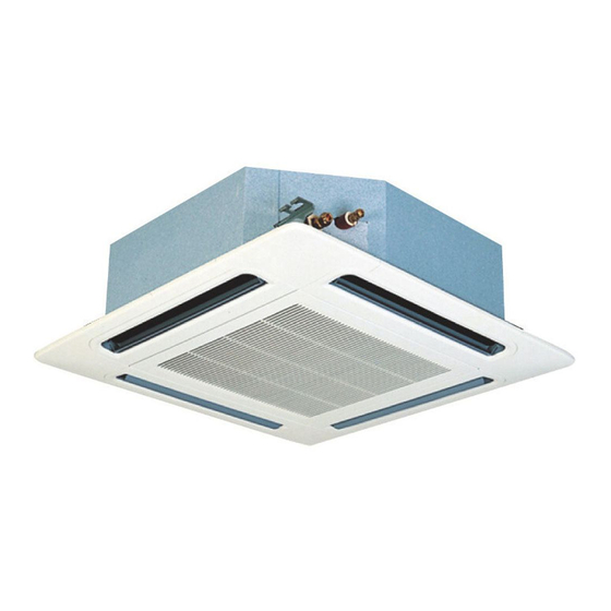
3 Piping work and refrigerant charge 3.5 Refrigerant and drain hose installation 3.5.1 RCI - 4-way cassette (1.0-6.0)FSN2E ¿ Gas refrigerant pipe installation The correct position for the gas refrigerant pipe connection is shown below. The pipe connection must be accessible from all directions (above, left or right). -
Page 102: Rcim-4-Way Cassette (Compact) (1.0-2.0)Fsn2
3 Piping work and refrigerant charge Secure the pipe with the clamp and adhesive supplied. 4% (1/25) - 1% (1/100) The drain hose must have a gradient of 4% (1/25) to 1% (1/100). Clamp (accessory) Clamp (accessory) Do not use adhesive Drainage pipe connection PVC pipe Ø... - Page 103 3 Piping work and refrigerant charge ¿ Drain pipe installation Drain pipe connection The correct position for the drain hose connection is shown below. Prepare a polyvinyl chloride (PVC) pipe with an outer diameter of 32 mm. Secure the pipe with the clamp and adhesive supplied. The drain hose must have a gradient of 1% (1/100) to 4% (1/25).
-
Page 104: Rcd - 2-Way Cassette (1.0-5.0)Fsn2
3 Piping work and refrigerant charge 3.5.3 RCD - 2-way cassette (1.0-5.0)FSN2 ¿ Gas refrigerant pipe installation The correct position for the gas refrigerant pipe connection is shown below. The pipe connection must be accessible from all directions (above, left or right). Models (1) Gas pipe mm (inches) (2) Liquid pipe mm (inches) -
Page 105: Rpc - Ceiling Type (2.0-6.0)Fsn2E
3 Piping work and refrigerant charge Then insulate the drain hose appropriately. 3.5.4 RPC - Ceiling type (2.0-6.0)FSN2E ¿ Gas refrigerant pipe installation The correct position for the gas refrigerant pipe connection is Gas pipe Gas pipe Liquid pipe Liquid pipe shown below. - Page 106 3 Piping work and refrigerant charge Unit Rear side Open Press Air inlet grille Remove the die-cut panel from the required part of the unit to install the gas refrigerant pipes. Liquid pipe Top. Gas pipe Open the die-cut panel SMGB0063 rev.
- Page 107 3 Piping work and refrigerant charge Rear. Install the pipes through it and seal them using the insulation supplied, as indicated below. Sealing plate Top. M4 screws Rear. Refrigerant pipe Sealing plate Seal with insulation Section A - B M4 screw Sealing plate Refrigerant piping Sealing plate...
- Page 108 3 Piping work and refrigerant charge Connection on the right-hand side Insert the drain hose in the clamp “A”. Push the drain hose towards the boss until it reaches the end of the pan. Tighten the screw on the wire clamp to secure the pipe around the drain connection without causing water leaks. Insulate the drain hose around the wire clamp to avoid condensation.
- Page 109 3 Piping work and refrigerant charge Place the insulating material around the drain connection. Sealing material Drain hose connection The correct position for the drain hose connection is shown below. Insulating material: Drain pipe (field-supplied) Prepare a polyvinyl chloride (PVC) pipe with an outer diameter of 26 mm.
-
Page 110: Rpi - Ducted Indoor Unit (0.8-1.5)Fsn2E
3 Piping work and refrigerant charge 3.5.5 RPI - Ducted indoor unit (0.8-1.5)FSN2E ¿ Gas refrigerant pipe installation The correct position for the gas refrigerant pipe connection is shown below. Models Gas pipe mm (inches) Liquid pipe mm (inches) Ø12.7 (1/2) Ø6.35 (1/4) N O T E When installing the pipes, leave enough space for maintenance work in the electrical box of the unit. - Page 111 3 Piping work and refrigerant charge Dimensions of the flare nuts for flared connections Nominal diameter Measurement B mm inches Ø6.35 Ø9.53 Ø12.70 Ø15.88 ¿ Drain pipe installation The correct position for the drain hose connection is shown below. Prepare a polyvinyl chloride (PVC) pipe with an outer diameter of 32 mm.
-
Page 112: Rpi - Ducted Indoor Unit (2.0-10.0)Fsn2E
3 Piping work and refrigerant charge 3.5.6 RPI - Ducted indoor unit (2.0-10.0)FSN2E ¿ Gas refrigerant pipe installation The correct position for the gas refrigerant pipe connection is shown below. RPI-(2.0-6.0) RPI-(8.0/10.0) Gas pipe Liquid pipe Drain hose Electrical box Models Gas pipe mm (inches) Liquid pipe mm (inches) - Page 113 3 Piping work and refrigerant charge Dimensions of the flare nuts for flared connections Nominal diameter Measurement B mm inches Ø6.35 Ø9.53 Ø12.70 Ø15.88 Drain piping RPI - 2 . 0~6 .0 ¿ Drain pipe installation The correct position for the drain hose connection is shown below. Drain piping RPI - 8 .
-
Page 114: Rpim - Ducted Indoor Unit (0.8-1.5)Fsn2E(-Du)
3 Piping work and refrigerant charge Then insulate the drain hose appropriately (only for RPI-(2.0– Insulating material (field-supplied) 6.0)FSN2E). 4% (1/25) - 1% (1/100) Insulating material: (factory-supplied) PVC pipe Clamp (field-supplied) (factory-supplied) Indoor unit N O T E If the relative humidity of the inlet air or the ambient air exceeds 80% in the place where the unit is installed, fit an auxiliary drain pan (field-supplied) below the indoor unit, as indicated in the figure. - Page 115 3 Piping work and refrigerant charge Models Gas pipe mm (inches) Liquid pipe mm (inches) RPIM(0.8–1.5)FSN2E Ø12.70 (1/2) Ø6.35 (1/4) N O T E When installing the pipes, leave enough space for maintenance work in the electrical box of the unit. Dimensions of the flare and thickness of the copper pipe Nominal diameter Thickness...
-
Page 116: Rpk - Wall Type (1.0-4.0)Fsn(H)2M
3 Piping work and refrigerant charge Prepare a polyvinyl chloride (PVC) pipe with an outer diameter of 25 mm. Secure the pipe with the clamp and adhesive supplied (for RPI 8/10 only). The drain hose must have a gradient of 1% (1/100) to 4% (1/25). The drain hose cannot be installed on an upwards line, not even on one section of the installation. - Page 117 3 Piping work and refrigerant charge Connection of pipes on left side Unit contour Measurements (mm) Model Insulation Pipes on right side Gas pipe RPK-(1.0/1.5)FSN(H)2M RPK–2.0FSN(H)2M Pipes for rear section RPK-(2.5-4.0)FSN(H)2M For RPK-2.0 only: if the gas pipe diameter is 12.7 mm, remove the gasket fitted at the connection.
- Page 118 3 Piping work and refrigerant charge Rear side Where the pipes are located on the left, the drain hose must also Stops be located on the left. Pipe plate Models Gas pipe mm (inches) Liquid pipe mm (inches) RPK-(1.0/1.5)FSN(H)2M Ø12.70 (1/2) Ø6.35 (1/4) RPK–2.0FSN(H)2M Ø15.88 (5/8)
-
Page 119: Rpf(I)-Floor Type (1.0-2.5)Fsn2E
3 Piping work and refrigerant charge If the drain hose connection side is to be changed: remove the drain Changing the drain pipe connection hose plug and fit it in the pipe on the opposite side. Prepare a polyvinyl chloride (PVC) pipe with an outer diameter of 26 mm. - Page 120 3 Piping work and refrigerant charge Models Gas pipe mm (inches) Liquid pipe mm (inches) Drain hose mm RPF(I)-1.5FSN2E Ø12.70 (1/2) Ø6.35 (1/4) RPF(I)-2.0FSN2E Ø18.5 Ø15.88 (5/8) RPF(I)-2.5FSN2E Ø9.53 (3/8) Dimensions of the flare and thickness of the copper pipe Nominal diameter Thickness Measurement A...
-
Page 121: Refrigerant Gas Charge
3 Piping work and refrigerant charge 3.6 Refrigerant gas charge N O T E For matters relating to the gas refrigerant charge in the installation, consult the Technical Catalogue and Service Manual corresponding to the outdoor units of the UTOPIA or SET FREE systems. SMGB0063 rev. -
Page 122: Precautions In The Event Of Refrigerant Gas Leaks
3 Piping work and refrigerant charge 3.7 Precautions in the event of refrigerant gas leaks D A N G E R Fitters and the designers of the installations must strictly observe local and national legislation, and local codes regarding safety requirements in the event of refrigerant gas leaks. 3.7.1 Maximum permissible concentration of hydrofluorocarbon (HFC) The R410A refrigerant gas, used in the equipment, is non-flammable and non-toxic. -
Page 123: Electrical Wiring
. E l e c t r i c a l w i r i n g Index Unit electrical wiring and connection..................4.1.1 Wiring and main switch selection....................112 4.1.2 Electrical connection of RCI units....................113 4.1.3 Electrical connection of RCIM units....................116 4.1.4 Electrical connection of RCD units....................118 4.1.5 Electrical connection of RPC units.................... -
Page 124: Unit Electrical Wiring And Connection
4 Electrical wiring 4.1 Unit electrical wiring and connection 4.1.1 Wiring and main switch selection Minimum size of the power supply cable wires N O T E • Follow local code and regulations to select the installation cables. • The maximum current value is used to calculate the size of the cables in line with European Standard EN60 335-1. -
Page 125: Electrical Connection Of Rci Units
Check that the cables are firmly secured to the connection terminals. Electrical connection Check that the power supply for the RCI indoor unit is 230 V. If not, replace the CN connectors on the TF transformers in the electrical box. - Page 126 4 Electrical wiring Follow the steps below to connect the remote control cable or the optional extension wire: Pass the cable through the knockout hole in the cabinet. Connect the cable to terminals A and B of the terminal strip (TB1).
- Page 127 4 Electrical wiring Part Electrical box Stop (metal) Power supply, signal and remote control wiring Screw Printed circuit board (PCB) Terminal strip (TB2) Earthing screw Terminal strip (TB1) Printed circuit board (PCB) Power supply wiring and signal wiring between the outdoor and indoor unit Remote control wiring Communication wiring between the indoor and outdoor unit...
-
Page 128: Electrical Connection Of Rcim Units
4 Electrical wiring 4.1.3 Electrical connection of RCIM units Work prior to the electrical connection Turn off the power supply switches before starting work and fit the appropriate locks and safety warnings. Wait 5 minutes after turning off the power supply switches. Check that the fans on the indoor and outdoor units are at a standstill before starting work. - Page 129 4 Electrical wiring Follow the steps below to connect the power cables to the terminal strip (TB1): C A U T I O N • To connect a power supply with neutral, connect the cables to terminals L1 and N on the terminal strip (TB1). •...
-
Page 130: Electrical Connection Of Rcd Units
4 Electrical wiring Nº Part Communication wiring between the indoor and outdoor units and between indoor units Operating control wiring. In the case of group operations using a remote control Remote control wiring Test runs C A U T I O N •... - Page 131 4 Electrical wiring Electrical connection Check that the power supply for the RCD indoor unit is 240 V. If not, replace connectors CN27 and CN28 on the TF transformers in the electrical box. Follow the steps below to connect the remote control cable or the optional extension wire: Pass the cable through the knockout hole in the cabinet.
-
Page 132: Electrical Connection Of Rpc Units
4 Electrical wiring Test runs C A U T I O N • Be careful during the test runs, as some of the safety functions remain disabled: the units operate for two hours without switching off via the thermostat. The three-minute compressor protection is not enabled during the test. - Page 133 4 Electrical wiring Follow the steps below to connect the communication cables between the outdoor and indoor unit to the terminal strip (TB): Where necessary, loosen the screws on terminals 1 and 2 on the terminal strip (TB). Connect the communication cables to terminals 1 and 2. Tighten the screw on terminals 1 and 2.
-
Page 134: Electrical Connection Of Rpi Units
4 Electrical wiring 4.1.6 Electrical connection of RPI units Work prior to the electrical connection Turn off the power supply switches before starting work and fit the appropriate locks and safety warnings. Wait 5 minutes after turning off the power supply switches. Check that the fans on the indoor and outdoor units are at a standstill before starting work. - Page 135 4 Electrical wiring Follow the steps below to connect the remote control cable or the optional extension wire: Pass the cable through the knockout hole in the cabinet. Connect the cable to terminals A and B of the terminal strip (TB).
- Page 136 4 Electrical wiring RPI-(2.0-6.0)FSN2E. Terminal board connections Nº Part PCB1 Printed circuit board. Transformer. Terminal strip. RPI-(8.0/10.0)FSN2E Terminal board connections SMGB0063 rev. 1 - 10/2010...
-
Page 137: Electrical Connection Of Rpim Units
4 Electrical wiring Nº Part PCB1 Printed circuit board. PCB2 Printed circuit board. Transformer. Terminal strip. FUSE Fuse Test runs C A U T I O N • Be careful during the test runs, as some of the safety functions remain disabled: the units operate for two hours without switching off via the thermostat. - Page 138 4 Electrical wiring Electrical connection Check that the power supply for the RPI indoor unit is 230 V. If not, replace connectors CN on the TF transformers in the electrical box. N O T E The service access panel for the indoor unit fan motor is at the bottom of the unit. Remove the service access panel.
- Page 139 4 Electrical wiring Cover the cables and the hole using a sealant to protect them from condensation and insects. Nº Part Printed circuit board. Transformer. Terminal strip. Test runs C A U T I O N • Be careful during the test runs, as some of the safety functions remain disabled: the units operate for two hours without switching off via the thermostat.
-
Page 140: Electrical Connection Of Rpk Units
4 Electrical wiring 4.1.8 Electrical connection of RPK units Work prior to the electrical connection Turn off the power supply switches before starting work and fit the appropriate locks and safety warnings. Wait 5 minutes after turning off the power supply switches. Check that the fans on the indoor and outdoor units are at a standstill before starting work. - Page 141 4 Electrical wiring Tighten the screws on terminals L1 and N. Check that the cables are correctly secured. Follow the steps below to connect the communication cables between the outdoor and indoor unit to the terminal strip (TB2): Where necessary, loosen the screws on terminals 1 and 2 on the terminal strip (TB2). Connect the communication cables to terminals 1 and 2.
- Page 142 4 Electrical wiring RPK-2.0FSN2M terminal board connections Nº Part Electrical box Connector (CN13) Remote control wiring Terminal strip (TB2) Cable secured with the tie Hole for the electrical box Operating line Hole for gas pipe and wiring installation Electricity supply line Terminal strip (TB1) RPK-(2.5-4.0)FSN2M terminal board connections Nº...
-
Page 143: Electrical Connection Of Rpf(I) Units
4 Electrical wiring 4.1.9 Electrical connection of RPF(I) units Work prior to the electrical connection Turn off the power supply switches before starting work and fit the appropriate locks and safety warnings. Wait 5 minutes after turning off the power supply switches. Check that the fans on the indoor and outdoor units are at a standstill before starting work. - Page 144 4 Electrical wiring Nº Part Printed circuit board. Transformer. Terminal box. Capacitor. Follow the steps below to connect the cable of the remote control (PC-ART/PC-P2HTE) or the optional extension wire: Pass the cable through the knockout hole in the cabinet. Connect the cable to terminals A and B in the electrical box.
-
Page 145: Electrical Connection Of Kpi Units
4 Electrical wiring 4.1.10 Electrical connection of KPI units Work prior to the electrical connection Turn off the power supply switches before starting work and fit the appropriate locks and safety warnings. Wait 5 minutes after turning off the power supply switches. Check that the fans on the indoor and outdoor units are at a standstill before starting work. -
Page 146: Network System Connection (Cs-Net Web)
4 Electrical wiring Test runs C A U T I O N • Be careful during the test runs, as some of the safety functions remain disabled: the units operate for two hours without switching off via the thermostat. The three-minute compressor protection is not enabled during the test. -
Page 147: Connection Between Units H-Link And H-Link Ii
4 Electrical wiring 4.1.12 Connection between units H-LINK and H-LINK II For mixed H-LINK and H-LINK II systems, set the H-LINK units in the first 16 positions of the system, as shown in the following figure. There are 26 systems with FSN2E indoor units. N O T E •... -
Page 148: Setting Of Dip Switches And Rsw Switches
4 Electrical wiring 4.2 Setting of DIP switches and RSW switches Turn off the power supply before setting the DIP switches. Otherwise, the switch settings are invalid. To set the position of the RSW rotary switches, insert a screwdriver into the groove of the RSW. N O T E The DIP and RSW switches of each indoor and outdoor unit must be set, although they do not all have to be set. -
Page 149: Location Of Dip Switches And Rsw Switches
4 Electrical wiring 4.2.1 Location of DIP switches and RSW switches Location of DIP switches and RSW rotary switches • RCI(M)-(1.0-6.0)FSN2(E) units • RCD-(1.0-3.0)FSN2 units • RPC-(2.0-6.0)FSN2E units • RPF(I)-(1.0-2.5)FSN2E units • RPI(M)-(0.8-6.0)FSN2E (-DU) units • RPI-(8.0/10.0)FSN2E units • RPK-(1.0/1.5)FSN(H)2M units... -
Page 150: Functions Of The Dip Switches And Rsw Switches
4 Electrical wiring • RPK-(2.0–4.0)FSN2M units PCB2 PCB1 • KPI-(252–2002)(E/H)2E units • KPI-3002H2E units 4.2.2 Functions of the DIP switches and RSW switches DSW2 switch: optional functions setting (only for RPK - FSN(H)2M) C A U T I O N Do not set the DSW2 switch, as it is factory-set prior to delivery. - Page 151 4 Electrical wiring DSW3 switch: capacity code setting This is used to set the capacity code corresponding to the power of the indoor unit. C A U T I O N Do not set the DSW3 switch, as it is factory-set prior to delivery.
- Page 152 If a high voltage is applied to TB1 terminals 1 and 2, the fuse on PCB1(M) is deactivated. Should this occur, correct the TB1 wiring and activate contact 1. Except RPK(1.0-4.0)FSN(H)2M units RPK-1.5FSN(H)2M units only DSW8 switch: not used (RCI(M) units only) Factory setting Factory setting KPI fan units with energy recovery N O T E DSW2, DSW4 and DSW6 switches have no function.
- Page 153 4 Electrical wiring DSW6 RPI-5.0FSN(1)E Factory setting RPI-5HP + Econofresh kit DSW4 RPI-5.0FSN2E Factory setting RPI-5HP + Econofresh kit SMGB0063 rev. 1 - 10/2010...
-
Page 154: Wiring Diagrams For The Kpi Indoor Units And Complementary Systems
4 Electrical wiring 4.3 Wiring diagrams for the KPI indoor units and complementary systems 4.3.1 Wiring diagrams for indoor units ¿ Wiring diagrams for the RCI-(1.0-6.0)FSN2E indoor units SMGB0063 rev. 1 - 10/2010... - Page 155 4 Electrical wiring ¿ Wiring diagrams for the RCIM-(1.0-2.0)FSN2 indoor units SMGB0063 rev. 1 - 10/2010...
- Page 156 4 Electrical wiring ¿ Wiring diagrams for the RCD-(1.0-5.0)FSN2 indoor units SMGB0063 rev. 1 - 10/2010...
- Page 157 4 Electrical wiring ¿ Wiring diagrams for the RPC-(2.0-6.0)FSN2E indoor units SMGB0063 rev. 1 - 10/2010...
- Page 158 4 Electrical wiring ¿ Wiring diagrams for the RPI-(0.8-1.5)FSN2E indoor units SMGB0063 rev. 1 - 10/2010...
- Page 159 4 Electrical wiring ¿ Wiring diagrams for the RPI-(2.0-6.0)FSN2E indoor units SMGB0063 rev. 1 - 10/2010...
- Page 160 4 Electrical wiring ¿ Wiring diagrams for the RPI-(8.0/10.0)FSN2E indoor units SMGB0063 rev. 1 - 10/2010...
- Page 161 4 Electrical wiring ¿ Wiring diagrams for the RPIM-(0.8-1.5)FSN2E (-DU) indoor units SMGB0063 rev. 1 - 10/2010...
- Page 162 4 Electrical wiring ¿ Wiring diagrams for the RPK-(1.0/1.5)FSN2M indoor units SMGB0063 rev. 1 - 10/2010...
- Page 163 4 Electrical wiring ¿ Wiring diagrams for the RPK-(1.0/1.5)FSNH2M indoor units SMGB0063 rev. 1 - 10/2010...
- Page 164 4 Electrical wiring ¿ Wiring diagram for the RPK-2.0FSN2M indoor unit SMGB0063 rev. 1 - 10/2010...
- Page 165 4 Electrical wiring ¿ Wiring diagrams for the RPK-(2.5-4.0)FSN2M indoor units SMGB0063 rev. 1 - 10/2010...
- Page 166 4 Electrical wiring ¿ Wiring diagrams for the RPF(I)-(1.0-2.5)FSN2E indoor units SMGB0063 rev. 1 - 10/2010...
-
Page 167: Wiring Diagrams For Complementary Systems
4 Electrical wiring 4.3.2 Wiring diagrams for complementary systems ¿ KPI-(252-802)(E/H)2E energy / heat recovery unit SMGB0063 rev. 1 - 10/2010... - Page 168 4 Electrical wiring ¿ KPI-(1002-2002)(E/H)2E energy / heat recovery unit SMGB0063 rev. 1 - 10/2010...
- Page 169 4 Electrical wiring ¿ KPI-3002H2E heat recovery unit SMGB0063 rev. 1 - 10/2010...
- Page 170 4 Electrical wiring SMGB0063 rev. 1 - 10/2010...
-
Page 171: Control System
. C o n t r o l s y s t e m Index Device control system........................ 5.1.1 Printed circuit boards for RCI(M) indoor units................161 5.1.2 Printed circuit boards for RCD indoor units................... 163 5.1.3 Printed circuit board for RPC, RPF(I), RPI(M) units..............166 5.1.4... -
Page 172: Device Control System
5 Control system 5.1 Device control system Purpose of control Cooling operation Heating operation Defrost mode Frequency control is determined with Frequency control is determined with the following parameters: the following parameters: • Difference between the air inlet • Difference between the air inlet temperature and the set air Compressor control frequency Fixed frequency (stop the compressor... -
Page 173: Printed Circuit Boards For Rci(M) Indoor Units
Control pressure switch Electric heater Microcomputer 5.1.1 Printed circuit boards for RCI(M) indoor units C A U T I O N Turn off the power supply before setting the DIP switches. If not, the settings will not be valid. SMGB0063 rev. 1 - 10/2010... - Page 174 5 Control system N O T E • The symbol “■” indicates the position of the DIP switches. The figures show the setting before transmission or after selection. • If the “■” mark is not displayed, this indicates that the position of the pin is not affected. The indoor unit PCB operates with five types of DIP switches and two rotary switches.
-
Page 175: Printed Circuit Boards For Rcd Indoor Units
5 Control system Connector indication PCN1 220 V transformer PCN5 Electric heater for dew protection PCN6 Drain pump motor PCN7 Power supply (1-R, 3-S) PCN201 Power supply (1-R, 3-S) PCN202 Power supply (1-R, 3-S) PCN203 DC motor control PCN301 Terminal board connections PCN302 PCB2 connection THM1... - Page 176 5 Control system N O T E • The symbol “■” indicates the position of the DIP switches. The figures show the setting before transmission or after selection. • If the ■ mark is not displayed, this indicates that the position of the pin is not affected. The indoor unit PCB operates with five types of DIP switches and two rotary switches.
- Page 177 5 Control system Connector indication PCN1 220 V transformer PCN5 Electric heater for dew protection PCN6 Drain pump motor PCN7 Power supply (1-R, 3-S) PCN201 Power supply (1-R, 3-S) PCN202 Power supply (1-R, 3-S) PCN203 DC motor control THM1 Air inlet THM2 Air outlet THM3...
-
Page 178: Printed Circuit Board For Rpc, Rpf(I), Rpi(M) Units
5 Control system 5.1.3 Printed circuit board for RPC, RPF(I), RPI(M) units C A U T I O N Turn off the power supply before setting the DIP switches. If not, the settings will not be valid. N O T E •... -
Page 179: Printed Circuit Board For Rpi-(8.0/10.0) Fsn2E Units
5 Control system Connector indication PCN1 220 V transformer PCN2 Indoor fan motor internal thermostat PCN3 Not used PCN5 Not used PCN6 Drain pump motor (RPI) PCN7 Power supply (1-R, 2-S, 3-N, 4-E) PCN8 Capacitor PCN10 Fan motor power supply PCN11 Fan motor speed control PCN301... - Page 180 5 Control system N O T E • The symbol “■” indicates the position of the DIP switches. The figures show the setting before transmission or after selection. • If the “■” mark is not displayed, this indicates that the position of the pin is not affected. The indoor unit PCB operates with four types of DIP switches, a slide switch and a rotary switch.
-
Page 181: Printed Circuit Board For Rpk-Fsn(H)2M Units
5 Control system Connector indication PCN1 220 V transformer PCN2 Indoor fan motor internal thermostat PCN3 Fan stoppage alarm signal PCN6 Drain pump motor (RPI) PCN7 Power supply (1-R, 2-S, 3-N, 4-E) THM1 Air inlet THM2 Air outlet THM3 Liquid pipe THM4 Remote thermistor (THM-R2 AE) THM5... - Page 182 5 Control system RPK-(1.0/1.5)FSN(H)2M The indoor unit PCB operates with four types of DIP switches, a slide switch, a rotary switch and a button switch. The position is as follows: LED indicator This LED indicates the transmission status between the indoor unit and the LED1 remote control.
- Page 183 5 Control system Switch indication PSW301 Changeover switch for emergency operation DSW6, RSW1 Indoor unit setting DSW5, RSW2 Refrigerant cycle number DSW2 Optional functions DSW3 Capacity code DSW7 Fuse re-establishing SMGB0063 rev. 1 - 10/2010...
-
Page 184: Printed Circuit Board For Kpi Complementary Systems
5 Control system RPK-(2.0/4.0)FSN(H)2M The indoor unit PCB operates with four types of DIP switches, a slide switch, a rotary switch and a button switch. The position is as follows: LED indicator This LED indicates the transmission status between the indoor unit and the LED1 remote control. - Page 185 5 Control system N O T E • The symbol “■” indicates the position of the DIP switches. The figures show the setting before transmission or after selection. • If the “■” mark is not displayed, this indicates that the position of the pin is not affected. LED indicator LED1 Green...
- Page 186 5 Control system Switch indication DSW3 Capacity code DSW5 Refrigerant cycle number DSW6 Unit model code DSW7 Fuse recovery and remote control selector Indoor unit number settings Switch (PC-ART or PC-P2HTE) SMGB0063 rev. 1 - 10/2010...
-
Page 187: Safety Protection And Control
• Fan motor protection: internal thermostat located in the fan motor winding. This stops the fan motor when the winding temperature exceeds the set value. Setting control and safety devices for indoor units Model RCI(M) RPIM RPF(I) Remarks Switch °C 145±5... -
Page 188: Standard Control Functions
5 Control system 5.3 Standard control functions 5.3.1 Freeze protection during the cooling or dehumidification process SMGB0063 rev. 1 - 10/2010... -
Page 189: Indoor Electronic Expansion Valve Control
5 Control system 5.3.2 Indoor electronic expansion valve control After supplying power, the electronic expansion valve closes fully before starting to open. When the compressor stops, the electronic expansion valve closes fully to set its opening. When it starts (the compressor is activated), the electronic expansion valve opens to a specific degree during cooling operation, 1 minute. -
Page 190: Activation Of The Control With Protection Device
5 Control system 5.3.3 Activation of the control with protection device SMGB0063 rev. 1 - 10/2010... -
Page 191: Automatic Cooling/Heating Operation Control
5 Control system 5.3.4 Automatic cooling/heating operation control 5.3.5 Preventive high-pressure increase control This function is used to avoid an abnormal condition (alarm: 02) when the outdoor air flow drops due to seasonal winds blowing against the air outlet. When CMC is enabled in cooling operation, PSC is enabled and Tc is greater than Tc1+4 °C, operations with forced thermostat disabling are started. - Page 192 5 Control system SMGB0063 rev. 1 - 10/2010...
-
Page 193: Optional Functions
6 Optional functions . O p t i o n a l f u n c t i o n s Index Indoor units..........................6.1.1 Available ports..........................182 6.1.2 Optional signal configuration......................183 6.1.3 Programming with PC-ART......................188 6.1.4 Description of optional input signals....................189 6.1.5 Description of optional output signals................... -
Page 194: Indoor Units
6 Optional functions 6.1 Indoor units 6.1.1 Available ports The system has eight optional input signals and six output signals. Both types of signal are programmed into the indoor unit PCB: connector CN3 for input signals and connectors CN7 and CN8 for output signals. Output connector CN7 has two ports and output connector CN8 has one port, which are used to configure three output options of the eight available in the system. -
Page 195: Optional Signal Configuration
6 Optional functions Indication Connections Manufacturer or Component Remarks specifications Reduced power relay model Voltage between the relay Auxiliary relay (X2) OMRON: MY1F or terminals 12 Vdc, 75 mA equivalent Voltage between the Contact (SS1) (x1) (example) Manual type contactor terminals 230 V, 5 mA Optional part PCC-1A Five cables with connectors... - Page 196 6 Optional functions Optional input signals N O T E If an input signal is set, the on-screen display on the remote control automatically changes to the following. SMGB0063 rev. 1 - 10/2010...
- Page 197 6 Optional functions Remote control screen (input Indication Input signal Application Port signal) Not set Not set This signal controls the unit through an external thermostat. Control by field-supplied room thermostat N O T E (cooling) It can reduce summer cooling problems in certain applications This signal controls the...
- Page 198 6 Optional functions Remote control screen (input Indication Input signal Application Port signal) This signal controls the stoppage of the system from a remote location. N O T E Function unit It is extremely practical stoppage (by pulse) in hotels and offices to control indoor units from the building...
- Page 199 6 Optional functions Remote control screen (input Indication Input signal Application Port signal) • Not set Not set • CN7 for RPK units This signal permanently controls the status of the unit. • Operation signal • CN7 for N O T E RPK units It is extremely useful centralised...
-
Page 200: Programming With Pc-Art
6 Optional functions Remote control screen (input Indication Input signal Application Port signal) This signal controls the status • compressor. Function 2: unit stoppage extremely useful • (by pulse) controlling RPK units thermostat switched off on indoor units. Cancellation It is extremely useful for •... -
Page 201: Description Of Optional Input Signals
6 Optional functions Changing the optional signals and setting conditions In optional setting mode, the remote control indication changes as shown below: The assigned port for the input signal and the output signal are displayed in the time indication segments for the timer setting. See the following table for the indicated port and the PCB connector of the indoor unit. - Page 202 6 Optional functions • Difference of over 1.5 degrees. • Do not use a mercury thermostat. • The remote control must remain connected to the unit. When the power supply is reconnected, start the unit by pressing the on button. The compressor will then run under the control of the field-supplied thermostat. All other functions are controlled in the normal manner via the remote control.
- Page 203 6 Optional functions A time chart with the uses of the function is shown below. N O T E The collection of signals during the first 10 seconds after connecting the power supply is not available due to component initialisation. With this optional function, contact B can be used through the optional setting of the remote control.
-
Page 204: Description Of Optional Output Signals
6 Optional functions N O T E • The remote control thermistor cannot be used if a remote temperature sensor is used. • The heating temperature calibration function is automatically cancelled in heating operation. • If a remote temperature sensor is used, it must be positioned according to the following requirements: –... - Page 205 6 Optional functions This optional signal is used to pick up the heating operation signal. The X2 auxiliary relay contact closes when the heating operation signal is enabled, regardless of whether the thermostat signal is enabled or disabled. Connect the wiring and use the materials as indicated in Available ports, see on page 194.
-
Page 206: Complementary Systems
6 Optional functions 6.2 Complementary systems 6.2.1 Econofresh Kit ¿ Available ports The system has three optional input signals programmed into the PCB using connector CN3 on the RPI unit and using the remote control. Connector CN3 has two ports for configuring the optional input signals of the Econofresh kit. The outdoor cooling function E1 requires no CN3 connector setting. - Page 207 6 Optional functions ¿ Compatibilities between optional signals The following table shows the compatibility between the different optional signals: PC-ART Remote Wireless Outdoor Room Remote Enthalpy optional control remote cooling sensor thermostat thermistor sensor functions thermistor control mode Room – –...
-
Page 208: Remote Controls
6 Optional functions 6.3 Remote controls 6.3.1 Optional remote control functions Programming and setting mode Check that the unit is stopped, if not switch it off. Press the OK and RESET buttons on the remote control at the same time for more than 3 seconds. - Page 209 6 Optional functions Returning to normal mode from optional function setting mode Press RESET to store the optional function settings and return to normal mode. Selection of another indoor unit In optional function setting mode, press TEMP ▲ or TEMP ▼ on the remote control to select the indoor unit on which the optional function is to be set.
-
Page 210: List Of Optional Remote Control Functions
6 Optional functions 6.3.2 List of optional remote control functions Indivi dual Condition Part Optional function Settings Description settin setting Standard setting. Selected temperature This function is used when the +4 °C increase temperature setting displayed on the Elimination of the heating remote control and the inlet air temperature offset Offset... - Page 211 6 Optional functions Indivi dual Condition Part Optional function Settings Description settin setting Standard setting. No offset Selected This function is used to obtain longer Cooling temperature offset temperature cooling periods. -1 °C Selected temperature -2 °C Not used – Used as setting Not used –...
- Page 212 6 Optional functions Indivi dual Condition Part Optional function Settings Description settin setting Air temperature control using the unit air inlet thermistor Air temperature control using the remote control This function determines the thermistor to Remote control thermistor thermistor control the air temperature. Air temperature control using the average...
- Page 213 6 Optional functions Indivi dual Condition Part Optional function Settings Description settin setting Not available This function stores the settings of the unit in the event of a cut in the electric power Power on/off 1 supply. The unit is restarted when the Available power is re-established.
- Page 214 6 Optional functions Indivi dual Condition Part Optional function Settings Description settin setting KPI: Standard 30 minutes Pre-cooling / pre-heating This function delays start-up of the 60 minutes period ventilation unit with energy / heat recovery Econofresh kit Standard sensor Not used Used as setting Not used...
- Page 215 6 Optional functions Indivi dual Condition Part Optional function Settings Description settin setting Function not valid This function is used to switch off the timer Automatic timer off setting automatically when the unit has been started by remote control. 04-24 (04-24) h 0.5 h 1.5 h...
- Page 216 6 Optional functions Indivi dual Condition Part Optional function Settings Description settin setting Not available Temperature setting This function is used to prevent changes to Available interlock the temperature setting. (factory setting) Not available Fan speed selection This function is used to prevent changes to Available interlock the fan speed.
-
Page 217: Description Of The Optional Remote Control Functions
6 Optional functions Indivi dual Condition Part Optional function Settings Description settin setting Operating mode change disabled (factory setting) This function is used to configure restrictions to the operating mode. Operating mode change Operating restriction mode set by the central control + FAN mode Unlimited operating mode... - Page 218 6 Optional functions Everyone has a different perception of coolness, heat and air flow and, therefore, this issue should be discussed with the client and the unit set according to the results of the conversation. Settings Condition setting Not available Available b3 –...
- Page 219 6 Optional functions b6 – Temperature setting lock This function is used when the temperature setting does not have to be changed. Once the temperature on the unit has been selected, this function prevents it from being modified from the remote control. Settings Condition setting Not available...
- Page 220 C4 – Not used C5 – Static pressure selection The fan speed increase selection function is only available for RCI and RCD units. It is used to increase the fan speed on the indoor ducted units. N O T E In the case of RPI units, this setting is used to select the static pressure.
- Page 221 6 Optional functions C8 – Remote control thermistor This function is useful when the unit is to be controlled by the thermistor included in the remote control instead of by the suction air thermistor. It determines the thermistor to control the air temperature. N O T E When the function is set to "01"...
- Page 222 6 Optional functions d1 – Power on/off 1 This function stores the settings of the unit in the event of a cut in the electric power supply. The unit is restarted when the power is re-established. C A U T I O N When this function is used without anyone controlling the unit, set the system monitoring mode to avoid risks.
- Page 223 6 Optional functions d5 – Heating air temperature drop prevention. This function prevents a drop in the air temperature by decreasing the fan speed, apart from the settings on the remote control. Settings Condition setting Not available Available Indications on the remote Actual fan speed control High...
- Page 224 6 Optional functions The following table shows the air flow rate setting using the remote control and the actual air flow rate of the total heat exchanger when this function is enabled. Settings Condition setting Not available Available Air flow rate setting with the remote control Air flow rate on the total heat exchanger Medium Medium...
- Page 225 6 Optional functions E9 – Not used Settings Condition setting Not used Used as setting for conditions 00 EA – Not used Settings Condition setting Not used Used as setting for conditions 00 Eb – Fan operating control after stoppage of the indoor unit in cooling mode This function reduces the unit fan speed to reduce the spreading of smells and humidity.
- Page 226 6 Optional functions It is not possible to cancel or change the timer off setting during automatic timer off setting. However, it can be cancelled when the unit is stopped. When the unit is restarted, the off timer setting period is established according to the optional setting.
- Page 227 6 Optional functions Example: Automatic temperature Reset for 25 °C in air conditioning: Figu Description Temperature setting changed from 25 °C to 20 °C using the remote control. The cold operation at 20°C is temporarily enabled If the operation is not defined within a specific period, the temperature configuration returns to 25 °C automatically.
- Page 228 6 Optional functions F6 – Automatic heating temperature release This function is used to set automatic temperature release for the HEAT function. Setting Condition setting 19 °C 20 °C 21-24 (21-24) °C 25 °C (factory setting) 26-28 (26-28) °C 29 °C 30 °C F7 –...
- Page 229 6 Optional functions An example is shown in the following figure: Fd – Upper heating temperature setting limit This function is used to define an upper temperature setting limit for the HEAT function. This function enables the heating range to be reduced for configuration using the remote control. The setting condition is shown below. Setting Contents Standard...
- Page 230 6 Optional functions H2 – Automatic control indication This function is used to display or hide the automatic control indication. Setting condition Contents Display Hide H3 – Operation mode change restriction This function is used to configure restrictions to the operating mode. Setting condition Contents Operating mode change disabled (factory setting)
-
Page 231: Optional Functions For Pc-Arh Remote Controls
6 Optional functions 6.3.4 Optional functions for PC-ARH remote controls Optional setting function To access the optional setting mode with the unit at a standstill, press the MODE and FAN SPEED buttons at the same time for over 3 seconds until the image displayed on the screen changes: Press TEMP▼... - Page 232 6 Optional functions Code Part Setting options 00: Normal (temperature setting +4 °C) Heating temperature setting cancellation 01: Cancelled (temperature setting) 02: Temperature setting +2 °C *(1) 00: Disabled Simultaneous cooling/ heating mode 01: Enabled 00: Disabled Increase of indoor fan 01: High 1 02: High 2 00: Disabled...
-
Page 233: Optional Functions On Wireless Remote Controls
6 Optional functions 6.3.5 Optional functions on wireless remote controls PC-RLH8/9/11 Switch off all power supplies before setting the DIP switches. DIP switch Optional function Secondary receiver Available – – – setting Indoor unit Only available for PC- – identification ALHD, 11, 13 PC-RLH8/9/11/13 Switch off all power supplies before setting the DIP switches. - Page 234 6 Optional functions SMGB0063 rev. 1 - 10/2010...
-
Page 235: Test Run
7 Test run . T e s t r u n Index Checks prior to the test run......................7.1.1 Check points..........................224 7.1.2 Check procedure........................... 224 Test procedure using the remote control..................Test procedure using the wireless remote control..............Test run check list........................SMGB0063 rev. -
Page 236: Checks Prior To The Test Run
7 Test run 7.1 Checks prior to the test run • Once installation is complete, carry out the test run in line with the procedure described below. The system can be handed over to the client once the test has been correctly completed. •... - Page 237 7 Test run 13 The operating temperature: • Cooling operation Indoor DB2 1.5 °C and higher. Indoor WB 16 °C and higher. Outdoor DB 0 °C and higher. • Heating operation Indoor DB27 °C and below. 14 Use shielded cables for the installation to avoid electrical noise. This must be less than 1000 m in length and meet with national and local regulations.
-
Page 238: Test Procedure Using The Remote Control
7 Test run 7.2 Test procedure using the remote control Switch on the power supply to the indoor and outdoor units. Select the TEST RUN mode using the remote control: press MODE and OK buttons at the same time for more than 3 seconds. If the indication TEST RUN or the counter number of the units connected to the control (e.g. - Page 239 7 Test run Check the indication on the remote control: Inspection points after Indication on the remote Unit status Fault switching off the power control supply Connection order of each terminal board. The fuse on the PCB is likely to have been disabled during a incorrect wiring.
-
Page 240: Test Procedure Using The Wireless Remote Control
7 Test run 7.3 Test procedure using the wireless remote control N O T E The test run cannot be carried out using the wireless remote control if the remote control is being used or if several units (SET-FREE, DC INVERTER and UTOPIA series) are running at the same time. In this case, carry out the test using the remote control. - Page 241 7 Test run Set the operating mode by pressing the MODE button. TEST RUN mode is operational. Start the test run using the RUN/STOP button. When the unit receives the commands, the yellow LED will light up for a moment. Check that the device has received the commands and that the selected mode is correct.
-
Page 242: Test Run Check List
7 Test run 7.4 Test run check list MODEL: SERIAL NO. COMPRESSOR MFG NO NAME AND ADDRESS OF CUSTOMER: DATE: Does the indoor unit fan turn in the correct direction? __________ Has the unit been running for at least twenty (20) minutes? __________ Check the temperature of the room: Inlet: DB/WB _____°C... -
Page 243: Troubleshooting
8 Troubleshooting . T r o u b l e s h o o t i n g Index Self-check of the indoor unit PCB (for RPK only)............... Electronic expansion valve check procedure................Procedure for checking fan motors in indoor units..............Inspection of other components.................... -
Page 244: Self-Check Of The Indoor Unit Pcb (For Rpk Only)
8 Troubleshooting 8.1 Self-check of the indoor unit PCB (for RPK only) • Self-check procedure using indoor PCB relays. – To check faults on the indoor unit PCB due to malfunctioning. – To check faults on the indoor unit PCB according to the results of the self-check using the CHECK button on the remote control and the auto-control function. -
Page 245: Electronic Expansion Valve Check Procedure
8 Troubleshooting 8.2 Electronic expansion valve check procedure Valve position Electronic expansion valve Check the temperature of the piping in the heating process. Locked fully closed Failure of the temperature to rise indicates a fault. Locked slightly open The following conditions indicate a fault: •... -
Page 246: Procedure For Checking Fan Motors In Indoor Units
Name and abbreviation of the cable colours used: Black Brown Yellow Green Blue Grey Orange White Power Indoor units Wiring diagram Cable no. Resistance (Ω) input RCI-1.0FSN2E RCI-1.5FSN2E 56 W DC motor — — RCI-2.0FSN2E RCI-3.0FSN2E RCI-4.0FSN2E RCI-5.0FSN2E 108 W DC motor — — RCI-6.0FSN2E RCIM-1.0FSN2... - Page 247 8 Troubleshooting Power Indoor units Wiring diagram Cable no. Resistance (Ω) input 32.10 BLK1-2RED RPC-4.0FSN2E 24.50 RED2-3YEL RPC-5.0FSN2E 180 W 24.50 YEL3-4GRY RPC-6.0FSN2E 44.70 RED2-6WHT to 25 23.60 BLK1-2RED 23.50 RED2-3BLU RPI-0.8FSN2E 23.40 88 W BLU3-4GRY RPI-1.0FSN2E 23.50 GRY4-5YEL 38.40 RED2-6WHT to 20 °C 23.60...
- Page 248 8 Troubleshooting Power Indoor units Wiring diagram Cable no. Resistance (Ω) input 19.60 BLK1-2RED 15.70 RED2-3BLU 16.00 RPI-3.0FSN2E 150 W BLU3-4GRY 16.00 GRY4-5YEL 45.20 RED2-6WHT to 20 °C 15.80 BLK1-2RED 4.00 RED2-3BLU RPI-4.0FSN2E 8.00 225 W BLU3-4GRY RPI-5.0FSN2E 8.00 GRY4-5YEL 24.00 RED2-6WHT to 20 °C...
- Page 249 8 Troubleshooting Power Indoor units Wiring diagram Cable no. Resistance (Ω) input 231.70 BLK1-2RED 198.70 RED2-3WHT RPF(I)-1.0FSN2E 136.20 28 W WHT3-4BLU RPF(I)-1.5FSN2E 71.20 BLU4-5ORN 202.40 ORN5-6YEL to 20 °C BLK1-2RED 97.90 RED2-3WHT 138.10 WHT3-4BLU 61.60 RPF(I)-2.0FSN2E 45 W BLU4-5ORN 35.20 RPF(I)-2.5FSN2E ORN5-6YEL 61.00...
-
Page 250: Inspection Of Other Components
8 Troubleshooting 8.4 Inspection of other components Component name Unit model Model code Resistance RCI-(1.0-6.0)FSN2E RCIM - (1.0-2.0)FSN2E ADP-1403 139.00 a 21 °C Drain motor RPI-(2.0-6.0)FSN2E RCD-(1.0-5.0)FSN2E KJV-1004 347.00 to 20 °C SMGB0063 rev. 1 - 10/2010... -
Page 251: Spare Parts
9 Spare parts . S p a r e p a r t s Index RCD-(1.0-3.0)FSN2........................RCD-(4.0-5.0)FSN2........................RPC-(4.0-6.0)FSN2E......................... RPI-(0.8-1.5)FSNE........................RPI-(8.0-10.0)FSN2E......................... RPIM-(0.8-1.5)FSNE(-DU)......................RPK-(1.0-1.5)FSN2E........................RPK-(1.0-1.5)FSN(H)2M......................RPK-(2.0)FSN2E........................9.10 RPK-(2.5-4.0)FSN2E........................9.11 RPF-(1.0-2.5)FSN2E........................9.12 RPFI-(1.0-2.5)FSN2E......................... SMGB0063 rev. 1 - 10/2010... -
Page 252: Rcd-(1.0-3.0)Fsn2
9 Spare parts 9.1 RCD-(1.0-3.0)FSN2 SMGB0063 rev. 1 - 10/2010... - Page 253 9 Spare parts Number Part name Remarks Fuse 5A for the control circuit Capacitor 4/5MF 440VAC U15A Thermistor THM1 thermistor for air inlet U15B Thermistor THM2 thermistor for air outlet U15C Thermistor THM3 thermistor, protection against liquid freezing U15D Thermistor THM5 thermistor for gas Expansion valve —...
-
Page 254: Rcd-(4.0-5.0)Fsn2
9 Spare parts 9.2 RCD-(4.0-5.0)FSN2 SMGB0063 rev. 1 - 10/2010... - Page 255 9 Spare parts Number Part name Remarks Fuse 5A for the control circuit U14A Capacitor 4MF 440VAC U14B Capacitor 5MF 440VAC U15A Thermistor THM1 thermistor for air inlet U15B Thermistor THM2 thermistor for air outlet U15C Thermistor THM3 thermistor, protection against liquid freezing U15D Thermistor THM5 thermistor for gas...
-
Page 256: Rpc-(4.0-6.0)Fsn2E
9 Spare parts 9.3 RPC-(4.0-6.0)FSN2E SMGB0063 rev. 1 - 10/2010... - Page 257 9 Spare parts Number Part name Remarks Printed circuit board terminals Electrical box Assembly of (components + harness) Capacitor 4uF/5uF U15A Thermistor THM3 thermistor for liquid piping U15B Thermistor THM5 thermistor for gas pipe U15C Thermistor THM1 thermistor for air inlet U15D Thermistor THM2 thermistor for air outlet...
-
Page 258: Rpi-(0.8-1.5)Fsne
9 Spare parts 9.4 RPI-(0.8-1.5)FSNE SMGB0063 rev. 1 - 10/2010... - Page 259 9 Spare parts Number Part name Remarks Printed circuit board terminals — Remote control PC-ART (optional) Electrical box Assembly of (components + harness) Capacitor 3.15uF/4uf U15A Thermistor For the liquid piping U15B Thermistor For the gas pipe U15C Thermistor For the air inlet U15D Thermistor For the air outlet...
-
Page 260: Rpi-(8.0-10.0)Fsn2E
9 Spare parts 9.5 RPI-(8.0-10.0)FSN2E SMGB0063 rev. 1 - 10/2010... - Page 261 9 Spare parts Number Part name Remarks Printed circuit board terminals — SW remote control PC-ART (optional) Fuse Electrical box Assembly of (components + harness) Capacitor 20uF/25uF U15A Thermistor THM3 thermistor for liquid piping U15B Thermistor THM5 thermistor for gas pipe U15C Thermistor THM1 thermistor for air inlet...
-
Page 262: Rpim-(0.8-1.5)Fsne(-Du)
9 Spare parts 9.6 RPIM-(0.8-1.5)FSNE(-DU) SMGB0063 rev. 1 - 10/2010... - Page 263 9 Spare parts Number Part name Remarks U00A Printed circuit board terminals — SW remote control PC-ART (optional) Electrical box Assembly of (components + harness) Capacitor 2.5uF U15A Thermistor THM3 thermistor for liquid piping U15B Thermistor THM5 thermistor for gas pipe U15C Thermistor THM1 thermistor for air inlet...
-
Page 264: Rpk-(1.0-1.5)Fsn2E
9 Spare parts 9.7 RPK-(1.0-1.5)FSN2E SMGB0063 rev. 1 - 10/2010... - Page 265 9 Spare parts Number Part name Remarks Remote control PC-LH3 (optional) U04A Fuse 5A (for unit control) U15A Thermistor THM1 thermistor for air inlet U15B Thermistor THM2 thermistor for air outlet U15C Thermistor THM3 thermistor for protection against liquid freezing. U15D Thermistor THM5 thermistor for gas...
-
Page 266: Rpk-(1.0-1.5)Fsn(H)2M
9 Spare parts 9.8 RPK-(1.0-1.5)FSN(H)2M U15B U71B U15C U15D U15A U71C U85A U85B U31A U85D U85C U31B EV-1.5N U21 U71A Expansion Valve Kit SMGB0063 rev. 1 - 10/2010... - Page 267 9 Spare parts Number Part name Remarks Fuse — U15A Thermistor Air inlet thermistor THM1 U15B Thermistor Air outlet thermistor THM2 U15C Thermistor Ice protection thermistor THM3 U15D Thermistor Gas thermistor THM5 Expansion valve U31A Air filter Left side U31B Air filter Right side Bearing...
-
Page 268: Rpk-(2.0)Fsn2E
9 Spare parts 9.9 RPK-(2.0)FSN2E SMGB0063 rev. 1 - 10/2010... - Page 269 9 Spare parts Number Part name Remarks SW remote control PC-LH3 (optional) U04A Fuse 5A (for unit control) U15A Thermistor THM1 thermistor for air inlet U15B Thermistor THM2 thermistor for air outlet U15C Thermistor THM3 thermistor for protection against liquid freezing. U15D Thermistor THM5 thermistor for gas.
-
Page 270: Rpk-(2.5-4.0)Fsn2E
9 Spare parts 9.10 RPK-(2.5-4.0)FSN2E SMGB0063 rev. 1 - 10/2010... - Page 271 9 Spare parts Number Part name Remarks SW remote control PC-LH3A (optional) U04A Fuse 5A (for unit control) U15A Thermistor THM1 thermistor for air inlet U15B Thermistor THM2 thermistor for air outlet U15C Thermistor THM3 thermistor for protection against liquid freezing. U15D Thermistor THM5 thermistor for gas.
-
Page 272: Rpf-(1.0-2.5)Fsn2E
9 Spare parts 9.11 RPF-(1.0-2.5)FSN2E SMGB0063 rev. 1 - 10/2010... - Page 273 9 Spare parts Number Part name Remarks SW remote control PC-LH3A (optional) U04A Fuse 5A (for unit control) U15A Thermistor THM1 thermistor for air inlet U15B Thermistor THM2 thermistor for air outlet U15C Thermistor THM3 thermistor for protection against liquid freezing. U15D Thermistor THM5 thermistor for gas...
-
Page 274: Rpfi-(1.0-2.5)Fsn2E
9 Spare parts 9.12 RPFI-(1.0-2.5)FSN2E SMGB0063 rev. 1 - 10/2010... - Page 275 9 Spare parts Number Part name Remarks Printed circuit board terminals — SW remote control PC-P2HTE/PC-ART (optional) Cord expansion valve — Cord expansion valve — Capacitor 2uF/4uF U15A Thermistor THM1 thermistor for air inlet U15B Thermistor THM5 thermistor for gas pipe U15C Thermistor THM3 thermistor for liquid piping...
- Page 276 9 Spare parts SMGB0063 rev. 1 - 10/2010...
-
Page 277: Servicing
10 Servicing . S e r v i c i n g Index 10.1 RCI - 4-way cassette (1.0-6.0)FSN2E..................10.1.1 Removal of the long-lasting air filter....................268 10.1.2 Removal of the air inlet grille......................268 10.1.3 Removal of the electrical box cover....................269 10.1.4... - Page 278 10 Servicing 10.4.4 Removal of the fan parts....................... 299 10.4.5 Removal of the drain mechanism....................300 10.4.6 Removal of the float switch......................301 10.4.7 Removal of the air filter......................... 301 10.5 RPI-(8.0-10.0)FSN2E - Ducted indoor unit................. 10.5.1 Removal of the electrical box cover....................303 10.5.2 Removal of electrical components....................
- Page 279 10 Servicing 10.9.6 Removal of the printed circuit board (PCB)................... 348 10.9.7 Removal of the thermistors from the liquid and gas piping............349 10.9.8 Removal of the fan motor......................349 10.9.9 Removal of the printed circuit board (PCB)................... 349 10.9.10 Removal of the thermistors from the liquid and gas piping............
-
Page 280: Rci - 4-Way Cassette (1.0-6.0)Fsn2E
10 Servicing 10.1 RCI - 4-way cassette (1.0-6.0)FSN2E 10.1.1 Removal of the long-lasting air filter Nº Part Button Air inlet grille The long-lasting filter is located inside the air inlet grille. Press the buttons in the direction indicated by the arrows and open the air inlet grille. -
Page 281: Removal Of The Electrical Box Cover
10 Servicing 10.1.3 Removal of the electrical box cover Nº Part Screws Electrical box cover The electrical box can be removed by opening the air inlet grille. Remove the two set screws from the electrical box cover and remove it. SMGB0063 rev. -
Page 282: Removal Of The Optional Air Panel
10 Servicing 10.1.4 Removal of the optional air panel Nº Part Main PCB Connector CN17 for the louver motor Remove the electrical box cover Removal of the electrical box cover, see on page 269 and separate connector CN17 from the louver motor in the main indoor PCB. -
Page 283: Removal Of The Fan Duct And Motor
10 Servicing 10.1.5 Removal of the fan duct and motor Nº Part Plastic clamp PCB electrical box set screws Remove the air inlet grille Removal of the air inlet grille, see on page 268. Remove the electrical box as follows: Disconnect the thermistors (THM2), the drainage motor connector (PCN6) and the float switch connector (CN14) from the PCB. -
Page 284: Removal Of The Printed Circuit Board (Pcb)
10 Servicing 10.1.7 Removal of the printed circuit board (PCB) Nº Part Power supply PCB Control PCB Remove the air inlet grille as indicated in chapter Removal of the air inlet grille, see on page 268. Remove the electrical box cover as indicated in chapter Removal of the electrical box cover, see on page 269. -
Page 285: Removal Of The Drain Pan
10 Servicing 10.1.8 Removal of the drain pan Remove the optional air panel Removal of the optional air panel, see on page 270. Remove the electrical box cover Removal of the electrical box cover, see on page 269. Separate the connectors from: The air outlet thermistor. -
Page 286: Removal Of The Float Switch
10 Servicing 10.1.10 Removal of the float switch Nº Part Securing plate screw Securing base Drain mechanism Float switch Remove the drain pan Removal of the drain pan, see on page 273. Loosen the resin nut securing the float switch and remove it. Remove the two screws securing the drain mechanism to remove the mechanism. -
Page 287: Removal Of The Electronic Expansion Valve Coil
10 Servicing 10.1.12 Removal of the electronic expansion valve coil Nº Part Expansion valve Remove the optional air panel in line with the instructions given in chapter Removal of the optional air panel, see on page 270. Remove the fan duct in line with the instructions given in chapter Bellmouth removal, see on page 271. -
Page 288: Removal Of The Automatic Louver Motor
10 Servicing Tighten the nut by hand and apply the torque value: 12 Nm - 15 Nm. N O T E • Do not apply significant force to the motor, such as rotational torque or bending load, while holding it with your hand and tightening the nut. -
Page 289: Rcim - 4-Way Cassette (1.0-2.0)Fsn2 (Compact)
10 Servicing 10.2 RCIM - 4-way cassette (1.0-2.0)FSN2 (compact) 10.2.1 Removal of the air filter The long-lasting filter is located inside the air inlet grille. Press the buttons in the direction indicated by the arrows and open the air inlet grille. Remove the filter from the grille by holding onto the lower part of the grille and the filter and detaching the blocked part. -
Page 290: Removal Of The Optional Air Panel
10 Servicing 10.2.4 Removal of the optional air panel Open the air inlet grille and separate the automatic louver connector. Remove the screw -a- from the side of the optional air panel and detach two hinges in the direction indicated by the arrow -b-. Then remove the four corner covers from the optional air panel by sliding them in the direction indicated by the arrow -c-. -
Page 291: Removal Of The Electrical Box
10 Servicing 10.2.5 Removal of the electrical box Nº Part Electrical box set screw Drainage pump connector (PCN6) Automatic louver connector (CN17) Outlet thermistor (THM2) Automatic louver electrical box set screw (THM2) Fan motor connector (CN203) Fan motor connector (CN201) Remove the air inlet grille as indicated in chapters Removal of the filter, see on page 277 and... -
Page 292: Removal Of The Fan Duct And The Fan
10 Servicing 10.2.6 Removal of the fan duct and the fan Remove the three screws securing the fan duct to the drain pan and remove it. Remove the duct by removing the nut and washer securing it. Remove the fan motor connector. Remove the three nuts securing the fan motor and remove it. -
Page 293: Removal Of The Drain Pan
10 Servicing 10.2.8 Removal of the drain pan Remove the air panel in line with the instructions given in chapter Removal of the optional air panel, see on page 278. Remove the electrical box cover as indicated in chapter Removal of the electrical box, see on page 279. - Page 294 10 Servicing Remove the flange from the hose and remove the drain hose. Remove the earthing wiring screw. Hold the drain mechanism and remove the screw from the mechanism securing plate. Remove the mechanism with the securing plate. N O T E When installing, fit the drain hose as far as possible in the pump.
-
Page 295: Removal Of The Float Switch
10 Servicing 10.2.10 Removal of the float switch Remove the drain pan as indicated in chapter Removal of the drain pan, see on page 281. Remove the screw securing switch securing plate to the drain pan and remove it. N O T E The float switch is located at the rear of the drain pan. -
Page 296: Removal Of The Electronic Expansion Valve Coil
10 Servicing N O T E • The thermistor protection and securing system is the same on the gas and liquid pipe. • The thermistors are secured with brackets. 10.2.12 Removal of the electronic expansion valve coil Remove the optional air panel in line with the instructions given in chapter Removal of the optional air panel, see on page 278. - Page 297 10 Servicing N O T E Do not hold onto the motor when loosening the nut with a wrench. The base of the transmission part could become loose and break. Loosen the nut several turns to release the transmission part from the bolt.
-
Page 298: Removal Of The Automatic Louver Motor
10 Servicing 10.2.13 Removal of the automatic louver motor Remove the optional air panel in line with the instructions given in chapter Removal of the optional air panel, see on page 278. Separate the connector from the AS motor. Remove the screw securing the louver and one set screw on the AS motor. -
Page 299: Rcd - 2-Way Cassette
10 Servicing 10.3 RCD - 2-way cassette 10.3.1 Removal of the long-lasting filter and the air inlet grille N O T E The long-lasting filter is located inside the air inlet grille. Open the air inlet grille by pressing the button, as indicated in the figure. -
Page 300: Removal Of The Fan Duct And The Fan
10 Servicing 10.3.4 Removal of the fan duct and the fan Remove the optional air panel in line with the instructions given in chapter Removal of the optional air panel, see on page 287. Separate the connectors from each cable in the electrical box. Remove the two set screws from the electrical box and turn around 90°... -
Page 301: Removal Of The Printed Circuit Board (Pcb)
10 Servicing Remove the cap nut and the washer securing the fan duct and remove it. N O T E • Torque value: maximum 8 Nm. • RCD-(1.5-3.0)FSN2: one duct and one fan motor. • RCD-(4.0-5.0)FSN2: two ducts and two fan motors. Separate the connector from the fan motor earth cable. -
Page 302: Removal Of The Float Switch
10 Servicing 10.3.6 Removal of the float switch Remove the air inlet grille as indicated in chapter Removal of the long-lasting filter and the air inlet grille, see on page 287. Remove the bellmouth in line with the instructions given in chapter Removal of the fan duct and the fan, see on page 288. -
Page 303: Removal Of The Drain Pan
10 Servicing 10.3.8 Removal of the drain pan Remove the air inlet grille as indicated in chapter Removal of the long-lasting filter and the air inlet grille, see on page 287. Disconnect the cable between the indoor and outdoor unit and separate all of the connectors from the electrical box. -
Page 304: Removal Of The Thermistors From The Liquid And Gas Pipes
10 Servicing 10.3.9 Removal of the thermistors from the liquid and gas pipes Remove the air inlet grille as indicated in chapter Removal of the long-lasting filter and the air inlet grille, see on page 287. Remove the fan duct and the fan as indicated in chapter Removal of the fan duct and the fan, see on page 288. -
Page 305: Removal Of The Automatic Louver Motor
10 Servicing Tighten the nut by hand and apply the torque value: 12 Nm - 15 Nm. N O T E • Do not apply significant force to the motor, such as rotational torque or bending load, while holding it with your hand and tightening the nut. - Page 306 10 Servicing Remove the two screws securing panel C and remove the optional air panel. Remove the two screws securing the motor. Remove the two stops by lifting the motor by hand in the direction of the arrow. N O T E •...
-
Page 307: Rpi - Ducted Indoor Unit
10 Servicing 10.4 RPI - Ducted indoor unit 10.4.1 Removal of the electrical box Nº Part Location of the electrical box cover N O T E • The figures show the service procedures for the RPI-(0.8– 1.5)FSN2E. model. • The service procedures for the RPI-(2.0–6.0)FSN2E models are the same. - Page 308 10 Servicing N O T E The electrical box is fitted with a hinge. Nº Part Set screw Terminal board Transformer SMGB0063 rev. 1 - 10/2010...
-
Page 309: Removal Of The Inlet And Outlet Air Thermistors
10 Servicing 10.4.2 Removal of the inlet and outlet air thermistors Inlet air thermistor Nº Part Cable clamp Thermistor N O T E Disconnect and remove the thermistor. The thermistor is located on the outlet side of the unit. Nº Part Location of the air inlet thermistor N O T E... -
Page 310: Removal Of The Thermistors From The Liquid And Gas Pipes
10 Servicing Outlet air thermistor Nº Part Air outlet thermistor N O T E To disconnect and remove the appropriate thermistor, previously see the chapter corresponding to the wiring diagrams in this Manual. 10.4.3 Removal of the thermistors from the liquid and gas pipes Nº... -
Page 311: Removal Of The Fan Parts
10 Servicing Nº Part Location of the thermistor Location of the thermistor N O T E • Black connector: liquid thermistor. • Yellow connector: gas thermistor. 10.4.4 Removal of the fan parts Fan parts: fan motor, fan casing and duct. Nº... -
Page 312: Removal Of The Drain Mechanism
10 Servicing 10.4.5 Removal of the drain mechanism Nº Part Drain pump N O T E To disconnect and remove the drain mechanism, previously see the chapter corresponding to the wiring diagrams in this Manual. Remove the drain pump support screws and remove it. Nº... -
Page 313: Removal Of The Float Switch
10 Servicing 10.4.6 Removal of the float switch Nº Part Float switch position N O T E To disconnect and remove the float switch, previously see the chapter corresponding to the wiring diagrams in this Manual. Remove the drain pump support screws and remove it. Loosen the screws securing the float switch to the support. - Page 314 10 Servicing Nº Part Air filter Screws Air filter fixture bar SMGB0063 rev. 1 - 10/2010...
-
Page 315: Rpi-(8.0-10.0)Fsn2E - Ducted Indoor Unit
10 Servicing 10.5 RPI-(8.0-10.0)FSN2E - Ducted indoor unit 10.5.1 Removal of the electrical box cover Remove the set screws -A- from the electrical box cover to access the electrical components. 10.5.2 Removal of electrical components Remove the electrical box cover Removal of the electrical box cover, see on page 303. - Page 316 10 Servicing Nº Part Cable clamp Thermistor Outlet air thermistor The outlet air thermistor -B- is located on the right-hand side of the air outlet from the unit. Remove the electrical box cover Removal of the electrical box cover, see on page 303. Disconnect and remove the thermistor.
-
Page 317: Removal Of The Thermistors From The Liquid And Gas Pipes
10 Servicing 10.5.4 Removal of the thermistors from the liquid and gas pipes Remove all screws -A- from the lower cover of the unit and separate Remove the electrical box cover Removal of the electrical box cover, see on page 303. Disconnect the thermistor. -
Page 318: Fan Removal
10 Servicing Remove the screws -A- securing the drain pan and remove it. N O T E When fitting, seal the drain hose gasket correctly. 10.5.6 Fan removal Remove all screws -A- from the lower cover of the unit and separate Remove the electrical box cover Removal of the electrical box cover, see on page 303. -
Page 319: Removal Of The Float Switch
10 Servicing Remove the screws -A- on both sides of the fan and remove the unit. When fitting, connect the fan motor connector to the electrical box in line with the previous configuration: • Connector CN24 LSP (Low Static Pressure) ; (factory- supplied). -
Page 320: Removal Of The Air Filter
10 Servicing 10.5.8 Removal of the air filter Remove the four set screws from the support fixture -1- of the air filter -2- and separate both parts. SMGB0063 rev. 1 - 10/2010... -
Page 321: Rpim - Ducted Indoor Unit
10 Servicing 10.6 RPIM - Ducted indoor unit 10.6.1 Removal of the electrical box Nº Part Location of the electrical box cover. Remove the electrical box cover to access the electrical components. Nº Part Set screws Terminal board Transformer SMGB0063 rev. 1 - 10/2010... - Page 322 10 Servicing Remove the set screws and remove the electrical box from the unit. N O T E The electrical box is fitted with a hinge. Nº Part Electrical box SMGB0063 rev. 1 - 10/2010...
-
Page 323: Removal Of The Inlet And Outlet Air Thermistors
10 Servicing 10.6.2 Removal of the inlet and outlet air thermistors Inlet air thermistor Nº Part Cable clamp Thermistor N O T E To disconnect and remove the appropriate thermistor, previously see the chapter corresponding to the wiring diagrams in this Manual. Nº... -
Page 324: Removal Of The Thermistors From The Liquid And Gas Pipes
10 Servicing Outlet air thermistor Nº Part Outlet thermistor N O T E • The thermistor is located on the outlet side of the unit. • To disconnect and remove the appropriate thermistor, previously see the chapter corresponding to the wiring diagrams in this Manual. -
Page 325: Removal Of The Fan Parts
10 Servicing Nº Part Location of the thermistor N O T E • Black connector: liquid thermistor. • Yellow connector: gas thermistor. 10.6.4 Removal of the fan parts Fan parts: fan motor, fan casing and duct. Remove the rear cover as indicated in chapter Removal of the inlet and outlet air thermistors, see on page 297. -
Page 326: Removal Of The Float Switch
10 Servicing Nº Part Fan casing Lock Fan duct Shaft Fan motor N O T E If the fan casing is to be fully removed, remove the screws securing the other half to the fan motor fixture. 10.6.5 Removal of the float switch Nº... -
Page 327: Removal Of The Air Filter
10 Servicing Nº Part Float switch Loosen the resin nut securing the float switch and remove it. 10.6.6 Removal of the air filter Nº Part Air filter fixture bar Remove the air filter fixture support screws and remove the air filter. Nº... -
Page 328: Rpc - Ceiling
10 Servicing 10.7 RPC - Ceiling 10.7.1 Removal of the air filter Press the buttons on the grille backwards. Open the air inlet grille downwards. Lift the button and remove the filter. 10.7.2 Removal of the side panel Pull the side panel forwards. Release the hook from the lower part of the panel. -
Page 329: Removal Of The Air Outlet Grille
10 Servicing 10.7.3 Removal of the air outlet grille Remove the side panel in line with the instructions given in chapter Removal of the side panel, see on page 316. Remove the right shaft crank on the air louver. Remove the four set screws from the louver and remove it. N O T E The louver includes the linkage brackets. -
Page 330: Removal Of The Fan Shaft Support
10 Servicing Nº Part Electrical box Remove the screws securing the box and attach to the lower frame. C A U T I O N Hold onto the electrical box to prevent it from falling. Press the four attachment points of the cover (1) inwards and remove it. -
Page 331: Removal Of The Coupling
10 Servicing 10.7.6 Removal of the coupling Remove the side panel in line with the instructions given in chapter Removal of the side panel, see on page 316. Remove the cover in two parts, as indicated in section Removal of the fan motor, see on page 317. -
Page 332: Removal Of The Printed Circuit Board (Pcb)
10 Servicing Disconnect the drain hose and remove the drain pan. Nº Part Gas thermistor (yellow connector) Liquid thermistor (black connector) Remove the thermistors from the liquid and gas pipe. 10.7.9 Removal of the printed circuit board (PCB) Open the air inlet panel as indicated in chapter Removal of the air filter, see on page 316. - Page 333 10 Servicing Nº Part Carefully remove the securing supports from the printed control board (PCB) (four) by pressing carefully on the support tabs with long-tipped pliers. C A U T I O N • Do not touch the electrical components of the PCB. •...
-
Page 334: Rpk - Fsn2M Wall Mounted
10 Servicing 10.8 RPK - FSN2M Wall mounted 10.8.1 Removal of the air filter RPK-(1.0-2.0)FSN(H)2M Pull the right and left side of the air inlet grille upwards. Pull the air filter downwards and detach from the hinge. RPK-(2.5-4.0)FSN2M N O T E To remove the filter, change the position of the louver using the PC-ART remote control or the PC-RLH3A remote control. -
Page 335: Removal Of The Front Panel
10 Servicing PC-LH3A remote control: Press the RESET button. Change the louver angle to horizontal. N O T E By pressing RESET when the louver is horizontal, it will move to the closed position. Filter removal Pull the air filter downwards from the air filter grille and clean the area. - Page 336 10 Servicing C A U T I O N Do not knock the front panel while removing it as this could break the panel casing. Start with the air outlet part when fitting the front panel. Then locate the three hooks at the top of the front panel. Open the front panel as described and secure the screw in the centre of the panel.
- Page 337 10 Servicing Then lift the panel slightly to release the combined parts (three) from the top of the front panel. Make sure there are no gaps between the front panel and the unit casing when fitting. N O T E Gaps between the front panel and the unit casing may lead to air or condensate leaks.
-
Page 338: Removal Of The Right Cover (Only Rpk-(2.5-4.0)Fsn2M)
10 Servicing Make sure there are no gaps between the front panel and the unit casing when fitting. N O T E Gaps between the front panel and the unit casing may lead to air or condensate leaks. 10.8.3 Removal of the right cover (only RPK-(2.5-4.0)FSN2M) Remove the screw securing the right cover. -
Page 339: Removal Of The Suction Air Grille (Only Rpk-(2.5-4.0)Fsn2M)
10 Servicing Remove the lower side of the right cover and release the upper side lock. 10.8.4 Removal of the suction air grille (only RPK-(2.5-4.0)FSN2M) Remove the front panel as indicated in Section Removal of the front panel, see on page 323. Remove the screw from the left cover. -
Page 340: Removal Of The Automatic Louver Motor
10 Servicing Remove the four screws from the suction air grille. Lift the suction grille slightly. Remove the suction grille. 10.8.5 Removal of the automatic louver motor Remove the side panel in line with the instructions given in chapter Removal of the front panel, see on page 323. -
Page 341: Remove The Electrical Box Panel
10 Servicing 10.8.6 Remove the electrical box panel RPK-(1.0-2.0)FSN(H)2M: Nº Part Connector for the AS (CN17) motor Electrical box panel Connector for the remote control (CN13). Connector for the fan motor (CN29) Terminal board Earthing screw Remove the front panel as indicated in Section Removal of the front panel, see on page 323 of this chapter. -
Page 342: Removal Of The Thermistors From The Liquid And Gas Pipes And The Inlet Air And Outlet Air Thermistors
10 Servicing 10.8.7 Removal of the thermistors from the liquid and gas pipes and the inlet air and outlet air thermistors Removal of the thermistors from the liquid and gas pipes RPK-(1.0-2.0)FSN(H)2M: Remove the front panel in line with the instructions given in sectionRemoval of the front panel, see on page 323. - Page 343 10 Servicing Removal of the inlet and outlet air thermistors on RPK-(1.0-2.0)FSH(H)2M Remove the outlet air thermistor from the vertical louver support and from the right-hand side hook on the air outlet. Remove the tie securing the inlet air thermistor to the right-hand side of the electrical box.
-
Page 344: Removal Of The Printed Circuit Board (Pcb)
10 Servicing Remove the tie securing the outlet air thermistor. Cut the aluminium tape not securing the right-hand side of the electrical box. 10.8.8 Removal of the printed circuit board (PCB) RPK-(1.0/1.5)FSN(H)2M Nº Part Spacer Set screw for the earthing wire Set screw for the receiver Receiver PCB Receiver cover fixture... - Page 345 10 Servicing Nº Part Spacer Remove the 5 spacers and the control PCB Unlock the spacer and lift the power supply PCB N O T E The spacer does not have to be fully removed. Nº Part Side cover lock Side cover Side cover lock Release the three locks on the side cover and remove the electrical...
- Page 346 10 Servicing RPK-2.0FSN2M Nº Part Earthing wire Inlet thermistor Receiver part Electrical box cover Screw Remove the front panel as indicated in section Removal of the front panel, see on page 323. Removal a screw from the electrical box cover. Remove the connector from the main PCB.
- Page 347 10 Servicing RPK-(2.5-4.0)FSN2M Nº Part Electrical box cover screw. Electrical box cover Electrical box cover screw Terminal board cover screw Terminal board cover Remove the front panel as indicated in section Removal of the front panel, see on page 323. Remove a screw from the terminal board cover and remove it.
- Page 348 10 Servicing Nº Part Terminal board fixture plate Remove a screw from the terminal board fixture plate and remove Nº Part Three front spacers Remove the thermistor from the main PCB for outlet and inlet liquid, external transmission, remote control, power supply, external I/O, automatic louver, screen PCB, fan motor, receiver PCB and expansion valve connector.
-
Page 349: Removal Of The Heat Exchanger
10 Servicing Nº Part The hook is released by turning this part in the direction of the arrow Front spacers Nº Part Two rear spacers Attach the three front spacers and secure the main PCB. Insert the PCB connectors following the removal procedure in reverse order. - Page 350 10 Servicing Release the attachment securing the left of the heat exchanger and remove the screw securing the exchanger. Remove the screw securing the heat exchanger and release the hook securing the right of the exchanger. Lift the heat exchanger. Pull the rear heat exchanger piping out from the square hole by pulling the top of the exchanger forwards and removing the exchanger.
-
Page 351: Removal Of The As Motor
10 Servicing RPK-(2.5-4.0)FSN2M RPK-(2.5-4.0)FSN2M 10.8.10 Removal of the AS motor Nº Part AS motor AS motor set screw Remove the front panel as indicated in Section Removal of the front panel, see on page 323. Remove the electrical box as indicated in section Remove the electrical box panel, see on page 329. -
Page 352: Removal Of The Drain Pan
10 Servicing N O T E • RPK-(1.0/1.5)FSN(H)2M: 1 screw. • RPK -2.0FSN2M: 3 screws. • RPK-(2.5/4.0)FSN2M: 4 screws. RPK-(1.0-2.0)FSN(H)2M Nº Part AS motor AS motor set screw 10.8.11 Removal of the drain pan RPK-(2.5-4.0)FSN2M: Remove the front panel as indicated in Section Removal of the front panel, see on page 323. -
Page 353: Removal Of The Fan Motor
10 Servicing To fit the drain pan, carry out the removal procedure in reverse order. N O T E Make sure the hooks are correctly positioned. RPK-(1.0-2.5)FSN(H)2M RPK-(2.5-4.0)FSN2M 10.8.12 Removal of the fan motor Removal of the fan motor (only RPK-(1.0-2.0)FSN(H)2M) Remove the heat exchanger as indicated in section Removal of the heat... - Page 354 10 Servicing Pull the fan to the left while lifting the fan support slightly. Then remove the fan and the fan motor. To fit the fan and the fan motor, carry out the removal procedure for both components in reverse order. Secure the fan in position with a gap of 8 mm between the left end (support side) and the partition plate.
- Page 355 10 Servicing Release the hook from the left cover. Remove the four screws from the suction air grille. Lift the suction air grille slightly. Lift the suction grille slightly to remove it by releasing the hooks. Remove the suction grille. SMGB0063 rev.
-
Page 356: Removal Of The Electronic Expansion Valve
10 Servicing 10.8.13 Removal of the electronic expansion valve RPK-(1.0-2.0)FSN(H)2M Remove the front panel as indicated in Section Removal of the front panel, see on page 323. N O T E Remove the right-hand cover instead of the front panel on RPK-(2.5-4.0)FSN2M models. - Page 357 10 Servicing Tighten the nut by hand and apply the torque value: 12 Nm - 15 Nm. N O T E • Do not apply significant force to the motor, such as rotational torque or bending load, while holding it with your hand and tightening the nut.
-
Page 358: Rpf(I)- (1.0-2.5)
10 Servicing 10.9 RPF(I)- (1.0-2.5) 10.9.1 Removal of the air inlet grille RPF-(1.0-2.5)FSN2E Loosen the screws on the securing plate of the right part of the grille then remove the plates. Press the button on both sides of the grille in the direction indicated by the arrow. -
Page 359: Removal Of The Air Outlet Grille
10 Servicing 10.9.3 Removal of the air outlet grille RPF-(1.0-2.5)FSN2E Remove the screw holding the securing plate. Open the upper panel so that it is vertical. Slide and remove the air outlet grille. 10.9.4 Removal of the front panel Remove the central panel air filter in line with the instructions given in chapter Removal of the air filter, see on page 346. -
Page 360: Removal Of The Printed Circuit Board (Pcb)
10 Servicing 10.9.6 Removal of the printed circuit board (PCB) Remove the air inlet grille as indicated in section Removal of the air inlet grille, see on page 346. Remove the air filter as indicated in section Removal of the air filter, see on page 346. -
Page 361: Removal Of The Thermistors From The Liquid And Gas Piping
10 Servicing C A U T I O N • Do not touch the electrical components of the PCB. • Do not apply force to the PCB, as this could damage it. • Pay special attention to the position of the connectors on the PCB. An incorrect position during installation may damage the PCB. -
Page 362: Kpi
10 Servicing 10.10 KPI 10.10.1 System description An example of the system is shown below. Make sure the system has been checked by a HITACHI distributor. Exchange mode Ventilation bypass mode The air returning from the indoor part passes through the total heat exchanger unit and is expelled outdoors. -
Page 363: Standard Connection System And Central Station
10 Servicing 10.10.3 Standard connection system and central station Standard connection Central station PCS-5S Example of systems Capable of controlling up to 256 Description of the Capable of controlling up to 16 indoor Capable of controlling with PC-ART indoor units formed by 16 refrigeration systems units and total heat exchanger units directory... -
Page 364: Controlled Network System
10 Servicing 10.10.4 Controlled network system Computer-controlled Hitachi network system C5–NET Example of systems Description of the systems Capable of controlling up to 128 indoor units formed by 16 refrigeration series Computer-controlled Hitachi network system C5–NET System components CSNET WEB Remote control PC-ART... - Page 365 10 Servicing Do not start the system without the air filter to avoid blockages in the total heat exchanger. D A N G E R Wear gloves to avoid injuries when handling the filter. N O T E • Clean the heat exchanger unit once or more every two years. •...
- Page 366 10 Servicing Press the RESET switch on the remote control. C A U T I O N • Never wash filters in hot water. • Do not scrub the filters. • Do not expose the filters to flames. N O T E •...
-
Page 367: Cleaning Energy Recovery Ventilation Unit Elements
10 Servicing 10.10.6 Cleaning energy recovery ventilation unit elements N O T E Clean the element once or more every two years to prevent the air flow and efficiency from dropping. C A U T I O N • Do not wash the element with water under any circumstances. •... - Page 368 10 Servicing KPI-3002H2E Nº Part 4 Screws. Remove the screws. Pull downwards to remove the heat exchanger element. C A U T I O N Be careful when handling and removing the heat exchanger. It is a heavy object and could fall out of its box. Clean the exchanger using steam.
-
Page 369: Energy Recovery Ventilation Unit Fan Connectors And Units
10 Servicing 10.10.7 Energy recovery ventilation unit fan connectors and units KPI-552H2E Remove the screws from the fan cover using an Allen key. Remove the bolts securing the motors to remove them. SMGB0063 rev. 1 - 10/2010... - Page 370 10 Servicing Nº Part Thermistor connectors. Fan connectors. Remove the four bolts securing the electrical box and access the connector as shown in the figure to replace the fan motors. SMGB0063 rev. 1 - 10/2010...
-
Page 371: Electrical Checks Of The Main Parts
. E l e c t r i c a l c h e c k s o f t h e m a i n p a r t s Index 11.1 Thermistor..........................11.2 Electronic expansion valve......................11.3 Automatic louver mechanism..................... 11.3.1 RCI(M) indoor units........................362 11.3.2 RCD indoor units........................... 363 11.3.3 RPC indoor units........................... 363 SMGB0063 rev. 1 - 10/2010... -
Page 372: Thermistor
11 Electrical checks of the main parts 11.1 Thermistor Check that the thermistors are connected to the PCB inlet and, if not, connect them. Use a multimeter to check that the thermistor resistances are between 240 Ω and 840 kΩ. Otherwise, replace any defective thermistors. -
Page 373: Electronic Expansion Valve
11 Electrical checks of the main parts 11.2 Electronic expansion valve Check that the voltage of the valve ranges between 12Vdc ±1.2V. Use a multimeter to check the coil resistance (per phase). This ranges between 150 Ω±10% at an ambient temperature of 20°. Check the number of pulses per second. -
Page 374: Automatic Louver Mechanism
11 Electrical checks of the main parts 11.3 Automatic louver mechanism 11.3.1 RCI(M) indoor units Stop the automatic louver: Press AUTO LOUVER on the remote control while the automatic louver is operating. The AS-type stop (2) touches the end of the steel plate and the louver returns to position 0. -
Page 375: Rcd Indoor Units
11 Electrical checks of the main parts 11.3.2 RCD indoor units Stop the automatic louver: Press AUTO LOUVER on the remote control while the automatic louver is operating. The crank (2) touches the end of the motor securing plate (7) and the louver returns to position 0. - Page 376 11 Electrical checks of the main parts Number Part name Motor Pinion Gear Bushing Cover Louver Remove the optional air panel. Remove the automatic louver cover and motor. Check for dust, dirt, damp and cracks on the parts. Check the meshing and the joints between the parts: Motor shaft and pinion.
-
Page 377: Maintenance Notes
12 Maintenance notes . M a i n t e n a n c e n o t e s Index 12.1 Regular equipment maintenance....................12.1.1 Regular equipment maintenance....................366 12.1.2 Indoor heat exchanger cleaning....................384 12.1.3 Collection of refrigerant to replace the indoor unit................ 394 SMGB0063 rev. -
Page 378: Regular Equipment Maintenance
12 Maintenance notes 12.1 Regular equipment maintenance 12.1.1 Regular equipment maintenance ¿ Necessary tools, equipment and consumables for regular maintenance Tools Tool Remarks Water pump for cleaning Use of a water pump with a tank is recommended Cleaning water tank Approx. - Page 379 12 Maintenance notes Equipment Equipment Remarks Cleaning water manifold Depending on the type of unit to be cleaned, use a duct-type, built-in 2-way type, wall type or ceiling type manifold. The lower part of the Ø120 hole must be covered with a piece of felt to insert the nozzle of the gun Cleaning water manifold kit Built-in 4-way...
- Page 380 Piece of felt Diameter of 120 mm ¿ Indoor units RCI(M) - 4-way cassette type D A N G E R Wear gloves to avoid injuries when handling components. Work prior to cleaning Turn off the power supply switches before starting maintenance work and fit the appropriate safety locks and warnings.
- Page 381 12 Maintenance notes Attach the vinyl sheet to the side plate of the exchanger using adhesive tape. Seal the gap between the vinyl sheets with adhesive tape. Use a brush to clean any dust from the interior surface of the heat exchanger.
- Page 382 12 Maintenance notes Tie the rope to the suspension bracket of the indoor unit and drop downwards. Insert the support bars into the holes in the cleaning water manifold. Tie another rope to the support bar of the water manifold and hang the manifold.
- Page 383 12 Maintenance notes Spray and remove any remains of water. Work and checks after cleaning Lower the rope and fit the drain pan. Measure the drainage pump insulation using a megohmmeter, check that the insulation is over a 1 MΩ on applying 500 V. Remove the vinyl sheets.
- Page 384 12 Maintenance notes RCD - 2-way cassette type D A N G E R Wear gloves to avoid injuries when handling components. Work prior to cleaning Turn off the power supply switches before starting maintenance work and fit the appropriate safety locks and warnings. Wait 5 minutes after turning off the power supply switches.
- Page 385 12 Maintenance notes Follow the steps below to hang the cleaning water manifold from the indoor unit: Tie the rope to the suspension bracket of the indoor unit and drop downwards. Insert the support bar into the holes in the cleaning water manifold.
- Page 386 12 Maintenance notes Work prior to cleaning Turn off the power supply switches before starting maintenance work and fit the appropriate safety locks and warnings. Wait 5 minutes after turning off the power supply switches. Place a vinyl sheet on the floor to protect the furniture and other items from the cleaning water. Remove the following components: Front panel.
- Page 387 12 Maintenance notes Work prior to cleaning Turn off the power supply switches before starting maintenance work and fit the appropriate safety locks and warnings. Wait 5 minutes after turning off the power supply switches. Place a vinyl sheet on the floor to protect the furniture and other items from the cleaning water.
- Page 388 12 Maintenance notes Spray cleaning water over the heat exchanger fins. C A U T I O N If you are using a cleaning product, wash the heat exchanger fully with clean water. Cover the wiring connectors with insulating tape. Close the control tape if open.
- Page 389 12 Maintenance notes Follow the steps below to wash with clean water: Set the water pump pressure to between 2.5 and 5 kg/cm to protect the fins. Start the water pump and wash the fins with clean water. Work and checks after cleaning Measure the drainage pump insulation using a megohmmeter, check that the insulation is over a 1 MΩ...
- Page 390 12 Maintenance notes Remove the air filters located at the bottom left and bottom right, close to the heat exchanger unit. Use a vacuum cleaner to suck up any dust. Dissolve a little neutral soap in cold or warm water to clean the dirt. Place the filters in the soapy water to clean them.
- Page 391 12 Maintenance notes KPI-3002H2E Open the filter access door. Remove the filters. Use a vacuum cleaner to suck up any dust. Dissolve a little neutral soap in cold or warm water to clean the dirt. Place the filters in the soapy water to clean them. Allow the filters to dry.
- Page 392 12 Maintenance notes Fan connector and unit maintenance For KPI-(252-2002)E2E systems Fan connector and unit removal and cleaning: Turn off the power supply switches before starting maintenance work and fit the appropriate safety locks and warnings. Wait 5 minutes after turning off the power supply switches. Loosen and remove the 4 bolts securing the electrical box to access the fan motor connectors.
- Page 393 12 Maintenance notes Loosen and remove the 4 bolts securing each motor to remove it. Remove the fan motors. Clean the fan motors and connectors. Fan connector and unit insertion and connection: Insert the fan motors. Fit and tighten the 4 bolts securing each motor to install it. Fit and tighten the 4 bolts located on the fan cover to close it.
- Page 394 12 Maintenance notes Fit a nozzle with a brush to a vacuum cleaner. Use the vacuum cleaner to suck up any dust and dirt by passing the brush gently over the exposed surfaces of the heat exchanger parts. Insertion of heat exchanger components Fit the filters at the bottom left and bottom right of the heat exchanger.
- Page 395 12 Maintenance notes Clean the heat exchanger with steam. Pull downwards to remove the heat exchanger. Insertion of heat exchanger components C A U T I O N The heat exchanger is a heavy item. Be careful when handling it. Fit the heat exchanger.
-
Page 396: Indoor Heat Exchanger Cleaning
12 Maintenance notes 12.1.2 Indoor heat exchanger cleaning ¿ Cleaning tools C A U T I O N Before starting any of the servicing work described in this chapter, turn off all main switches and fit safety locks or warnings to prevent them from being accidentally switched on. Necessary cleaning tools The necessary cleaning tools for all indoor units are described below. - Page 397 12 Maintenance notes Number Tool Remarks Cleaning water manifold • Duct type. • Built-in 2-way • Wall type. • Ceiling type. • The inside of the Ø120 hole must be covered with a piece of felt to insert the nozzle of the gun.
- Page 398 12 Maintenance notes ¿ Cleaning the built-in 4-way indoor unit RCI(M) Preliminary procedure. Place a vinyl sheet on the floor to protect the furniture and other items from the cleaning water before starting this job. Remove the optional air panel as indicated in sections...
- Page 399 12 Maintenance notes Secure the vinyl sheet to the side plate of the exchanger using adhesive tape and seal the gap between the vinyl sheets in the same manner. Secure the motor panel using adhesive tape. Clean the dust from the inner surface of the heat exchanger by brushing it downwards.
- Page 400 12 Maintenance notes N O T E Set the pressure of the water pump so as not to damage the funs. Any cleaning water left behind will rust the fins. Set the pump pressure to between 2.5 and 5 kg/cm to protect the fins.
- Page 401 12 Maintenance notes Remove the drain pan as indicated in section Removal of the drain pan, see on page 291. Also carry out the following tasks: Remove the drain pan after emptying it of water. Empty the drain pan of water by removing the rubber plug. Make sure the water flows easily through the hole by inserting a pencil into it.
- Page 402 12 Maintenance notes Pour approximately 15 litres of cleaning product for the aluminium fins into a supply tank. Insert the nozzle of the pressurised water gun into the hole in the cleaning water manifold. Start the water pump and clean the heat exchanger of any dust.
- Page 403 12 Maintenance notes Place a vinyl sheet around the electrical components to protect them from splashed cleaning water. Secure the motor panel using adhesive tape. Hang the cleaning water manifold from the indoor unit. Tie the rope to the suspension bolts of the indoor unit and drop downwards.
- Page 404 12 Maintenance notes ¿ Cleaning the floor console and floor concealed console indoor unit RPF(I) Remove the front panel in line with the instructions given in chapter Removal of the front panel, see on page 347. Remove any dust from the heat exchanger. Remove the dust from the heat exchanger by brushing it in a downwards direction.
- Page 405 12 Maintenance notes Remove the louver in line with the instructions given in chapter Removal of the air outlet grille, see on page 317. Open the air inlet grille as indicated in chapter Removal of the air filter, see on page 316. Remove the lower panel and drain pan in line with the instructions given in chapter Removal of the thermistors from the liquid and gas...
-
Page 406: Collection Of Refrigerant To Replace The Indoor Unit
12 Maintenance notes Check the insulation of the drain pump using a megohmmeter. Check that the insulation is above 1 MΩ when 500V are applied. Perform the neutralisation treatment after cleaning. 12.1.3 Collection of refrigerant to replace the indoor unit ¿... - Page 408 Hitachi Air Conditioning Products Europe, S.A. Ronda Shimizu, 1 - Polig. Ind. Can Torrella 08233 Vacarisses (Barcelona) Spain Hitachi certifies that our products have met EU consumer safety, health and environmental requirements. Hitachi Air Conditioning Products Europe, S.A. is certified with:...
Need help?
Do you have a question about the RCI and is the answer not in the manual?
Questions and answers