
Related Manuals for Hitachi RCI-1.0FSR1


Summary of Contents for Hitachi RCI-1.0FSR1
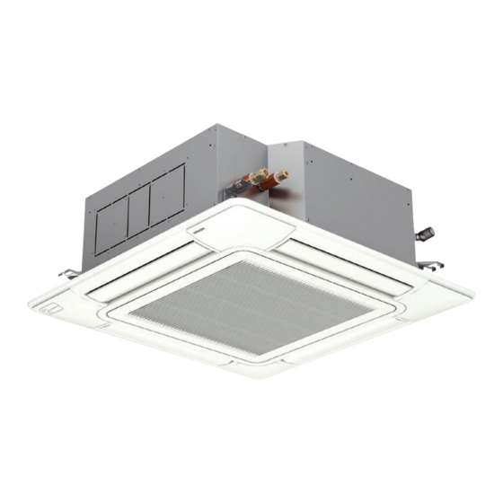
- Page 1 – INSTALLATION AND OPERATION MANUAL – INDOOR UNITS SYSTEM FREE 4-way cassette MODELS RCI-(1.0-6.0)FSR1 PMEN0649 rev.0 - 03/2023...
- Page 2 The English version is the original one; other languages are translated from English. Should any discrepancy occur between the English and the translated versions, the English version shall prevail. La versión en inglés es la original, y las versiones en otros idiomas son traducciones de la inglesa. En caso de discrepancias entre la versión inglesa y las versiones traducidas, prevalecerá...
- Page 3 усилия, за да се гарантира, че всички спецификации са коректни, но печатните грешки са извън обсега на контрола на Hitachi и Hitachi не може да носи отговорност за тези грешки. Aby společnost Hitachi mohla svým zákazníkům poskytovat nejnovější inovace, specifikace uvedené...
- Page 4 Hitachi nie ponosi żadnej odpowiedzialności. Specificațiile din acest manual pot fi modificate fără notificare prealabilă, pentru ca Hitachi să poată pune la dispoziția clienților noștri ultimele inovații. Deși depunem toate eforturile pentru a ne asigura că...
-
Page 5: Table Of Contents
Contents General information .....................4 Name of parts .....................10 Indoor unit installation ..................12 Refrigerant piping ....................20 Drain piping ......................23 Electrical wiring ....................27 Remote controller operation ................33 Maintenance.......................36 PMEN0649 rev.0 - 03/2023... - Page 6 General Index 1. General information ....................4 1.1 General notes ....................5 1.2 Product guide ....................5 1.2.1 Prior check ....................5 1.2.2 Classification of indoor unit models ............5 1.3 Safety .........................6 1.3.1 Symbols used ...................6 1.3.2 Additional information about safety ............7 1.4 Important notice ....................8 2. Name of parts ......................10 2.1 RCI-(1.0-6.0)FSR1 .....................11 3. Indoor unit installation...
- Page 7 6. Electrical wiring ......................27 6.1 General information ..................28 6.2 Electrical wiring connection for indoor unit ...........29 6.3 Settings of DIP Switches .................30 7. Remote controller operation ..................33 7.1 High speed setting function ................34 7.2 Circulation function at heating thermo-off .............34 7.3 Motion sensor function ...................34 7.4 Setting the filter indication interval ..............35 7.5 Individual louver setting ..................35 8. Maintenance...
-
Page 8: General Information
General information 1.1 General notes ....................5 1.2 Product guide ....................5 1.2.1 Prior check ....................5 1.2.2 Classification of indoor unit models ............5 1.3 Safety .........................6 1.3.1 Symbols used ...................6 1.3.2 Additional information about safety ............7 1.4 Important notice ....................8 PMEN0649 rev.0 - 03/2023... -
Page 9: General Notes
This document may therefore have been subject to amendments during the life of the product. Hitachi makes every effort to offer correct, up-to-date documentation. Despite this, printing errors cannot be controlled by Hitachi and are not its responsibility. -
Page 10: Safety
1.3 Safety 1.3.1 Symbols used During normal air conditioning system design work or unit installation, greater attention must be paid in certain situations requiring particular care in order to avoid injuries and damage to the unit, the installation or the building or property. Situations that jeopardise the safety of those in the surrounding area or that put the unit itself at risk will be clearly indicated in this manual. -
Page 11: Additional Information About Safety
1.3.2 Additional information about safety DANGER • Hitachi is not able to foresee all the circumstances which may result in a potential danger. • Do not pour water in the indoor or outdoor unit. These products are fitted with electric components. If water comes into contact with electric components, this will cause a serious electric shock. -
Page 12: Important Notice
This air conditioner has been designed for standard air conditioning for human beings. For use in other applications, please contact your Hitachi dealer or service contractor. The air conditioning system should only be installed by qualified personnel, with the necessary resources, tools and equipment, who are familiar with the safety procedures required to successfully carry out the installation. - Page 13 There are detailed information about unit installation, service space, wiring diagrams, electrical connection, refrigerant charge, in the corresponding chapter, please read the corresponding chapter carefully before starting work on the installation. ◆ Motion sensor kit PS-MSK2 (optional) Do not install the motion sensor kit PS-MSK2 (optional) in the following places. It may cause misdetection, undetectable of motion or the deterioration of the motion sensor.
-
Page 14: Name Of Parts
Name of parts 2.1 RCI-(1.0-6.0)FSR1 .....................11 PMEN0649 rev.0 - 03/2023... -
Page 15: Rci-(1.0-6.0)Fsr1
2.1 RCI-(1.0-6.0)FSR1 Fan Motor Heat Exchanger Distributor Strainer Micro-Computer Control Expansion Valve Electrical box Refrigerant Gas Pipe Connection Refrigerant Liquid Pipe Connection Drain Pipe Connection Drain Discharge Mechanism Float Switch Drain Pan Rubber Plug for Drain Air Panel P-N23NA2 Air Inlet Grille Air Filter Air Outlet Air Inlet... -
Page 16: Indoor Unit Installation
Indoor unit installation 3.1 Unit installation ....................14 3.1.1 Factory-Supplied Accessories ..............14 3.1.2 Initial Check ..................15 3.1.3 Installation .....................16 PMEN0649 rev.0 - 03/2023 PMEN0649 rev.0 - 03/2023... - Page 17 DANGER • Check to ensure that the accessories are packed with the indoor unit. • Do not install the indoor units outdoors. If installed outdoors, an electric hazard or electric leakage will occur. • Consider the air distribution from each indoor unit to the space of the room, and select a suitable location so that uniform air temperature in the room can be obtained.
-
Page 18: Unit Installation
3.1 Unit installation 3.1.1 Factory-Supplied Accessories Accessory Qty. Purpose Pattern Board (Carton Board) For adjusting space of false ceiling opening and Checking Scale position of the unit (cut and take out it from the carton board) Washer with Insulation Material (M10) For unit installation Washer (M10) Drain Hose... -
Page 19: Initial Check
3.1.2 Initial Check • Install the indoor unit with a proper clearance around it paying careful attention of installation direction for the piping, wiring and maintenance working space, as shown below. • Provide a service access door near the unit piping connection area on the ceiling. (mm) Piping Connection Service Access... -
Page 20: Installation
◆ Opening Of False Ceiling • Cut out the area for the indoor unit in the false ceiling and install suspension bolts, as shown below. Dimension of (mm) opening: 860 to 910 (Unit size) Holes 4-12 x 32 (for suspension bolt) (Dimension of suspension bolts) 4-Positions of... - Page 21 ◆ Mounting of Indoor Unit • Mount the nuts and the washers to the suspension bolts. Put the washer so that the surface with insulation faces downwards as shown below: (mm) Suspension bolts (field-supplied) Nut (field-supplied) Washer with insulation (accessory) Suspension bracket (attached indoor unit) Washer (accessory) Nut (field-supplied)
- Page 22 ◆ For ceiling already completed with panels Attach this side of the scale to the inner side of the opening of the ceiling Attach this side of the scale to the lower side of the unit Indoor Unit Indoor Unit Attach this side of the scale Ceiling Attach this side of the...
- Page 23 ◆ Sensing area for the motion sensor kit PS-MSK2 (optional) only as an accessory for air panel P-N23NA2 The sensing area for the motion sensor is shown in the figure below when applying the motion sensor with the air panel. Motion sensor Ø...
-
Page 24: Refrigerant Piping
Refrigerant piping 4.1 Piping connection ....................21 4.1.1 Piping Position ..................21 4.1.2 Size of piping connection ..............22 PMEN0649 rev.0 - 03/2023... -
Page 25: Piping Connection
4.1 Piping connection 4.1.1 Piping Position (mm) ø30 (Gas pipe) (Liquid pipe) Gas pipe connection Liquid pipe connection (mm) ø30 PMEN0649 rev.0 - 03/2023... -
Page 26: Size Of Piping Connection
4.1.2 Size of piping connection ◆ Piping size mm (in) Liquid piping Gas piping RCI-(1.0-2.0) Ø 6.35 (1/4) Ø 12.70 (1/2) RCI-(2.5-6.0) Ø 9.52 (3/8) Ø 15.88 (5/8) ◆ Thickness of Copper Pipes Ø (in) Ø (mm) Thickness (mm) 6.35 0.80 9.53... -
Page 27: Drain Piping
Drain piping 5.1 General information ..................24 5.2 Drain pipe connection ..................25 PMEN0649 rev.0 - 03/2023... -
Page 28: General Information
5.1 General information INCORRECT CORRECT Incorrect: Upward Slope Min. 100mm 1/25 to 1/100 (higher as possible) Vinyl chloride pipe (VP25) Down-Slope This drain piping shall be separating from others pipes Common drain piping (Min.VP30) Drain piping of unit side Incorrect: Rising Part (Down slope from rising part) C A U T I O N •... -
Page 29: Drain Pipe Connection
NOTE Pay attention to the thickness of the insulation when the left side piping is performed. If it is too thick, piping can not be installed in the unit. 5.2 Drain pipe connection 1 The position of the drain pipe connection is shown below. (mm) 2 Prepare a polyvinyl chloride pipe with a 32mm outer diameter. - Page 30 8 Insulate the drain pipe after connecting the drain hose. Insulation (5T x 270 x 270) (accessory) Wrap up the drain hose completely to cover the hose band Hose band (accessory) NOTE If there is excessive clearance between the drain pipe connection and the drain hose, add a sealing material between both parts in order to fit and not deform the drain hose.
-
Page 31: Electrical Wiring
Electrical wiring 6.1 General information ..................28 6.2 Electrical wiring connection for indoor unit ...........29 6.3 Settings of DIP Switches .................30 PMEN0649 rev.0 - 03/2023... - Page 32 6.1 General information DANGER • Turn off the main power switch to the indoor unit and the outdoor unit before electrical wiring work or a periodical check is performed. • Check to ensure that the indoor fan and the outdoor fan have stopped before electrical wiring work or a periodical check is performed.
- Page 33 6.2 Electrical wiring connection for indoor unit 1 The electrical wiring connection for the indoor unit is shown below. Cord clamp Piping cover Wiring connection hole Wiring support plate Screw for wiring support plate under piping cover Electrical box PCB (Printed circuit board) Electrical box cover Screw (for electrical box cover) Transition wiring between indoor unit and outdoor unit...
- Page 34 6 Connect the wires between the indoor unit and the outdoor unit to the terminals in the electrical box. Earth terminal Electrical box Terminal board (TB1) Terminal board (TB2) Earth screw Power source cable 0.75 mm (1~ 230V 50Hz) Max. current: 5 A H-Link transmission wiring 0.75 mm Remote control switch cable 6.3 Settings of DIP Switches...
- Page 35 ◆ DSW3: Capacity code setting No setting is required. This dip switch is utilized for setting the capacity code which corresponds to the Horse Power of the indoor unit. Factory setting: DSW3 1.0 HP 1.5 HP 2.0 HP 2.5 HP 1 2 3 4 5 6 1 2 3 4 5 6 1 2 3 4 5 6...
- Page 36 ◆ DSW6 and RSW2: Unit number setting Setting is required. Factory setting: DSW6 RSW2 1 2 3 4 5 6 DSW6 and RSW2 can be set up to 63. Ex. Setting nº15 DSW6 RSW2 1 2 3 4 5 6 Nº...
-
Page 37: Remote Controller Operation
Remote controller operation 7.1 High speed setting function ................34 7.2 Circulation function at heating thermo-off .............34 7.3 Motion sensor function ...................34 7.4 Setting the filter indication interval ..............35 7.5 Individual louver setting ..................35 PMEN0649 rev.0 - 03/2023... - Page 38 Hitachi recommends PC-ARFP(1)E remote control in order to obtain the maximum RCI-(1.0-6.0) FSR1 performance. For detailed functions should be referred to remote control Installation and Operation Manual. 7.1 High speed setting function This function allow to set the air flow volume higher than normal air flow volume steps. It is for high height ceiling on site.
- Page 39 7.4 Setting the filter indication interval The FILTER interval indication on the remote control switch can be set in several intervals. Refer to remote control Installation and Operation Manual. 7.5 Individual louver setting The individual control setting for each louver is available with PC-ARFP(1)E remote control. Refered to remote control Installation and Operation Manual.
-
Page 40: Maintenance
Maintenance 8.1 Take out the filter ....................37 8.2 Clean the filter ....................37 8.3 Reset of filter indication ..................38 8.4 Safety and control device setting ..............38 PMEN0649 rev.0 - 03/2023... -
Page 41: Take Out The Filter
When the indication, “FILTER” is shown on the display of the remote control switch, take out the air filter according to the indicated steps for each unit. Do not operate the system without the air filter to protect the indoor unit heat exchanger against being clogged. -
Page 42: Reset Of Filter Indication
CAUTION Do not use hot water higher than approximately 40ºC. 2 Dry the air filter in the shade after shaking off moisture. 3 Do not use cleaner or other chemicals. 4 After the air filter is dried, attach and close correctly to the air inlet grille. 8.3 Reset of filter indication After cleaning the air filter, reset the filter sign according the remote control procedure. - Page 43 Johnson Controls-Hitachi Air Conditioning Spain, S.A.U. Ronda Shimizu, 1 - Políg. Ind. Can Torrella 08233 Vacarisses (Barcelona) Spain © Copyright 2023 Johnson Controls-Hitachi Air Conditioning Spain, S.A.U. – All rights reserved. PMEN0649 rev.0 - 03/2023 Printed in Spain...
Need help?
Do you have a question about the RCI-1.0FSR1 and is the answer not in the manual?
Questions and answers