Sign In
Upload
Manuals
Brands
Fuji Electric Manuals
Measuring Instruments
Time Delta-C FSV-2
Fuji Electric Time Delta-C FSV-2 Manuals
Manuals and User Guides for Fuji Electric Time Delta-C FSV-2. We have
2
Fuji Electric Time Delta-C FSV-2 manuals available for free PDF download: Instruction Manual
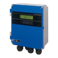
Fuji Electric Time Delta-C FSV-2 Instruction Manual (149 pages)
Ultrasonic flowmeter flow transmitter advanced type
Brand:
Fuji Electric
| Category:
Measuring Instruments
| Size: 4 MB
Table of Contents
Preface
2
Safety Precautions
3
Caution on Installation Location
5
Table of Contents
6
1 Product Outline
8
Overview
8
Measuring Principle
8
Checking Delivered Items
10
Check on Type and Specifications
11
Name and Function of each Part
12
2 Operation Preparation
13
Outline of Installation Procedure
13
3 Installation
14
Installation Location of Flow Transmitter
14
Installation of Flow Transmitter
15
Wall Mounting
15
Pipe Stand Mounting
15
Flow Transmitter Wiring
16
Cautions in Wiring
16
Applicable Wires
16
Treatment of Wiring Port
16
How to Connect to Terminal Block
18
Cable Treatment
18
How to Connect to Power Supply/Signal
19
Terminal Block
19
How to Connect to Communication Board and Temperature Input Board
20
Terminal
20
How to Attach Ferrite Cores
21
4 Parameters
22
Description of Display/Setting Unit
22
Display/Setting Unit
22
Description of Display/Setting Unit
23
Measurement Modes
24
Function Block Diagram
24
Definition of the Channels
24
Composition of Key Operation
25
1-Path/Energy Measurement Mode and 2- Path Mode
25
2-Pipe Mode
28
Parameter Initial Value List
31
Parameter Protection
35
Protection ON/OFF
35
Display Language
36
How to Select the Language
36
Switching Measurement Mode
37
Setting Measurement Mode and CH3
37
(Calculation Output)
37
Channel Number
38
Channel Designation
38
Specifications/Detector
39
Checking Piping Parameter
39
1-Path/Energy Measurement Mode and 2-Path Mode
39
2-Pipe Mode
40
Piping Parameter Setting Method
41
Zero Adjustment
44
Setting of Unit
45
Unit System
45
Flow Rate Unit
46
Flow Total Unit
47
Temperature Unit
48
Thermal Unit
49
Thermal Total Unit
50
Output Setting
51
Setting of Flow Rate Range
51
Flow Rate Range (Single Range)
51
Thermal Range (Single Range)
53
The Source of Analog Output
54
Analog Output at Error (Burnout)
55
Output Limit
56
Setting the Total (Actual)
57
Total Flow Pulse (Total Rate, Pulse Width)
57
Preset Value for Total Flow
59
Total Energy Pulse
60
Width)
60
Preset Value for Total Energy
61
TOTAL Mode
62
(Burnout)
63
Totalization Processing at Error
63
DO Output
64
Total Pulse Output
65
LCD Indication
66
Damping
67
Low Flow Rate Cutting
68
Application Operation of Parameter
69
Automatic 2 Ranges
69
Bi-Directional Range
71
Bi-Directional Auto 2 Range
73
Rate Limit
75
DO Output
77
FULL SCALE 2 Output
77
Alarm Output
78
Flow Switch
79
Total Switch
81
Over Output
82
Range over Output and Pulse Range
82
Output at the Minus Flow Direction
83
Cooling/Heating Mode Switching Output
84
Temperature Alarm
85
Calibrating the Measured Value
86
Setting the Operation Mode
87
Speed)
87
Energy Measurement
88
Settings for Energy Measurement
88
Mode Setting and Temperature Input
89
Signal
89
Conditioning)
90
Operation Mode
90
Calibrating the Temperature
92
Maintenance Mode
94
Copying the Parameters
94
Calibrating the Analog Output
95
Constant Current Output
96
Checking the Total Pulse Output Action
97
Checking the Status Output
98
Confirming the Input Temperature
99
Test Mode (Simulated Flow Rate Output)
100
Serial Transmission (RS-485)
102
Confirming the Software Version
104
Setting the ID no
104
Initializing Setting Parameters
105
LCD Backlight Setting
106
Advanced Settings
107
5 Mounting of Detector
109
Detector Mounting Procedure
109
Mounting of Detector
110
Image Figure of Mounting Dimension
110
Selection of Mounting Method
111
Mounting Method on the Pipe
111
6 Check and Maintenance
112
Daily Check
112
Periodic Inspection
112
Checking Zero Point
112
Reapplying Grease
112
How to Measure the Insulation Resistance
113
How to Replace the Fuse
114
How to Replace the LCD
115
Error and Remedy
116
Display Error
116
Checking the LCD/LED
116
Checking the LED Lit in Red
117
Checking the RAS Information
119
Displaying the Data in Maintenance Mode
121
Key Error
122
Error in Measured Value
123
Error in Analog Output
125
Error in Input Temperature
126
Checking Received Waveforms
127
How to Connect the Oscilloscope
127
Checking Sending/Receiving
128
Remedying a Hardware Fault
130
7 Appendix
131
Specifications
131
Outline Diagram
134
Parameter List
135
Piping Data
141
Advertisement
Fuji Electric Time Delta-C FSV-2 Instruction Manual (119 pages)
Ultrasonic flowmeter flow transmitter
Brand:
Fuji Electric
| Category:
Measuring Instruments
| Size: 5 MB
Table of Contents
Introduction
2
Safety Precautions
3
Caution on Installation Location
6
Table of Contents
7
1 Product Outline
9
Checking Delivered Items
9
Check on Type and Specifications
10
Name and Function of each Part
11
Flow Transmitter : FSV
11
Flow Transmitter : FSV
12
2 Installation and before Start of Operation of the Flow Transmitter
13
Outline of Installation Procedure
13
3 Installation
14
Installation Location of Flow Transmitter
14
Installation of Flow Transmitter
15
Wall Mounting
15
(Ip66))
15
Pipe Stand Mounting
15
Fsv
15
Wall Mounting
16
(Ip67))
16
Pipe Stand Mounting
16
Fsv
16
Flow Transmitter Wiring
17
Cautions in Wiring
17
Applicable Wires
17
Treatment of Wiring Port
17
Wiring to each Terminal
18
Flow Transmitter : FSV
18
Flow Transmitter : FSV
19
How to Connect to Terminal Block
20
Block for Signal
20
Cable Treatment
20
How to Connect to Power Supply/Terminal
20
How to Connect to Communication
21
Terminal Block
21
4 Parameter
22
Description of Display/Setting Unit
22
Flow Transmitter : FSV
22
Display/Setting Unit
22
Description of Display/Setting Unit
23
Composition of Key Operation
24
Parameter Initial Value List
29
Parameter Protection
31
Protection ON/OFF
31
Display Language
32
How to Select the Language
32
Specifications/Detector
33
Checking Piping Parameter
33
Piping Parameter Setting Method
34
Zero Adjustment
37
Setting of Unit
38
How to Set the Unit System
38
How to Set the Flow Rate Unit
39
How to Set the Total Unit
40
Output Setting
41
Setting of Flow Rate Range
41
Setting of Flow Rate Range (Single Range)
41
(Burnout)
43
Setting of Analog Output at Error
43
Output Limit
44
Setting the Total(Actual)
45
Setting the Total Pulse
45
Width)
46
Setting the Preset Value
47
TOTAL Mode
48
Determining How to Dispose of Total at Error (BURNOUT)
49
Setting the DO Output
50
How to Validate the Total Pulse Output
50
Setting the LCD Indication
52
Setting the Damping
53
Setting the Low Flow Rate Cutting
54
Application Operation of Parameter
55
Setting Automatic 2 Ranges
55
Setting the Bi-Directional Range
57
Setting the Bi-Directional Auto 2 Range
59
Rate Limit
61
Setting the DO Output
63
How to Validate Outputting the FULL
63
Scale 2
63
How to Validate the Alarm Output
64
Setting the Flow Switch
65
How to Validate the Total Switch
67
How to Validate the Range over Output and Pulse Range over Output
68
Direction Action
69
How to Validate the Output at the Minus
69
How to Compensate the Measurement
70
Value
70
Setting of the Operation Mode
71
Maintenance Mode
72
How to Calibrate the Analog Output
72
How to Set the Constant Current Output
73
How to Check the Action of Total Pulses
74
How to Check the Status Output
75
How to Validate the Test Mode
76
Flow Rate Output
76
How to Validate a Serial Transmission
78
How to Set the ID no
80
How to Confirm the Software Version
80
Initializing Setting Parameters
81
LCD Backlight Setting
82
How to Set the Detailed Setting
83
5 Mounting of Detector
85
Detector Mounting Procedure
85
Mounting of Detector
86
Image Figure of Mounting Dimension
86
Selection of Mounting Method
87
Mounting Method on the Pipe
87
6 Check and Maintenance
88
Daily Check
88
Periodic Inspection
88
Checking Zero Point
88
Reapplying Grease
88
How to Measure the Insulation Resistance
89
Flow Transmitter : FSV
89
Flow Transmitter : FSV
90
How to Replace the Fuse
91
Flow Transmitter : FSV
91
Flow Transmitter : FSV
92
How to Replace the LCD
93
Flow Transmitter : FSV
93
Flow Transmitter : FSV
94
Error and Remedy
95
Display Error
95
Checking the LCD/LED
95
Checking the LED Lit in Red
96
Checking the RAS Information
97
Displaying the Data in Maintenance Mode
98
Keying Is Abnormal
99
Error in Measured Value
100
Error in Analog Output
102
Checking Received Waveforms
103
How to Connect the Oscilloscope
103
Checking Sending/Receiving
104
Remedying a Hardware Fault
106
7 Appendix
107
Specifications
107
Outline Diagram
109
Ordering Information
110
Piping Data
111
Advertisement
Related Products
Fuji Electric FSC-1
Fuji Electric FSC-2
Fuji Electric FSC-3
Fuji Electric FSC-4
Fuji Electric FSS-1
Fuji Electric FSD-1
Fuji Electric FSJ
Fuji Electric FSX
Fuji Electric FSZ
Fuji Electric FSZ08
Fuji Electric Categories
Air Conditioner
Inverter
Measuring Instruments
Controller
Control Unit
More Fuji Electric Manuals
Login
Sign In
OR
Sign in with Facebook
Sign in with Google
Upload manual
Upload from disk
Upload from URL