Siemens SIRIUS M200D Manual
Industrial controls load feeders and motor starters
Hide thumbs
Also See for SIRIUS M200D:
- Operating instructions (4 pages) ,
- Manual (234 pages) ,
- Operating instructions (4 pages)

Related Manuals for Siemens SIRIUS M200D


Summary of Contents for Siemens SIRIUS M200D
- Page 1 Industrial Controls Load Feeders and Motor Starters SIRIUS Motor Starter M200D AS-Interface Standard Gerätehandbuch Manual Edition 08/2014 Answers for industry.
- Page 3 ___________________ M200D AS-Interface Standard Product description ___________________ Product family ___________________ Functions ___________________ Industrial Controls Mounting/Connecting ___________________ Configuring/assigning parameters SIRIUS motor starters ___________________ M200D AS-Interface Standard Commissioning ___________________ Diagnostics ___________________ Technical data Manual ___________________ Appendix ___________________ Bibliography ___________________ Correction sheet 08/2014 A5E02548958A/RS-AA/004...
- Page 4 Note the following: WARNING Siemens products may only be used for the applications described in the catalog and in the relevant technical documentation. If products and components from other manufacturers are used, these must be recommended or approved by Siemens. Proper transport, storage, installation, assembly, commissioning, operation and maintenance are required to ensure that the products operate safely and without any problems.
-
Page 5: Table Of Contents
Table of contents Product description ..........................9 What are M200D distributed motor starters? ................9 Fieldbus interfaces ........................11 1.2.1 AS-Interface ..........................11 Product family ............................13 M200D AS-Interface motor starters ..................13 Overview of the device functions .................... 14 Design concept ........................ - Page 6 Table of contents Short-circuit protection (circuit breaker/disconnecting means) ..........64 Communication ........................65 3.9.1 Communication paths ......................66 3.9.1.1 Communication path - Process image ................... 66 3.9.1.2 Communication path - Diagnostics ..................67 3.9.1.3 Communication path - Extended process image ..............68 3.9.1.4 Communication path - Parameter bits ...................
- Page 7 Table of contents Configuring/assigning parameters ....................... 109 Configuring ..........................109 AS-i profiles ........................... 109 5.2.1 ID1 code ..........................110 Configuring on the DP/AS-i Link Advanced ................110 Assigning parameters ......................115 5.4.1 Assigning parameters using AS-i parameter bits ..............115 5.4.2 Parameter overview ......................
- Page 8 Table of contents Appendix ............................. 159 Acyclic data transfer via CTT2 ..................... 159 A.1.1 Structure of the transfer protocol ..................160 A.1.2 Writing CTT2 data sets ......................161 A.1.3 Reading CTT2 data sets ...................... 163 A.1.4 Error codes with negative data set acknowledgment ............166 Data formats and data sets ....................
-
Page 9: Product Description
Product description What are M200D distributed motor starters? M200D motor starters are standalone devices with a high degree of protection (IP65) for distributed use near the motor. Depending on the order variant, they are available as: ● Direct starters, electromechanical (DSte) or electronic (sDSte) ●... - Page 10 Product description 1.1 What are M200D distributed motor starters? Integration of the motor starter into PROFINET, PROFIBUS and AS-Interface Figure 1-1 Possible fields of application of the M200D motor starter Motor starter manuals The following manuals are available for M200D motor starters: ●...
-
Page 11: Fieldbus Interfaces
Product description 1.2 Fieldbus interfaces Fieldbus interfaces 1.2.1 AS-Interface Overview The AS-Interface (actuator sensor interface, AS-i) is an open international standard for fieldbus communication between distributed actuators and sensors at the lowest control level. AS-i complies with the IEC 61158 / EN 50295 standards and was specifically designed for connecting binary sensors and actuators that comply with these standards. - Page 12 Product description 1.2 Fieldbus interfaces M200D AS-Interface Standard Manual, 08/2014, A5E02548958A/RS-AA/004...
-
Page 13: Product Family
Current range: 0.15 – 2 A and 1.5 – 9 A For a description, please refer to the M200D AS-Interface Basic Motor Starters (http://support.automation.siemens.com/WW/view/de/35016496) Manual. ● M200D AS-i STANDARD (parameter assignment via AS-i protocol or Motor Starter ES) Motor starter with thermistor motor protection + thermal motor model: –... -
Page 14: Overview Of The Device Functions
Product family 2.2 Overview of the device functions Overview of the device functions Differences between Basic and Standard starters Device functions M200D AS-i Basic M200D AS-i Standard Electromech./electronic Electromech. Electronic (DSte, RSte/sDSte, sRSte) (DSte, RSte) (sDSSte, sRSSte) Fieldbus interface ● ●... - Page 15 Product family 2.2 Overview of the device functions Device functions M200D AS-i Basic M200D AS-i Standard Electromech./electronic Electromech. Electronic (DSte, RSte/sDSte, sRSte) (DSte, RSte) (sDSSte, sRSSte) Additional functions Emergency start ● ● ● Self-test ● ● ● Factory settings ● ●...
-
Page 16: Design Concept
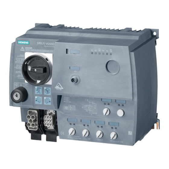
Product family 2.3 Design concept Design concept Connections and controls on the motor starter ① Disconnecting means (circuit breaker), can be locked ② Optical device interface ③ M12 AS-i connection ④ Diagnostic LEDs ⑤ 1 digital output M12 ⑥ 4 digital inputs M12 ⑦... -
Page 17: Operator Controls
Product family 2.3 Design concept 2.3.1 Operator controls The motor starter is equipped with the following operator controls: ① Key-operated switch (order variant) ② Keypad for manual local control (order variant) ③ Disconnecting means (circuit breaker) ① ② Integrated manual local control (key-operated switch and keypad ;... -
Page 18: Connections
Product family 2.3 Design concept 2.3.2 Connections Power connections ① Infeed for the 3 phases as well as the PE and N conductor via power connectors (HAN Q4/2 with ISO 23570 assignment) ② Connection of the motor via power connectors (HAN Q8/0) Control circuits ①... -
Page 19: Status Indicators
Product family 2.4 Internal design 2.3.3 Status indicators The following LEDs on the front of the starter indicate the device status: ① Indicators for the device status and communication ② Indicator for output OUT1 ③ Indicators for inputs IN1 ... IN4 At the inputs and outputs, only the right LED is active. - Page 20 Product family 2.4 Internal design Addressing the M200D AS-i STANDARD motor starter Slave 1 and Slave 2 occupy two AS-i addresses, such as 1A and 2A or 1A and 1B. In this way, A/B technology can be used to control up to 31 M200D AS-i STANDARD motor starters in a single AS-i segment.
- Page 21 Product family 2.4 Internal design Extended cyclic process image: CTT2 transfer is used for continually transferring 4 bytes between the AS-i master and slave, in both directions. Note In the AS-i system, this generally involves analog data; however, the term "transparent data" is more accurate for the M200D.
- Page 22 Product family 2.4 Internal design M200D AS-Interface Standard Manual, 08/2014, A5E02548958A/RS-AA/004...
-
Page 23: Functions
Functions Overview of the device functions Device functions for the M200D AS-i Standard starter Electromech. Electronic (DSte, RSte) (sDSSte, sRSSte) Fieldbus interface (Page 29) ● ● Control function reversing starter (Page 31) ○ ○ Control function soft starter (Page 32) —... -
Page 24: Introduction
Functions 3.2 Introduction Device functions for the M200D AS-i Standard starter Electromech. Electronic (DSte, RSte) (sDSSte, sRSSte) Additional functions Emergency start (Page 76) ● ● Self-test (Page 77) ● ● Factory settings (Page 78) ● ● Main power monitoring (Page 80) —... -
Page 25: Basic Functions / Parameters
Functions 3.3 Basic functions / parameters Self-protection The motor protects itself against fatal damage by means of the thermal motor model and temperature measurements for electronic switching elements. If the self-protection responds, ● the motor and the brake output are switched off immediately! ●... - Page 26 Functions 3.3 Basic functions / parameters Instructions ● In the M200D AS-i Standard motor starter, the rated operational current is preset at the factory to the maximum value. (For testing at startup without fieldbus and without previous parameterization) Note If the parameter bits of slave 1 are not changed during AS-i parameter assignment and no parameters are sent to the starter via process image or data set, the motor current is set to the highest value.
-
Page 27: Load Type (1-Phase/3-Phase Load)
Functions 3.3 Basic functions / parameters 3.3.2 Load type (1-phase/3-phase load) Here, you can specify whether the motor starter must protect a single-phase or a three- phase load. ● Asymmetry detection is deactivated in the case of a single-phase load, such as a single- phase AC motor! The single-phase load can be connected between any two paths of the motor starter for all mechanically switched motor starters. -
Page 28: Protection Against Voltage Failure
Functions 3.3 Basic functions / parameters 3.3.3 Protection against voltage failure You use this device parameter to specify whether or not the overload message must be retained after an electronics voltage failure: ● Overload ● No overload Settings Device parameter Default setting Setting range Protection against voltage failure... -
Page 29: Fieldbus Interface
Functions 3.4 Fieldbus interface Fieldbus interface 3.4.1 Response to CPU/Master STOP This device parameter enables you to specify how the motor starter is to respond to CPU/Master STOP: ● Retain last value: The PIO is retained. ● Switch substitute value: Substitute value = 0 Note This is only relevant in "automatic"... -
Page 30: Wait For "Parameter" Startup Data Set
Functions 3.4 Fieldbus interface Reference For more information, refer to the documentation for your AS-i master. Settings Device parameter Default setting Setting range Group diagnostics enable block • enable • 3.4.3 Wait for "Parameter" startup data set The user sets this parameter bit during configuration using STEP 7. It tells the motor starter if a data set will be transferred. -
Page 31: Motor Control
Functions 3.5 Motor control Motor control 3.5.1 Control function reversing starter Description This control function allows the motor starter to control the direction in which motors rotate. Simultaneous activation of both directions of rotation is prevented by the internal logic. Delayed switching from one direction of rotation to the other is implemented by means of the lock-out time. -
Page 32: Control Function Soft Starter
Functions 3.5 Motor control Messages and actions Message Action Motor CCW Motor runs with CCW rotation. Lock-out time active ON command suppressed in opposite direction. 3.5.2 Control function soft starter Description Soft starters function according to the phase angle control principle. You can specify soft starting and soft run-down using a settable voltage ramp. - Page 33 Functions 3.5 Motor control Soft run-down on motor starters with mechanical braking In parallel with soft run-down, motor starters with mechanical braking offer the following control options with the parameter "brake holding time on stopping": ● Brake holding time on stopping = 0: Motor voltage V is reduced to the stopping voltage during the run-down time.
- Page 34 Functions 3.5 Motor control Start time During the parameterized starting time, the motor terminal voltage is increased linearly from the starting voltage to the full line voltage. A setting of 0s means that the motor is switched on with a voltage ramp of 100 milliseconds to reduce the peak inrush current. Run-down time During the parameterized run-down time, the motor terminal voltage is reduced linearly from the line voltage to the stopping voltage.
- Page 35 Functions 3.5 Motor control Stopping voltage The stopping voltage is the final value of the voltage ramp for soft run-down. The voltage ramp is run to the stopping voltage and then switched off. Current limit value With the startup modes "Current limiting" and "Voltage ramp + current limiting", the motor current is limited to a maximum value during starting.
-
Page 36: Brake Output
Functions 3.5 Motor control 3.5.3 Brake output Description A motor-mounted mechanical disk or spring-loaded brake is used to brake the motor. The brake is controlled via the brake output. Typical circuit diagram The following circuit diagram illustrates the mechanical braking procedure with a 180 V DC brake output: Circuit diagram Motor connection plug... - Page 37 Note With both brake output versions, the electronic switching element is located on the AC side. Please refer to the technical data of the brake (e.g. Catalog D87.1 "SIEMENS MOTOX Geared Motors") for the resulting application time of the brake.
- Page 38 Functions 3.5 Motor control Brake holding time on stopping Note Only active if an OFF switching command is present for the brake and the motor simultaneously. This device parameter causes delayed tripping of the brake output compared to the motor. It also works in the event of a PLC failure.
-
Page 39: Motor Protection
Functions 3.6 Motor protection Motor protection 3.6.1 Thermal motor model Description The approximate temperature of the motor is calculated using the measured motor currents and device parameters "Rated operating current" and "Tripping class". This indicates whether the motor is overloaded or functioning in the normal operating range. Response to overload - thermal motor model You use this device parameter to specify how the motor starter is to respond in an overload situation:... - Page 40 Functions 3.6 Motor protection Trip class The trip class (CLASS) specifies the maximum time within which a protective device must trip from a cold state at 7.2x the current setting (motor protection to IEC 60947). The tripping characteristics represent this time to disengagement as a function of the tripping current. Figure 3-4 Tripping characteristics Note...
- Page 41 Functions 3.6 Motor protection Note Deactivation rule To guarantee motor protection, the trip class cannot be deactivated in the event that the temperature sensor is deactivated (= CLASS OFF). See also Data plausibility check (Page 73). Note Parameter dependence of control function soft starter If "direct"...
- Page 42 Functions 3.6 Motor protection Idle time The idle time is the time specified for cooling after tripping under normal operating conditions; that is, not in the case of overload tripping. Once this time has expired, the thermal memory of the motor starter is deleted. A cold restart can be carried out.
- Page 43 Functions 3.6 Motor protection Settings Device parameter Default setting Setting range Response to overload - thermal Trip without restart Trip without restart • motor model Trip with restart • Warning • Trip class CLASS 10 CLASS 5 (10a) • CLASS 10 •...
-
Page 44: Temperature Sensor
Functions 3.6 Motor protection Messages and actions Message Action Thermal motor model deactivated No motor protection via thermal motor model; motor protection required by means of temperature sensor. Thermal motor model - overload Dependent on parameterization Overload tripping Trip (overload pending) Idle time active The motor is reset on expiry of the idle time Cooling time active... - Page 45 Functions 3.6 Motor protection Temperature sensor You can activate or deactivate this parameter depending on whether or not a temperature sensor is installed in the motor. Two types of temperature sensor are supported: ● Thermoclick. This is a switch that opens at a certain winding temperature. ●...
- Page 46 Functions 3.6 Motor protection Settings Device parameter Default setting Setting range Response to temperature sensor Trip without restart Trip without restart • overload Trip with restart • Warning • Temperature sensor Deactivated Deactivated • Thermoclick • PTC type A • Temperature sensor monitoring •...
-
Page 47: System Monitoring
Functions 3.7 System monitoring System monitoring 3.7.1 Current limits Description The motor current and current limit values can be used to determine different system statuses: System status Current value Protection by Motor operates more sluggishly, Current is higher or lower than Current limit values e.g. - Page 48 Functions 3.7 System monitoring Upper/lower current limitYou can enter an upper and/or lower current limit. Example: ● "Viscosity of mixed mass is too high"; that is, the upper current limit has been overshot. ● "No load because drive belt is broken"; that is, the lower current limit has been undershot. Note The current limits are not activated until the class time expires, e.g.
- Page 49 Functions 3.7 System monitoring Blocking protection principle in run-up phase: The figure below shows the principle of blocking protection during the run-up phase; that is, the interaction between the blocking current and blocking time: Figure 3-6 Blocking protection principle Blocking protection principle after run-up phase Following the run-up phase, blocking protection behaves as follows during uninterrupted duty: ●...
- Page 50 Functions 3.7 System monitoring Settings Device parameter Default setting Setting range Response to residual current detection Trip Trip • Warning • Response to current limit violation Warning Warning • Trip • Lower current limit 18.75% 18.75 to 100% of I •...
-
Page 51: Asymmetry Monitoring
Functions 3.7 System monitoring 3.7.2 Asymmetry monitoring Description Three-phase induction motors respond to slight asymmetries in the supply voltage with a higher asymmetric current consumption, which causes the temperature in the stator and rotor windings to increase. In this case, the M200D motor starter protects the motor against overload by shutting it down. -
Page 52: Inputs
Functions 3.7 System monitoring Messages and actions Message Action Asymmetry detected Dependent on parameterization Asymmetry tripping Trip (asymmetry exists) 3.7.3 Inputs Description Using the "Inputs" device function, the motor starter can carry out different actions that you can parameterize whereby the signals at the digital inputs are evaluated. You can connect the inputs directly to sensors (PNP) (2 and 3-wire system). - Page 53 Functions 3.7 System monitoring Input function Figure 3-7 Overview of input parameters Input signal extension A short input signal can be extended compared to the actual input signal with the help of this parameter. This enables reliable transfer to the controller (compensation of bus transfer times and processing time in the controller).
- Page 54 Functions 3.7 System monitoring Input n level You use this device parameter to specify the input logic: ● Normally closed contact ● Normally open contact Note If you specify "Input n action": "Emergency start", "Motor CW", "Motor CCW", and "Trip reset", you can only program "Input n level"...
- Page 55 Functions 3.7 System monitoring Input n action Level Signal Mode Description No action NO/NC n-ret./ret. Trip without restart NO/NC n-ret./- Causes the motor and brake to trip. • Must be acknowledged once the cause of • tripping has been rectified (initial status). Trip with restart (auto NO/NC n-ret./-...
- Page 56 Functions 3.7 System monitoring Input n action Level Signal Mode Description Motor CW NO/- n-ret./ret. Manual local The motor starter must be in "manual local" • mode for these actions. Motor CCW NO/- n-ret./ret. Manual local (RSte/sRSSte only) The device parameters of the braking operation •...
- Page 57 Functions 3.7 System monitoring Quick stop ● The motor and brake output are switched off without a group fault. ● "Quick stop" has priority over "Motor CW" and "Motor CCW". ● The input action responds to the active edge of the input signal, which means that deactivation is possible when the static input signal "Quick stop"...
- Page 58 Functions 3.7 System monitoring Example 2: Digital input 1 signal = non-retentive/level-triggered (default setting) ① The motor is switched on and off by "Motor CW". ② The motor is switched on by "Motor CW", then switched off by the level at digital input 1 (parameterized with input action 1 = Quickstop).
- Page 59 Functions 3.7 System monitoring Settings Device parameter Default setting Setting range Input signal extension 0 ms 0 to 200 ms (Motor Starter ES) Increment: 10 ms Input signal delay 10 ms 10 to 80 ms (Motor Starter ES) Increment: 10 ms Input 1 level Normally open Normally closed contact...
-
Page 60: Outputs
Functions 3.7 System monitoring Messages and actions Message Action Input 1 Dependent on parameterization Input 2 Dependent on parameterization Input 3 Dependent on parameterization Input 4 Dependent on parameterization Input tripping Trip Input tripping - end position CW rotation Tripping (must be acknowledged with Motor OFF) Input tripping - end position CCW rotation Input control... - Page 61 Functions 3.7 System monitoring Output n action Different parameterizable actions can be triggered when an output signal is present. Settings Device parameter Default setting Setting range Output 1 level Non-inverted Non-inverted • Inverted • Output 1 signal Continuous signal Continuous signal •...
-
Page 62: Connector Monitoring
Functions 3.7 System monitoring 3.7.5 Connector monitoring The motor starter monitors whether the infeed connector on the line side of the motor starter is plugged in. Connector monitoring is implemented by means of an input activated via a jumper between pins 11 and 12, which informs the motor starter that the connector is plugged in. -
Page 63: Motor Connector
Functions 3.7 System monitoring Connector monitoring Line-side connector monitoring can be deactivated. Response when connector removed You use this device parameter to determine how the motor starter is to respond when the connector is removed: ● Group fault ● Group fault only after ON command ●... -
Page 64: Short-Circuit Protection (Circuit Breaker/Disconnecting Means)
Functions 3.8 Short-circuit protection (circuit breaker/disconnecting means) Short-circuit protection (circuit breaker/disconnecting means) Description The motor starter is equipped with an integrated circuit breaker for short-circuit protection to ensure that the system is safe and to protect personnel. Short-circuits between one phase and ground (= ground fault) as well as between two phases are monitored. -
Page 65: Communication
Functions 3.9 Communication Communication Description Communication is a higher-level device function comprising a number of sub-functions: ● Mode monitoring ● Fieldbus interface ● Commands ● Data plausibility check ● Messages output M200D AS-Interface Standard Manual, 08/2014, A5E02548958A/RS-AA/004... -
Page 66: Communication Paths
Functions 3.9 Communication 3.9.1 Communication paths 3.9.1.1 Communication path - Process image The cyclic process image PII/PIO with 6I/4O is made up of: ● Slave 1: 2I/1O ● Slave 2: 4I/3O Note The cyclic process image occupies 2 addresses in the PLC: Slave 1: 2I/1O and Slave 2: 4I/3O M200D AS-Interface Standard Manual, 08/2014, A5E02548958A/RS-AA/004... -
Page 67: Communication Path - Diagnostics
Functions 3.9 Communication 3.9.1.2 Communication path - Diagnostics The AS-i master enters the value of the I/O fault bit (S1) on the slave status tab in the list of I/O faults (LPF) that have been signaled. The PLC can read out this list using the "GET_LPF" command and then return a specific diagnostic value from the slave (see Diagnostics via parameter channel) (Page 137)). -
Page 68: Communication Path - Extended Process Image
Functions 3.9 Communication 3.9.1.3 Communication path - Extended process image CTT2 transfer is used for transferring serial data sets between the AS-i master and slave. Dependent on configuration, the M200D AS-i Standard always differentiates between two possible mechanisms: 1. Transfer of the "extended process image" of 4 bytes. In the description of the AS-i system, this mechanism is used to transfer analog data. -
Page 69: Communication Path - Parameter Bits
Functions 3.9 Communication 3.9.1.4 Communication path - Parameter bits The parameter bits (P bits) are used to control both startup characteristics and operation of the slave. The P bits are activated by default in HW Config. In the user program, you can choose between continual (cyclic) transfer and transfer on request. -
Page 70: Mode Monitoring
Functions 3.9 Communication 3.9.2 Mode monitoring Data channels M200D motor starters have 3 different data channels: ● Local optical device interface (for hand-held device/Motor Starter ES) ● Control with local control station in "manual local" mode – Using integrated manual local control (key-operated switch + keypad, order variant) –... - Page 71 Functions 3.9 Communication The following message bits in diagnostics data set DS 200 clearly indicate which control source currently has control priority: ● Automatic mode ● Manual mode local – Integrated manual local control controls – Input controls ● Connection abort in manual mode Automatic Manual Control priority...
-
Page 72: Commands
Functions 3.9 Communication 3.9.3 Commands Commands and their meaning Using the commands, you can instruct the motor starter to perform specific actions. You can use the Motor Starter ES configuration software or command data set DS 93 (Page 172) to send the following commands to the motor starter: Command Meaning... -
Page 73: Data Plausibility Check
Functions 3.9 Communication 3.9.4 Data plausibility check Description The motor starter checks all incoming parameters to ensure that they are valid and plausible. If parameters are incorrect: ● During a startup procedure (after Power ON), the messages "Group fault" and "Invalid parameter value"... -
Page 74: Messages Output
Functions 3.9 Communication 3.9.5 Messages output Message Meaning General messages Ready (automatic) Device can be controlled via BUS • Automatic mode • No fault • Group fault At least one fault is set. Group warning At least one warning is present. Process image error The process image of the outputs contains an illegal bit combination, e.g. -
Page 75: Logbook
Functions 3.10 Logbook 3.10 Logbook Description The logbook contains a chronological list of triggering operations, device errors, and events, which are assigned a time stamp and can be used to create a log. The log is stored internally so that the causes can be evaluated at a later stage. Note You require Motor Starter ES for this function. -
Page 76: Emergency Start
Functions 3.11 Emergency start 3.11 Emergency start Description An emergency start enables a restart to be carried out in spite of an internal trip command. An emergency start can be carried out if ● An ON switching command is present for the motor. The motor is switched on despite the fact that the cause of a trip is still present. -
Page 77: Trip Reset
Functions 3.12 Trip reset 3.12 Trip reset Trip reset acknowledges all the errors/faults that are currently present in the starter and that can be acknowledged. An error/fault can be acknowledged if its cause has been rectified or if it is no longer present. The trip reset can be triggered by: ●... -
Page 78: Factory Settings
Functions 3.14 Factory settings Self-test error If an error occurs, the "DEVICE" LED lights up red. The error can only be acknowledged by switching the device off and then on again. If the error is still present, the self-test will return an error again when the device is switched on. - Page 79 Functions 3.14 Factory settings Restoring factory settings You can restore the factory settings as follows: ● With the "Factory setting" command (using data set 93 or Motor Starter ES). This is only possible if "Manual" mode is set and the switching elements are deactivated. ●...
-
Page 80: Main Power Monitoring
Functions 3.15 Main power monitoring Messages and actions Messages Meaning Factory settings restored All parameters now again have the values set at the factory. Message bits that can be deleted with trip reset Note Parameters that are transferred via the expanded process image (if activated) overwrite the factory settings again. -
Page 81: Electronic/Mechanical Switching
Functions 3.16 Electronic/mechanical switching 3.16 Electronic/mechanical switching Electronic switching The motor starter controls the motor (two phases) with thyristors. Phase L1 is not switched but is instead looped through from the 400 V power connection to the motor connection via the integrated disconnecting means. -
Page 82: Cold Run
Functions 3.17 Cold run 3.17 Cold run Description This function enables activation of the motor without main power supply. The motor starter responds here as if the main power supply were connected to the system. Thus, in the commissioning phase, for example, the relevant control commands are accepted from the controller and the relevant messages are sent. -
Page 83: Local Device Interface
Functions 3.18 Local device interface 3.18 Local device interface Description The local optical device interface can be used to connect the motor starter to a PC or hand- held device (order no.: 3RK1922-3BA00; RS 232 interface cable: 3RK1922-2BP00). This control source has the highest priority. To stop the fiber-optic cable for the device interface from getting dirty, it is located under the removable unit labeling plate. -
Page 84: Integrated Manual Local Control
Functions 3.19 Integrated manual local control 3.19 Integrated manual local control Integrated manual local control (ordering option) for the M200D motor starter involves a key- operated switch and a keypad with four pushbuttons. Key-operated switch Figure 3-12 Key-operated switch The key-operated switch can be set to three different positions. Position Meaning Function... - Page 85 Functions 3.19 Integrated manual local control Keypad The keypad has four pushbuttons arranged in a square. Note They are only active when the key-operated switch is set to manual mode. Figure 3-13 Keypad Pushbutton Meaning Function Continuous The mode switches every time you press this pushbutton (continuous / jog). operation / jog mode "Continuous"...
- Page 86 Functions 3.19 Integrated manual local control Note If the "CW rotation" and "CCW rotation" pushbuttons are pressed simultaneously, this is classed as an operation fault. A function cannot be restarted. A function that is being executed is interrupted (the starter shuts down). A function cannot be restarted until both pushbuttons have been released.
-
Page 87: Mounting/Connecting
Mounting/Connecting Mounting 4.1.1 Installation rules DANGER Hazardous voltage Can Cause Death, Serious Injury, or Property Damage Before starting work, disconnect the system and devices from the power supply. Simple installation The distributed M200D AS-i motor starter is designed as a complete device that is easy to install. -
Page 88: Derating
Mounting/Connecting 4.1 Mounting 4.1.2 Derating What is derating? Derating allows devices to be used even in harsh operating conditions by selectively restricting the output capacity. Derating factors When M200D AS-i motor starters are operated under harsh conditions, the following factors must be taken into account: ●... - Page 89 Mounting/Connecting 4.1 Mounting Derating diagrams You can use the following diagrams to determine the derating factors for horizontal, vertical, or flat mounting. ① DSte, RSte, sDSSte, sRSSte with bypass in "soft start" startup mode (from 7 A) ② sDSSte, sRSSte with bypass in "direct" startup mode (from 7 A) ③...
- Page 90 Mounting/Connecting 4.1 Mounting ① DSte, RSte, sDSSte, sRSSte with bypass in "soft start" startup mode (from 7 A) ② sDSSte, sRSSte with bypass in "direct" startup mode (from 7 A) ③ sDSSte, sRSSte without bypass in startup mode "Direct" and "Soft start" Figure 4-3 Derating for vertical mounting ①...
- Page 91 Mounting/Connecting 4.1 Mounting Motors with a high efficiency and high motor starting currents High starting currents may have to be taken into consideration when using motor starters on high-efficiency motors. Motor starters are designed for motors with a maximum 8-fold starting current in accordance with IEC 60947-4-2.
-
Page 92: Installing The Protection Guards
Mounting/Connecting 4.1 Mounting 4.1.3 Installing the protection guards Protection guard (accessory) NOTICE The protection guards are designed for a maximum load of 10 kg. To prevent mechanical damage to the motor starter cables and connections, you can install protection guards on the side and top (order no.: 3RK1911-3BA00). To secure the protection guards, the angled ends can be used as clamping bolts, which are secured in the device base by means of eccentric elements. -
Page 93: Installing The Motor Starter
Mounting/Connecting 4.1 Mounting 4.1.4 Installing the motor starter Carry out the following steps to install the motor starter: Step Description Find a flat surface for mounting the device. Drill four holes for the screws. Secure the motor starter using four screws (M5). If necessary, use plain washers and spring washers. -
Page 94: Setting The As-I Address
Mounting/Connecting 4.1 Mounting 4.1.6 Setting the AS-i address Unique addressing In the factory setting, an I/O module (slave) has the address 0. It is detected by the master as a new slave that has not yet been addressed and, in this condition, has not yet been integrated in standard communication/data exchange. - Page 95 Mounting/Connecting 4.1 Mounting Offlline addressing with the addressing unit The motor starter is addressed via the AS-i connection socket. Note When assigning the address via the addressing unit, unscrew the encoders (sensors) from the digital inputs to prevent the addressing unit from being overloaded by their power consumption.
-
Page 96: Addressing The Motor Starter
Mounting/Connecting 4.1 Mounting 4.1.7 Addressing the motor starter The M200D AS-i Standard motor starter contains two separate logical AS-i slaves: Slave 1 and Slave 2. The diagram below illustrates the process by which these slaves are addressed. If both slaves are permanently assigned the address 0, from the AS-i master's point of view only the zero address of Slave 1 is visible. -
Page 97: Connecting
Connecting 4.2.1 Solution Partner More connection technology products can be found in "Siemens Solution Partners" (www.siemens.com/automation/partnerfinder) under "Distributed Field Installation System". The Solution Partner Program provides you with a complete range of connection methods in all the versions available from your preferred suppliers. This gives you the competitive edge with cost-effective cables in any length and design. -
Page 98: Prefabricating Power Cables
Mounting/Connecting 4.2 Connecting The following maximum current-carrying capacities apply for PVC power cables when installed, for example, in the cable duct (depending on the ambient temperature): Cross-section = 30 °C = 40 °C = 45 °C = 50 °C = 55 °C 1.5 mm 14 A 12.2 A... -
Page 99: Installing And Wiring Power Connectors
Mounting/Connecting 4.2 Connecting Consumer connection on the motor starter For the assignment of X2, see Power terminal (Page 100): ● A flexible Cu cable with 1.5 mm or 2.5 mm – Without brake control: 3 wire + PE – With brake control: 5 wire + PE –... -
Page 100: Power Terminal
Mounting/Connecting 4.2 Connecting 4.2.5 Power terminal Wiring X1 (power supply) and X2 (motor connection) The supply voltage is fed via power connector X1. The motor is supplied via power connector X2. Note When inserting the pin/female contact insert into the connector housing, make sure that the coding is positioned correctly. - Page 101 Mounting/Connecting 4.2 Connecting Power supply: Han Q4/2 socket (connection for X1) Socket Assignment Phase L1 Phase L2 Phase L3 Connector monitoring Connector monitoring PE (yellow/green) Note When you use the "connector monitoring" function, you have to connect pin 11 to pin 12 in the connector.
-
Page 102: Brake Output
Mounting/Connecting 4.2 Connecting Brake variants 400 V AC 230 V AC 180 V DC Note Please note the different pin assignment in the case of the operating voltages of the brake. 4.2.6 Brake output M200D motor starters can be equipped with an optional electronic brake control (order variant). - Page 103 Mounting/Connecting 4.2 Connecting The brake output for the M200D motor starter The brake voltage is fed to the motor together with the motor infeed via a joint cable (e.g. 6 x 1.5 mm WARNING Hazardous Voltage Can Cause Death or Serious Injury. The brake is only switched in a single phase.
-
Page 104: Inputs/Outputs
Mounting/Connecting 4.2 Connecting 4.2.7 Inputs/outputs Socket assignment The digital inputs and output are equipped with standard 5-pin M12 sockets (A coding): Assignment Input Output + 24 V (PWR+) 0 V (PWR-) 0 V (PWR AUX-) Input signal (IN x) Output signal (OUT 1) Functional ground (FE) Functional ground (FE) Note... -
Page 105: Digital Output Out1 (A Coding)
Mounting/Connecting 4.2 Connecting Pin assignment The following diagrams show examples of circuits (2 and 3-wire system): 2-wire system 3-wire system Note The supply voltage for the digital inputs is short-circuit proof. The current is limited to max. 200 mA. If a short-circuit or overload situation occurs in the sensor supply, the switching element (motor) and brake output are shut down and a group fault is output. -
Page 106: As-Interface
Mounting/Connecting 4.2 Connecting 4.2.8 AS-Interface Pin assignment Assignment AS-i+ PWR-AUX - AS-i– PWR-AUX + 4.2.9 Connection options for AS-Interface The different methods of connecting the motor starter to the AS-Interface bus cable and the 24 V DC auxiliary voltage are shown in the following table: Motor starter AS-i connection with U Plus M12 branch with integral... - Page 107 Mounting/Connecting 4.2 Connecting Connection examples for motor starters The installation guidelines for AS-Interface must always be observed: ● The maximum permissible current for all M12 connection cables is restricted to 4 A. The cross-section of these cables is just 0.34 mm². To connect the motor starter, you can use the M12 connection cables mentioned above as spur lines.
- Page 108 Mounting/Connecting 4.2 Connecting M200D AS-Interface Standard Manual, 08/2014, A5E02548958A/RS-AA/004...
-
Page 109: Configuring/Assigning Parameters
Configuring/assigning parameters Configuring Configuring involves integrating the motor starter in the overall system by assigning addresses and parameters. Master requirements The M200D AS-i Standard motor starter requires an AS-i master to AS-i spec. 3.0, with master profile M4. The table below lists AS-i masters that are M200D-compatible: Designation MLFB Remark... -
Page 110: Id1 Code
Configuring/assigning parameters 5.3 Configuring on the DP/AS-i Link Advanced 5.2.1 ID1 code You can use the ID1 code (Slave 2) to set the bit DI 1 assignment for the process image input (PII). ID1 code Meaning Explanation 7 (default) Motor on 0: OFF 1: ON (CW/CCW) Automatic... - Page 111 Configuring/assigning parameters 5.3 Configuring on the DP/AS-i Link Advanced Procedure 1. Click the Link Advanced module to open the AS-Interface module list. 2. Slave 1: To configure Slave 1, drag the "AS-i A/B Slave Universal" into this list from the list of modules in the DP-AS-i Link Advanced directory (e.g.
- Page 112 Configuring/assigning parameters 5.3 Configuring on the DP/AS-i Link Advanced 3. Change to the Configuration tab. 4. Click Selection... to open the slave selection box. Select the AS-i A/B Slave Universal by double-clicking it 5. Enter the following values for the AS-i profile: Field Value IO code:...
- Page 113 Configuring/assigning parameters 5.3 Configuring on the DP/AS-i Link Advanced 6. Then enter the AS-i parameter bits at Slave 1: P1 (bit 1): Extended process image The extended process image contains important parameters (see the table titled Parameter overview (Page 116)). Transfer can be activated or deactivated using P1. P2 (bit 2): In addition to the extended process image, parameters can be transferred acyclically via data sets (see the table titled Parameter overview).
- Page 114 Configuring/assigning parameters 5.3 Configuring on the DP/AS-i Link Advanced 8. Slave 2: To configure Slave 2, repeat steps 1 to 4. Please remember that the AS-i addresses must be different. 9. Enter the following values for the AS-i profile: Field Value IO code: 7 (B B B E)
-
Page 115: Assigning Parameters
CPU and AS-i master. GSD file on the Internet You can download the GSD file from the Internet (http://support.automation.siemens.com/WW/view/de/113630). The process for integrating the GSD file is described in detail in the manuals for the third- party controllers. -
Page 116: Parameter Overview
Configuring/assigning parameters 5.4 Assigning parameters 5.4.2 Parameter overview The table below provides an overview of all the M200D parameters and indicates which mechanism can be used to adjust each of the parameters. Device parameter Default setting Setting range Ext. PI DS 203 Motor Starter... - Page 117 Configuring/assigning parameters 5.4 Assigning parameters Device parameter Default setting Setting range Ext. PI DS 203 Motor Starter Brake release delay on - 2.5 to + 2.5 s — ✓ ✓ starting Increment: 0.01 s Brake holding time on 0 to 25 s —...
- Page 118 Configuring/assigning parameters 5.4 Assigning parameters Device parameter Default setting Setting range Ext. PI DS 203 Motor Starter Lower current limit 18.75% — ✓ ✓ 18.75 to 100% of I • 0% (= deactivated) • Increment: 3.125% Upper current limit 112.5% —...
- Page 119 Configuring/assigning parameters 5.4 Assigning parameters Device parameter Default setting Setting range Ext. PI DS 203 Motor Starter Output 1 level Non-inverted — ✓ ✓ Non-inverted • Inverted • Output 1 signal Continuous signal — ✓ ✓ Continuous signal • Flashing •...
-
Page 120: Process Data And Process Image
Configuring/assigning parameters 5.5 Process data and process image Process data and process image 5.5.1 Process image Definition of process image The process image is a component of the AS-i master system memory. At the start of the cyclic program, the signal states of the inputs are transferred to the process image of inputs. - Page 121 Configuring/assigning parameters 5.5 Process data and process image Process image for ID1 = 5: Byte/bit Process image Signal: 1 = HIGH, 0 = LOW DI 0 Ready (automatic) 0: Starter not ready for host/PLC 1: Starter ready to be operated via host DI 1 Group fault 0: No fault...
- Page 122 Configuring/assigning parameters 5.5 Process data and process image Output process image (PIO) The following table contains process data and a process image of outputs DO 0 to DO 3: Slave 2 Byte/bit Process image Signal: 1 = HIGH, 0 = LOW DO 0 Motor CW 0: Motor off...
-
Page 123: Extended Cyclic Process Image Via Ctt2
Configuring/assigning parameters 5.5 Process data and process image 5.5.2 Extended cyclic process image via CTT2 Extended cyclic process image of outputs (PIO) With M200D AS-i Standard motor starters, parameters are transferred from Slave 1 to the master on a continuous (cyclical) basis. This involves 4 bytes of data. These 4 bytes can be accessed from the user program in the same way as analog data is accessed. - Page 124 Configuring/assigning parameters 5.5 Process data and process image Extended cyclic process image of inputs (PII) With M200D AS-i Standard starters, Slave 1 returns diagnostics data, messages, and measured values to the master or CPU on a continuous (cyclical) basis. This involves 4 bytes of data.
-
Page 125: Motor Starter Es Software
Configuring/assigning parameters 5.6 Motor Starter ES software Motor Starter ES software Properties The Motor Starter ES diagnostics and commissioning tool (Version 2007 SP2 and higher) offers you the following: ● Structured, tool-based configuration of low-voltage switching devices ● Fast diagnostics ●... - Page 126 Configuring/assigning parameters 5.6 Motor Starter ES software M200D AS-Interface Standard Manual, 08/2014, A5E02548958A/RS-AA/004...
-
Page 127: Commissioning
Commissioning Requirements Parameter assignment The motor starter parameters are assigned during startup using the AS-i Standard procedure. Parameters can be modified and HMI (operator control and monitoring) tasks performed during operation, either via the bus and the acyclic mechanism or locally via the optical device interface. - Page 128 Commissioning 6.1 Requirements Software requirements Configuration software used Explanations Configuration software for the AS-i See the manual for the AS-i master master used Motor Starter ES Order no.: 3ZS1310-5CC10-0YA5 configuration software For parameter assignment and operator control and monitoring tasks using a local device interface (see online help) Commissioning requirements Prior activity For more information, see ...
-
Page 129: M200D Components
Commissioning 6.2 M200D components M200D components Minimum configuration The overview shows the components you need for operation: Figure 6-1 Minimum configuration of a motor controller Required components For this example, you need the following components: ● A higher-level controller (e.g. S7 series) ●... -
Page 130: Procedure
Commissioning 6.3 Procedure Procedure Commissioning procedure The following chart shows a logical, step-by-step commissioning procedure. Figure 6-2 Commissioning procedure M200D AS-Interface Standard Manual, 08/2014, A5E02548958A/RS-AA/004... -
Page 131: Diagnostics
Diagnostics Diagnostics data can be read from the motor starter in a number of different ways: ● Diagnostics on the device: – Status LEDs ● Diagnostics via AS-Interface: – S1 bit in the AS-i status register (AS-i slave status) – Parameter echo after AS-i command "Write_Parameter" P0 = 0 →... -
Page 132: Diagnostics With Leds
Diagnostics 7.1 Diagnostics with LEDs Diagnostics with LEDs 7.1.1 Statuses of the individual LEDs The following LEDs indicate the status of the motor starter: SF LED (possible colors: Red/OFF) Status Meaning Dependencies No error/fault — Device detects Device error: error/fault Current flowing with no ON command •... - Page 133 Diagnostics 7.1 Diagnostics with LEDs DEVICE LED (possible colors: Red/green/yellow/OFF) Status Meaning Cause Device not ready System error: No supply voltage for electronics or power supply • is < 18 V Green Device ready — Flashing green Device not starting up No startup parameters received Yellow Internal tripping...
- Page 134 Diagnostics 7.1 Diagnostics with LEDs STATE LED (possible colors: Red/green/yellow/OFF) Status Meaning Cause No control Switching element OFF Green Control Switching element ON by means of controller or HMI Flashing green Control and motor in soft Switching element ON startup/soft run-down with ramp operation (sDSSte and sRSSte only) Flickering green...
-
Page 135: Led Display Combinations
Diagnostics 7.1 Diagnostics with LEDs 7.1.2 LED display combinations You can detect certain faults/errors more accurately by looking at the combination of display statuses. Device status/mode SF LED STATE LED DEVICE LED Device status/mode Green Green Motor ON; no fault/error Green Motor ON;... - Page 136 Diagnostics 7.1 Diagnostics with LEDs System error/Warning SF LED STATE LED DEVICE LED System error/Warning Yellow Current not flowing despite ON command • (residual current detected) Internal tripping • No switching element supply voltage • External encoder supply short-circuit • No U •...
-
Page 137: Diagnostics Via Parameter Channel (Parameter Echo)
Diagnostics 7.2 Diagnostics via parameter channel (parameter echo) Diagnostics via parameter channel (parameter echo) Diagnostics (diagnostic message and diagnostic read procedure) In the PLC, you can tell whether a fault has occurred by looking at the "I/O fault bit" (S1) on the slave status tab. - Page 138 Diagnostics 7.2 Diagnostics via parameter channel (parameter echo) Call (motor starter M200D to AS-i master): Parameter echo - warnings (W) / messages (M) Decimal Message/Warning Priority No warning/message (M) No external startup parameters received (W) Main circuit breaker OFF (W) Residual current warning (M) Thermal motor model deactivated (W) Overload (W) Connector removed on line side...
-
Page 139: Sample Program
Alternatively, an ASI_Control function block (FB19) can be used for this task. You can find this block on the Siemens Service&Support pages (http://support.automation.siemens.com/WW/view/de/51678777). For a description of the ASi_3422 block, please refer to the manual for the AS-i master (DP- ASi Link, CP 343-2). -
Page 140: Diagnostics With The Addressing And Diagnostics Unit
Diagnostics 7.4 Diagnostics with the addressing and diagnostics unit In the parameters that have been read out, parameter P0 can now be changed as required. Sample program: // Parameters in memory byte MB4 // read messages/warnings from starter //: Bit P0 = 0 // or // read faults from starter: Bit P0 = 1 // trigger parameter echo... -
Page 141: Troubleshooting
Diagnostics 7.5 Troubleshooting Troubleshooting 7.5.1 Response to faults Description In some cases, the device can be set in such a way that it responds to faults by either issuing a warning or by tripping. Examples: "Response to asymmetry", "response to temperature sensor overload". -
Page 142: Acknowledging Faults
Diagnostics 7.5 Troubleshooting 7.5.2 Acknowledging faults Switching back on after device-internal tripping If the motor starter trips the switching elements automatically, it will not switch back on until: ● The fault has been rectified ● The fault has been acknowledged ●... -
Page 143: Technical Data
Technical data General technical specifications Location In the plant Wall mounted (near motor) Permissible mounting Vertical, horizontal, flat positions Degree of protection IP65 According to IEC 529 (DIN 40050) Type 12 According to UL Protection class IEC 60364-4-41 (DIN VDE 0100-410) Touch protection Finger-safe Degree of pollution... -
Page 144: Motor Starters
Technical data 8.2 Motor starters Note This product is designed for environment A (industrial environments). In household environments, this device can cause unwanted radio interference. The user may be required to implement appropriate measures in this case. Motor starters Motor starter version DSte/RSte sDSSte/sRSSte Installation dimensions in mm... - Page 145 Technical data 8.2 Motor starters Motor starter version DSte/RSte sDSSte/sRSSte Typ. switching times incl. internal signal - Closing delay 50 to 85 ms 25 / 105 ms processing at 0.85 to 1.1 x U - Opening delay 40 to 65 ms 35 / 35 ms Mechanical service life of contactor 30 million...
-
Page 146: Brake Control
Technical data 8.3 Brake control Brake control Brake version 400 V AC / 230 V 180 V DC Rated operating voltage AC 220 ... 600 V (-10% / +5%), 50 / 60 Hz Output voltage 0.45 x U e. g. 180 V DC at 400 V AC 215 V DC at 480 V AC Shutdown delay... -
Page 147: Output
Technical data 8.5 Output Output Number of digital outputs Cable length Shielded 30 m, max. Unshielded Short-circuit protection Electronic Response threshold > 0.7 A, typ. Limiting of inductive shutdown voltage Integrated freewheeling diode Lamp load 5 W, max. Switching capacity 0.5 A continuous current Controlling an AS-i digital input Not permissible... -
Page 148: Switching Frequency
Technical data 8.7 Switching frequency Switching frequency The switching frequency specifies how many switching cycles can be performed in one time unit (e.g. in 1 hour) with the switching device under normal operating conditions. If motors are switched too often, this causes the thermal motor model to respond. The maximum permissible switching frequency depends on the following operating data: ●... - Page 149 Technical data 8.7 Switching frequency The tables below provide an overview of the switching cycles/hour according to influencing factors. Direct and reversing starters, electronic (sDSte / sRSte) up to 5.5 kW Switching frequencies with active soft start function Switching cycles/hour for 3RK1325-6KS71-.AA. (0.15 A to 2 A) Mounting position Vertical Horizontal...
- Page 150 Technical data 8.7 Switching frequency Switching cycles/hour for 3RK1325-6LS71-.AA.(1.5 A to 12 A) Mounting position Vertical Horizontal Rated current I 4.5 A Ambient temperature 40 °C 50 °C 55 °C 40 °C 50 °C 55 °C Motor protection Class 5 (10a) On time = 30%, start 4 x I /1 s 250 On time = 70%, start 4 x I...
- Page 151 Technical data 8.7 Switching frequency Switching cycles/hour for 3RK1325-6LS71-.AA.(1.5 A to 12 A) Mounting position Vertical Horizontal Rated current I 5.8 A 4.5 A Ambient temperature 40 °C 50 °C 55 °C 40 °C 50 °C 55 °C Motor protection Class 5 (10a) On time = 30%, start 4 x I /1 s...
- Page 152 Technical data 8.7 Switching frequency Switching cycles/hour for 3RK1325-6LS71-.AA.(1.5 A to 12 A) Mounting position Vertical Horizontal Rated current I Ambient temperature 40 °C 50 °C 55 °C 40 °C 50 °C 55 °C Motor protection Class 5 (10a) On time = 30%, start 4 x I /1 s On time = 70%, start 4 x I /1 s...
- Page 153 Technical data 8.7 Switching frequency Switching cycles/hour for 3RK1325-6LS71-.AA.(1.5 A to 12 A) Mounting position Vertical Horizontal Rated current I 12 A 12 A 12 A 12 A 12 A 11 A Ambient temperature 40 °C 50 °C 55 °C 40 °C 50 °C 55 °C...
- Page 154 Technical data 8.7 Switching frequency Switching frequencies with deactivated soft start function (direct start) Switching cycles/hour for 3RK1325-6LS71-.AA.(1.5 A to 12 A) Mounting position Vertical Horizontal Rated current I Ambient temperature 40 °C 50 °C 55 °C 40 °C 50 °C 55 °C Motor protection Class 5 (10a)
- Page 155 Technical data 8.7 Switching frequency Switching cycles/hour for 3RK1325-6LS71-.AA.(1.5 A to 12 A) Mounting position Vertical Horizontal Rated current I 4.5 A Ambient temperature 40 °C 50 °C 55 °C 40 °C 50 °C 55 °C Motor protection Class 5 (10a) On time =30% (8 x I ) / 0.25 s 1300 240...
-
Page 156: Electrical Service Life Of Contactor
Technical data 8.8 Electrical service life of contactor Switching cycles/hour for 3RK1325-6LS71-.AA.(1.5 A to 12 A) Mounting position Vertical Horizontal Rated current I Ambient temperature 40 °C 50 °C 55 °C 40 °C 50 °C 55 °C Motor protection Class 5 (10a) On time =30 % (8 x I ) / 0.35 s On time =70 % (8 x I... - Page 157 Technical data 8.8 Electrical service life of contactor If mixed operation is available, i.e. if normal switching operation (breaking of rated operating current in accordance with utilization category AC-3) is mixed with occasional inching (breaking of the multiple rated operating current in accordance with utilzation category AC- 4), the service life of the contacts can be calculated approximately with the following formula: Contact service life for mixed operation in operating cycles Contact service life for normal operation (I...
-
Page 158: Dimension Drawing
Technical data 8.9 Dimension drawing Dimension drawing Figure 8-3 M200D AS-i motor starter without protection guard Figure 8-4 M200D AS-i motor starter with protection guard M200D AS-Interface Standard Manual, 08/2014, A5E02548958A/RS-AA/004... -
Page 159: Appendix
For more details, please refer to the manual for the DP/AS-i Link Advanced. If you are not using a SIEMENS AS-i master, please observe the information in the documentation for the master you are using. The way in which the data transfer process is structured differs according to the SIEMENS AS-i master in question. -
Page 160: Structure Of The Transfer Protocol
Appendix A.1 Acyclic data transfer via CTT2 The M200D AS-i Standard supports the following data sets: Write Device parameter DS 203 28 bytes Command data set DS 93 10 bytes Read Device diagnostics DS 200 9 bytes Measured values DS 201 7 bytes Statistical data DS 202... -
Page 161: Writing Ctt2 Data Sets
Appendix A.1 Acyclic data transfer via CTT2 A.1.2 Writing CTT2 data sets Job data in the send buffer Byte Master-dependent Meaning according to Value for Value for Meaning content AS-i spec. V3.0 (non- DS 93 DS 203 master-dependent) "Commands" "Parameters" Command —... - Page 162 Appendix A.1 Acyclic data transfer via CTT2 The figure below illustrates how a data set is written using the example of data set DS 203, "Parameters": Figure A-1 Writing CTT2 data sets ① The "Write a data set" command is provided in the send buffer. The first three bytes (command header) contain the command code (44 ), slave address, and number of CTT2 bytes.
-
Page 163: Reading Ctt2 Data Sets
Appendix A.1 Acyclic data transfer via CTT2 ② The CTT2 data set begins with the CTT2 command code (13 ), the data set number (CB = 203 ), and the data set length, followed by the data set bytes DS byte 0 to DS byte 27. The DP command interface for the AS-i master (DP/AS-i Link Advanced) accepts the data set bytes and forwards them to the addressed slave. - Page 164 Appendix A.1 Acyclic data transfer via CTT2 Response data in the receive buffer (error-free DS transfer) Byte Master-dependent Value for Value for Value for Value for Meaning content DS 200 DS 201 DS 202 DS 203 "Diagnostics" "Measured "Statistical "Parameters" values"...
- Page 165 Appendix A.1 Acyclic data transfer via CTT2 The figure below illustrates how a data set is read using the example of data set DS 200, "Diagnostics": Figure A-2 Reading CTT2 data sets ① The CPU sends the CTT2 data request (using command 44: CTT2 request_write) from the send buffer to the AS-i master via the command interface.
-
Page 166: Error Codes With Negative Data Set Acknowledgment
Appendix A.1 Acyclic data transfer via CTT2 ③ Within one second, the slave processes the job and sends the response to the AS-i master. ④ The AS-i master forwards the CTT2 data to the receive buffer of the CPU. The following responses are possible: : Error-free transfer : Transfer with error (CTT2 error) : Transfer with error (CTT2_command not supported) - Page 167 Appendix A.1 Acyclic data transfer via CTT2 DS error Error message Possible causes Remedial measures _Highbyte _Lowbyte From technology function (= access) Unknown data set n umber DS no. not supported by None, since the • • device device does not recognize this data set no.
-
Page 168: Data Formats And Data Sets
Appendix A.2 Data formats and data sets Data formats and data sets A.2.1 Data formats Properties The motor starter calculates a host of operating, diagnostic, and statistical data. Control data is transferred to the motor starter. Control data Data that is transferred to the motor starter, e.g. switching command motor CCW, trip reset, etc. - Page 169 Appendix A.2 Data formats and data sets Current values are ● Motor current I (6-bit current format) ● Phase currents I (8-bit current format) L1 max L2 max L3 max ● Last tripping current (9-bit current format) ● Maximum tripping current (9-bit current format) Statistical data on device service life ●...
- Page 170 Appendix A.2 Data formats and data sets Statistical data maximum pointers Maximum pointers are used for preventive diagnostics: The maximum measured value is stored in the device. The higher-level PLC can fetch the measured value at any time. The higher-level PLC can delete the measured value at any time. The following data is available in the form of a maximum pointer: ●...
-
Page 171: Data Sets
Appendix A.2 Data formats and data sets A.2.2 Data sets Byte arrangements When data longer than one byte is stored, the bytes are arranged as follows ("big endian"): M200D AS-Interface Standard Manual, 08/2014, A5E02548958A/RS-AA/004... -
Page 172: Writing Data Set 93 (Commands)
Appendix A.2 Data formats and data sets A.2.2.1 Writing data set 93 (commands) Byte.Bit Code Meaning 0x21 0x00 0x00 0x00 (1 byte) 0x00 Do not process any commands 0x01 Process command_1 0x02 Process command_1 and 2 0x03 Process command_1, 2, and 3 0x04 Process command_1, 2, 3, and 4 0x05... -
Page 173: Reading Data Set 200 (Device Diagnostics)
Appendix A.2 Data formats and data sets A.2.2.2 Reading data set 200 (device diagnostics) Byte.Bit Code Meaning Relevant User data (= technology data) Switch/Control Bit (1 = active) Ready (automatic) Motor CW Motor CCW .RS... only Switching element overload Switching element defective Emergency start active Group fault Group warning... - Page 174 Appendix A.2 Data formats and data sets Byte.Bit Code Meaning Relevant Bit (1 = active) Asymmetry detected Asymmetry tripping limit value overshot limit value undershot limit value tripping Residual current detected Residual current tripping Tripping due to motor blocking Bit (1 = active) Input 1 Input 2 Input 3...
-
Page 175: Reading Data Set 201 (Measured Values)
Appendix A.2 Data formats and data sets Byte.Bit Code Meaning Relevant Parameter Bit (1 = active) Parameter assignment active Invalid parameter value Parameters cannot be changed in ON state Parameters disabled CPU/master active No external startup parameters received Factory settings restored Free free BO: Brake output... -
Page 176: Reading/Writing Data Set 203 (Device Parameters)
Appendix A.2 Data formats and data sets A.2.2.5 Reading/writing data set 203 (device parameters) DS 203 (device parameters) We recommend initially reading out data set 203 from the motor starter with the current parameters, changing the corresponding parameters, and then rewriting these to the motor starter. - Page 177 Appendix A.2 Data formats and data sets Byte.Bit Parameter Value range/[code] Increment Default setting Relevant Response to [0] Warning — [1] Trip asymmetry [1] Trip 8.3 to 6 Connector [0]: Deactivated — [0] Deactivated monitoring [1]: Line side Free — —...
- Page 178 Appendix A.2 Data formats and data sets Byte.Bit Parameter Value range/[code] Increment Default setting Relevant 15.0 to 1 Output 1 level [0]: Non-inverted — [0] Non-inverted [1]: Inverted [2 to 3]: Reserved 15.2 to 5 Output 1 signal [0]: Permanent —...
-
Page 179: Order Numbers
Appendix A.3 Order numbers Order numbers A.3.1 M200D AS-i order numbers Order number structure (MLFB structure) Position Meaning 1 to 7 — — 3RK1325 – ⇓ ⇓ ⇓ ⇓ M200D AS-i Standard motor starter ⇓ ⇓ ⇓ 0.15 - 2.0 A ⇓... -
Page 180: M200D As-I Standard Motor Starters
Appendix A.3 Order numbers A.3.2 M200D AS-i Standard motor starters Type Current range Brake Manual Order number Switching operation Direct starter 0.15 to 2.0 A 3RK1325-6KS41-0AA0 electromechanical 400/230 V AC 3RK1325-6KS41-0AA3 DSte 180 V DC 3RK1325-6KS41-0AA5 With HMI 3RK1325-6KS41-2AA0 400/230 V AC With HMI 3RK1325-6KS41-2AA3 180 V DC... -
Page 181: Spare Parts/Accessories
Appendix A.3 Order numbers Type Current range Brake Manual Order number Switching operation Reversing soft starter 0.15 to 2.0 A 3RK1325-6KS71-1AA0 electronic 400/230 V AC 3RK1325-6KS71-1AA3 sRSSte 180 V DC 3RK1325-6KS71-1AA5 With HMI 3RK1325-6KS71-3AA0 400/230 V AC With HMI 3RK1325-6KS71-3AA3 180 V DC With HMI 3RK1325-6KS71-3AA5... - Page 182 Appendix A.3 Order numbers Motor cable Designation Order no. Motor connector for connection to M200D motor starters, consisting of socket shell, angled outlet, pin insert for HAN Q8/0, incl. cable gland 8 contact pins 1.5 mm 3RK1902-0CE00 6 contact pins 2.5 mm 3RK1902-0CC00 Motor connector for connection to motor, consisting of socket shell, straight outlet, socket insert for HAN 10e, incl.
- Page 183 Appendix A.3 Order numbers Further options Designation Order no. M200D safety bars 3RK1911-3BA00 RS 232 interface cable 3RK1922-2BP00 USB interface cable 6SL3555-0PA00-2AA0 Hand-held device for motor starters for local control 3RK1922-3BA00 Serial interface cable must be ordered separately Diagnostics and commissioning tool Motor Starter ES 2007 3ZS1310-5CC10-0YA5 AS-i addressing unit in accordance with AS-Interface version 2.1 Scope of supply: 3RK1904-2AB02...
- Page 184 Appendix A.3 Order numbers M200D AS-Interface Standard Manual, 08/2014, A5E02548958A/RS-AA/004...
-
Page 185: Bibliography
6GK1415-BA10; 6GK1415-2BA20 Document title Manual DP/AS-Interface Link 20E Entry ID 5281638 For products 6GK1415-2AA01 Topic M200D AS-i Basic motor starter Document title SIRIUS M200D AS-Interface Basic Manual Entry ID 35016496 For products 3RK1315-6KS41-..., 3RK1315-6LS41-... M200D AS-Interface Standard Manual, 08/2014, A5E02548958A/RS-AA/004... - Page 186 Bibliography Topic Addressing and analyzing Document title Addressing and Diagnosis Instrument for AS-i Modules Entry ID 48532283 For products 3RK1904-2AB02 Document title AS-Interface Analyzer Entry ID 26267998 For products 3RK1904-3AB01 Topic Control systems Document title S7-200 Automation System Entry ID 1109582 For products 6ES7214;...
-
Page 187: Correction Sheet
Have you noticed any errors while reading this manual? If so, please use this form to tell us about them. We welcome comments and suggestions for improvement. Fax response From (please complete): Name SIEMENS AG I IA CE MK&ST 3 Company/Department 92220 Amberg / Germany Address... - Page 188 Correction sheet M200D AS-Interface Standard Manual, 08/2014, A5E02548958A/RS-AA/004...
-
Page 189: Glossary
Glossary 24 V-NS DC Electronics supply voltage 24 V-S DC Switching element supply voltage AS-Interface (AS-i) The AS-Interface (or actuator/sensor interface; abbreviated to AS–i) is a connection system for the lowest process level in automation systems. Brake output Combined Transaction Type 2 (CTT2) Communication protocol on AS-Interface in accordance with Specification V3.0 for the transfer of large volumes of data (analog values, strings, etc.). - Page 190 Glossary Ground fault Fault whereby an external conductor comes into contact with ground or the grounded neutral point. Device master data GSDML The GSDML language is defined by the GSDML scheme. A GSDML scheme contains validity rules that allow you to check the syntax of a GSD file, for example. Manufacturers of IO devices can obtain GSDML schemes (in the form of scheme files) from PROFIBUS International.
- Page 191 Glossary N conductor (neutral conductor) EN 60947-1: A conductor connected to the center point or neutral point of the system and designed to transfer electrical energy. EN 60050-141: Conductor in a multi-phase cable that is connected to the neutral point N ) of a multi-phase combination. PE (protective conductor) ●...
- Page 192 Glossary Reversing starter Starting control function for the direction of rotation (CW / CCW). RSte Abbreviation for "reversing starter, electromechanical" sDSSte Abbreviation for "direct soft starter, electronic" sDSte Direct starter (electronic) Soft starter Function for starting/stopping motors smoothly. sRSSte Abbreviation for "reversing soft starter, electronic" sRSte Reversing starter (electronic) Step 7...
-
Page 193: Index
Index Connector monitoring, 62 Motor connector, 63 Power connector, 62 Control function Absolute current load, 88 Reversing starter, 31 Accessories, 13 Soft starter, 32 Acknowledging, 142 Cooling, 42 Acknowledgment, 74 Correction sheet, 187 Addressing, 94 CPU/Master STOP, 29 Addressing unit, 95, 140 Current limit, 47 Ambient temperature Ta, 88 Current limit value, 35... - Page 194 Index OFF / Reset, 84 Quick stop disable, 85 EMC resistance, 93 Emergency start, 76 Load type, 27 Logbook, 75 Factory settings, 78 Device errors, 75 Fault Events, 75 Acknowledging, 142 Triggering operations, 75 FE, 93 Fieldbus interface, 74 Functional ground, 93 Main power monitoring, 80 Manual mode local, 71 Master requirements, 109...
- Page 195 Temperature sensor, 46 Settings Connector monitoring, 63 Short-circuit protection Circuit breaker / disconnecting means, 64 Circuit breakers, 64 Siemens Solution Partner, 97 Soft run-down, 33 sRSSte, 9, 13 sRSte, 13, 149 Start time, 34 Starting voltage, 34 M200D AS-Interface Standard...
- Page 196 Index M200D AS-Interface Standard Manual, 08/2014, A5E02548958A/RS-AA/004...
- Page 198 Contact for all technical information: Technical Assistance Tel.: +49 (911) 895-5900 e-mail: technical-assistance@siemens.com www.siemens.com/sirius/technical-assistance Siemens AG Subject to change without prior notice Industry Sector 3ZX1012-0RK13-2AC1 Postfach 23 55 90713 FUERTH © Siemens AG 2009 GERMANY Industrial Controls SIRIUS www.siemens.com/automation...
Need help?
Do you have a question about the SIRIUS M200D and is the answer not in the manual?
Questions and answers