Siemens SIMATIC S7-400 Hardware And Installation Manual
Hide thumbs
Also See for SIMATIC S7-400:
- Reference manual (472 pages) ,
- Installation manual (316 pages) ,
- Manual (206 pages)
Table of Contents
Advertisement
Quick Links
SIMATIC
S7-400 and M7-400
Programmable Controllers
Hardware and Installation
This manual is part of the documentation
package with the order number:
6ES7498-8AA03-8BA0
07/99
C79000-G7076-C424
Release 01
www.gkbpx.com
Preface, Contents
Appendices:
Assembling and Installing
Systems
Guidelines for Handling
Electrostatically-Sensitive
Devices (ESD)
Siemens Worldwide
Glossary, Index
1
2
3
4
5
6
7
8
A
B
C
Advertisement
Chapters
Table of Contents

Related Manuals for Siemens SIMATIC S7-400


Summary of Contents for Siemens SIMATIC S7-400
-
Page 1: Table Of Contents
Hardware and Installation Starting Up Manual Maintenance Assembling the M7-400 This manual is part of the documentation package with the order number: Appendices: 6ES7498-8AA03-8BA0 Assembling and Installing Systems Guidelines for Handling Electrostatically-Sensitive Devices (ESD) Siemens Worldwide Glossary, Index 07/99 C79000-G7076-C424 Release 01... - Page 2 Trademarks Disclaimer of Liability Copyright Siemens AG 1999 All rights reserved The reproduction, transmission or use of this document or its We have checked the contents of this manual for agreement with the contents is not permitted without express written authority.
-
Page 3: Manual
The manual contains the following subjects: Installing the S7-400/M7-400 Wiring the S7-400/M7-400 and preparing it for commissioning. Scope of the Documentation Package This manual is part of the SIMATIC S7-400, M7-400 documentation package, order number 6ES7 498-8AA03-8BA0, comprising the following manuals: Manual Contents... - Page 4 Fewer materials are used in this compact design, fewer components are required as the result of integration in ASICs The SIMATIC S7-400/M7-400 can be recycled as a result of its minimal use of harmful substances. For environmentally compatible recycling and disposal of your old SIMATIC device...
- Page 5 www.gkbpx.com Preface Additional Manuals Required for S7-400 This documentation package describes the hardware of the S7-400. You will need the following additional documentation for programming and starting up an S7-400: Manual/ Contents Manual Package Standard Software Installing and starting up STEP 7 on a programming device / PC for S7 and M7 Working with STEP 7 with the following contents: STEP 7 Basic...
- Page 6 www.gkbpx.com Preface Additional Manuals Required for M7-400 This documentation package describes the hardware of the M7-400. You will need the following additional documentation for programming and starting up an M7-400: Documentation Contents Order No. SIMATIC M7 Technical Describes the available components, 6ES7 498-0AA00-8AA0 Overview possible structures and principles of...
- Page 7 Siemens representative in your area. You will find a list of addresses in the Appendix entitled “Siemens Worldwide” at the end of this manual.
- Page 8 www.gkbpx.com Preface S7-400 and M7-400 Programmable Controllers, Installation Manual viii C79000-G7076-C424-01...
-
Page 9: Product Overview
www.gkbpx.com Contents Product Overview ............Installing the S7-400 . -
Page 10: Networking
www.gkbpx.com Contents Assembling an S7-400 with Ungrounded Reference Potential (Ungrounded Configuration) ........4-11 Assembling an S7-400 with Isolated Modules . -
Page 11: Starting Up
www.gkbpx.com Contents Starting Up ............. Recommended Procedure for First Startup . - Page 12 General Protective Measures Against Electrostatic Discharge Damage Siemens Worldwide ........... .
-
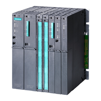
Page 13: Product Overview
www.gkbpx.com Product Overview Overview of the S7-400 The S7-400 is a programmable controller. Almost any automation task can be implemented with a suitable choice of S7-400 components. S7-400 modules have a block design for swing-mounting in a rack. Expansion racks are available to extend the system. In this chapter, we show you the most important components with which you can assemble an S7-400. - Page 14 www.gkbpx.com Product Overview Overview of the M7-400 The SIMATIC S7 programmable controller is extended by the SIMATIC M7 automation computer with its AT-compatible computer functionality. This enables the SIMATIC user to make use of the open software world, either as an extension to an S7 programmable controller or as a stand-alone M7 computer system.
- Page 15 www.gkbpx.com Product Overview Components of an S7-400 The most important components of the S7-400 and their functions are given in the following tables: Components Function Illustration Racks ... provide the mechanical and (UR: Universal Rack) electrical connections between (CR: Central Rack) the S7-400 modules.
- Page 16 www.gkbpx.com Product Overview Components Function Illustration PG cables ...connect a CPU to a programming device. PROFIBUS components ... connect the S7-400 to other for example, PROFIBUS bus S7-400 devices or programming terminal devices. RS 485 repeaters ...amplify data signals on bus lines and links bus segments.
- Page 17 www.gkbpx.com Product Overview Components Function Illustration Expansion Modules (EXMs) ... serve to accommodate three interface submodules (IFs). AT Adapter Modules (ATMs) ... provide a slot for a 16-bit AT module (up to 164 mm long). Mass Storage Modules (MSMs) ... serve to store programs and data on a hard disk (2.5”) or floppy disk (3.5”).
- Page 18 Location of Order Number and Product Version The order number and product version are printed on every module of the SIMATIC S7-400/M7-400. The following figure shows their locations on a module. For the product version, an X is entered instead of the valid number. The following figure shows a module with Product Version 1.
- Page 19 www.gkbpx.com Product Overview Example of a Rating Plate SIMATIC M7 X 2 3 4 Order no. Product version Approvals and marks Module designation S7-400 and M7-400 Programmable Controllers, Installation Manual C79000-G7076-C424-01...
- Page 20 www.gkbpx.com Product Overview S7-400 and M7-400 Programmable Controllers, Installation Manual C79000-G7076-C424-01...
-
Page 21: Installing The S7-400
www.gkbpx.com Installing the S7-400 Chapter Overview Section Description Page Assembling an S7-400 Assembling the Central Rack (CR) and Expansion Rack (ER) Segmented CR Mounting and Grounding the Racks Chassis Ground Connection in the Non-Isolated Configuration 2-14 Methods of Ventilation 2-16 Changing the Ventilation with the Cable Duct and Fan 2-18 Subassembly... -
Page 22: Assembling An S7-400
www.gkbpx.com Installing the S7-400 Assembling an S7-400 Introduction An S7-400 programmable controller consists of a central rack (CR) and one or more expansion racks (ERs), as required. You use ERs when there are insufficient slots in the CR for your application, or when you wish to operate signal modules separated from the CR (e.g. - Page 23 www.gkbpx.com Installing the S7-400 Connecting the CR and ER(s) To connect one or more ERs to a CR, you must fit one or more send IMs in the The send IMs have two interfaces. You can connect one chain of up to four ERs to each of the two interfaces of a send IM in the CR.
- Page 24 www.gkbpx.com Installing the S7-400 Ways of Connecting Central and Expansion Racks IM 460-3 IM 460-1 IM 460-0 Central rack CR Expansion without 5 V transfer, local Expansion rack ER 1 Expansion rack ER 4 IM 461-0 IM 461-0 Chain length 3 m max. Expansion with 5 V transfer, local Expansion rack ER 1 IM 461-1...
- Page 25 www.gkbpx.com Installing the S7-400 Rules for Connection When you connect a central rack to expansion racks, you must observe the following rules: You can connect up to 21 ERs of the S7-400 to one CR. The ERs are assigned numbers to identify them. The rack number must be set on the coding switch of the receive IM.
-
Page 26: Assembling The Central Rack (Cr) And Expansion Rack (Er)
www.gkbpx.com Installing the S7-400 Assembling the Central Rack (CR) and Expansion Rack (ER) Function of the racks The racks of the S7-400 system form the basic framework which accepts the individual modules. The modules exchange data and signals and are powered via the backplane bus. - Page 27 www.gkbpx.com Installing the S7-400 Electrical Supply The modules inserted in the rack are supplied with the required operating voltages (5 V for logic, 24 V for interfaces) via the backplane bus and base connector, by the power supply module fitted in the slot on the extreme left in the rack. For local connections, ERs can also be supplied with power via the IM 460-1 / IM 461-1 interface modules.
-
Page 28: Segmented Cr
www.gkbpx.com Installing the S7-400 Segmented CR Properties The “segmented” characteristic relates to the configuration of the CR. In the (non-segmented) CR the I/O bus is continuous and interconnects all 18 or 9 slots; in the segmented CR, however, the I/O bus consists of two I/O bus segments. A segmented CR has the following important characteristics: The communication bus is continuous (global), whilst the I/O bus is divided into two I/O bus segments of 10 and 8 slots respectively. -
Page 29: Mounting And Grounding The Racks
www.gkbpx.com Installing the S7-400 Mounting and Grounding the Racks Important Notes on Installation The S7-400 racks are designed for wall mounting, mounting on rails, and for installation in frames and cabinets. Their mounting dimensions comply with DIN 41 494. According to the UL/CSA and the EU Directive 73/23/EEC (low-voltage directive), installation in a cabinet, a casing, or a closed operations room is necessary in order to fulfil the requirements for electrical safety (see Reference Manual , Chapter 1). - Page 30 www.gkbpx.com Installing the S7-400 Space Required When Using Cable Channels and Fan Subassemblies A cable duct or fan subassembly must be installed in the 19-inch pitch immediately below the rack. Additional space for cable routing must be provided on both sides. The following figure shows how much space you need to allow for when using a cable duct or fan subassembly.
- Page 31 www.gkbpx.com Installing the S7-400 Step 2: Mounting the Rack Screw the rack to the base. Is the base material a grounded metal plate or a grounded equipment plate? If so: Establish a low-impedance connection between rack and base material. With painted and anodized metals, for example, use a suitable contact agent or special contact washers.
- Page 32 www.gkbpx.com Installing the S7-400 M6 threaded bolt Contact washer Terminal Plain washer M6 nut To chassis ground Step 4: Mounting Additional Racks If you assemble an S7-400 with two or more racks, you must allow additional clearance between the individual racks or install a fan subassembly or cable duct. The figure below shows the clearance you must allow between two racks of the S7-400 during installation.
- Page 33 www.gkbpx.com Installing the S7-400 The figure below shows how much space you must allow for when assembling an S7-400 from two racks with a cable duct or fan subassembly. This requirement is increased by a height of 400 mm for each additional rack with a cable duct or fan subassembly.
-
Page 34: Chassis Terminal Connection In The Non-Isolated Configuration
www.gkbpx.com Installing the S7-400 Chassis Terminal Connection in the Non-Isolated Configuration Reference Point The racks offer the option of connecting the 24-V load voltage ground in the non-isolated configuration to the 5-V ground (reference potential M, logic ground). Connect the chassis ground to the reference point for non-isolated modules. The reference point is metallically connected to the reference potential M. - Page 35 www.gkbpx.com Installing the S7-400 The following figure shows the chassis ground connection to the reference point. Threaded hole Terminal Spring washer M4 screw S7-400 and M7-400 Programmable Controllers, Installation Manual 2-15 C79000-G7076-C424-01...
-
Page 36: Methods Of Ventilation
www.gkbpx.com Installing the S7-400 Methods of Ventilation Methods of Ventilation Under extreme ambient conditions, particularly when operating the S7-400 modules in cabinets, you can use the cable duct or fan subassembly to optimize ventilation. There are two methods of supplying air to the modules. You draw in air either from the back or from below. - Page 37 www.gkbpx.com Installing the S7-400 The following figure shows the ventilation when air is drawn in from the bottom. Exhaust air Wall Ç Ç Ç Ç Ç Ç Modules Ç Ç Cable duct or fan Ç subassembly Ç Ç Ç Ç Ç...
-
Page 38: Changing The Ventilation With The Cable Duct And Fan Subassembly
www.gkbpx.com Installing the S7-400 Changing the Ventilation with the Cable Duct and Fan Subassembly Changing the Ventilation At the base of the cable duct and the fan subassembly, there is a cover that you can move in order to change the air duct. To do this, proceed as follows: 1. - Page 39 www.gkbpx.com Installing the S7-400 Cover Delivered state: Cover fitted at bottom (supply air from the rear) Base Quick-release locks Snap catches Cover Cover fitted at back (supply air from below) Base Snap hinges State When Shipped The cover is fitted in the base of the cable duct or fan subassembly. Air is supplied from the back.
-
Page 40: Installing The Fan Subassembly
www.gkbpx.com Installing the S7-400 Installing the Fan Subassembly Procedure 1. Remove the left cover from the fan subassembly. Using a 17 mm open-ended wrench, slacken the quick-release lock a quarter turn. Pull out the left cover of the fan subassembly. To do this, move the left cover parallel to the fan subassembly in order to avoid damaging the plug-in contact on the other side. - Page 41 www.gkbpx.com Installing the S7-400 4. Attach the dummy plates to the free slots: – Place the dummy plates on the rear wall of the cable routing, – Push the dummy plates back so that the noses of the dummy plates will fit into the cutouts provided, –...
-
Page 42: Installing The Cable Duct
www.gkbpx.com Installing the S7-400 Installing the Cable Duct Procedure 1. Install the cable duct in the 19-inch pitch directly under the rack or between two racks. Use M6 size screws for mounting. The following figure shows how to mount the cable duct between two racks. 19-inch reference level S7-400 and M7-400 Programmable Controllers, Installation Manual 2-22... -
Page 43: Choosing And Setting Up Cabinets With The S7-400
www.gkbpx.com Installing the S7-400 2.10 Choosing and Setting up Cabinets with the S7-400 Why Cabinets are Required With larger installations and in an environment subject to interference or pollution, you can install the S7-400 in cabinets. The requirements of UL/CSA are met, for example, by an installation in cabinets. - Page 44 www.gkbpx.com Installing the S7-400 Table 2-1 provides an overview of the most common types of cabinet. You will also find the principle of heat removal, as well as the estimated, maximum achievable power loss removal and the degree of protection. Table 2-1 Types of Cabinet Open Cabinets...
- Page 45 600 x 600 x 2000 mm as a function of power dissipation. These values only apply if you observe the specified installation dimensions and clearances for racks. Further information can be found in Siemens catalogs NV21 and ET1.
- Page 46 www.gkbpx.com Installing the S7-400 Example for Determining the Type of Cabinet The following example clarifies the maximum ambient temperature which is permissible for a particular power dissipation with various types of cabinet. The following equipment configuration is to be installed in a cabinet: 1 central rack 150 W 2 expansion racks of 150 W power dissipation each...
-
Page 47: Rules For The Arrangement Of Modules
www.gkbpx.com Installing the S7-400 2.11 Rules for the Arrangement of Modules Rules for S7-400 and M7-400 Given in this section are the rules you must observe when arranging modules in the S7-400. The rules for M7-400 modules can be found in Section 8.1 “Mechanical Configuration”. -
Page 48: Installing Modules In A Rack
www.gkbpx.com Installing the S7-400 2.12 Installing Modules in a Rack Introduction All modules are installed in a rack using the same procedure. Caution Modules and racks can be damaged. If you use force when installing modules in a rack, these components may be damaged. - Page 49 www.gkbpx.com Installing the S7-400 Removing the Cover With modules which have a cover (for example, power supply modules and CPUs), you remove this before installing the module in the rack. Proceed as follows: 1. Press the locking lever down (1). 2.
- Page 50 www.gkbpx.com Installing the S7-400 Attaching the Modules Attach the modules one by one (1) and swing them carefully downwards (2). If you feel a resistance when swinging the module down, raise it slightly and then continue. Figure 2-4 Attaching the Modules Screwing the Modules in Place Tightening torque 0.8 to 1.1 Nm...
- Page 51 www.gkbpx.com Installing the S7-400 Inserting the Keyswitch You can insert the key in the CPU in the STOP position of the switch. You can remove the key in the STOP or RUN settings. Figure 2-6 Inserting the Key in the CPU S7-400 and M7-400 Programmable Controllers, Installation Manual 2-31 C79000-G7076-C424-01...
-
Page 52: Marking The Modules With Slot Labels
www.gkbpx.com Installing the S7-400 2.13 Marking the Modules with Slot Labels Slot Number Once the modules are installed, you should mark each one with its slot number to avoid the risk of mixing up modules during operation. If modules do get mixed up, you may have to reconfigure the assembly. -
Page 53: Methods Of Expansion And Networking
www.gkbpx.com Installing the S7-400 2.14 Methods of Expansion and Networking Introduction Apart from the structures mentioned in this chapter, other expansions are possible, for example, by connecting distributed I/Os or by networking. The modules with which you can connect an M7-400 to PROFIBUS DP can be found in Section 8.7.6 “Starting Up a PROFIBUS-DP Subnet.”... -
Page 54: Accessories
www.gkbpx.com Installing the S7-400 2.15 Accessories Accessories Some of the accessories needed for fitting the modules in the rack are provided in the packaging of the modules and racks. The front connectors of the signal modules must always be ordered separately. There are also optional accessories for some modules. -
Page 55: Addressing The S7-400
www.gkbpx.com Addressing the S7-400 Chapter Overview Section Description Page Geographical and Logical Addresses How to Determine the Default Address of a Module How to Determine the Default Address of a Channel S7-400 and M7-400 Programmable Controllers, Installation Manual C79000-G7076-C424-01... -
Page 56: Geographical And Logical Addresses
www.gkbpx.com Addressing the S7-400 Geographical and Logical Addresses Addresses In order to control a process, you must address the channels (inputs and outputs) of the signal modules from the user program. You must establish a unique assignment between the (geographical) location of a channel and an address in the user program. - Page 57 www.gkbpx.com Addressing the S7-400 Default Addressing Under certain conditions, the CPU can handle the assignment between logical address and geographical address for you (default addressing). The logical addresses are then permanently assigned to the slots (default address). Distributed I/Os are not taken into account. Conditions for Default Addressing The CPU assigns default addresses under the following conditions: If only signal modules are inserted...
-
Page 58: How To Determine The Default Address Of A Module
www.gkbpx.com Addressing the S7-400 How to Determine the Default Address of a Module Default Addressing You determine the default address of a module from the number of the slot of the module in the CR. The algorithms used to calculate the default address are different for analog and digital modules. - Page 59 www.gkbpx.com Addressing the S7-400 Default Addresses of Analog Modules On the S7-400, the default addresses for analog modules start from 512 (first slot in the central rack which is usually occupied by the power supply module) up to 1600. The algorithm used to calculate the default address of an analog module is: Default address = (slot number - 1) x 64 + 512 Example The default address of an analog module in the 6th slot is as follows:...
-
Page 60: How To Determine The Default Address Of A Channel
www.gkbpx.com Addressing the S7-400 How to Determine the Default Address of a Channel Channel on a Digital Module A channel on a digital module is addressed bit-wise. For a digital input module with 32 inputs, four bytes (starting with the default address of the module) are used to address the inputs, and for a digital input module with 16 inputs, two bytes are used. - Page 61 www.gkbpx.com Addressing the S7-400 Channel on an Analog Module Channels on analog modules are addressed word-wise. Starting with the default address of the module, which also represents the address of the uppermost channel of the module, the addresses of the individual channels (from top to bottom) increase by two bytes (= one word).
- Page 62 www.gkbpx.com Addressing the S7-400 S7-400 and M7-400 Programmable Controllers, Installation Manual C79000-G7076-C424-01...
-
Page 63: Wiring The S7-400
www.gkbpx.com Wiring the S7-400 Chapter Overview Section Description Page General Rules and Regulations for Operating the S7-400 Supplying Power to Modules Choosing the Power Supply Module Choosing the Load Current Power Supply Assembling an S7-400 with Process I/Os Assembling an S7-400 with Grounded Reference Potential M 4-10 Assembling an S7-400 with Ungrounded Reference Potential 4-11... -
Page 64: General Rules And Regulations For Operating The S7-400
www.gkbpx.com Wiring the S7-400 General Rules and Regulations for Operating the S7-400 General Basic Rules On account of the many possible applications of the S7-400, this chapter can only cover the basic rules for the electrical configuration. You must at least comply with these basic rules to ensure fault-free operation of the S7-400. - Page 65 www.gkbpx.com Wiring the S7-400 With ..you must ensure ... stationary equipment and that a supply disconnector (switch) is installed in the systems without all-pole building. disconnector load power supplies and that the set line voltage range corresponds to the local line power supply modules voltage.
- Page 66 www.gkbpx.com Wiring the S7-400 Protection Against Other Electrical Effects The following table shows the other external effects against which you must provide protection. Protection against ..by means of ... inadvertent actuation of a suitable arrangement or covering of keyboard and operator controls operator controls or a recessed arrangement of operator controls.
-
Page 67: Supplying Power To Modules
www.gkbpx.com Wiring the S7-400 Supplying Power to Modules Power Supply Modules and Load Current Power Supplies The modules of the S7-400 system are supplied with all the required operating voltages by a power supply module, via the backplane bus of the rack. Which power supply module you use in a rack depends on your system requirements (line voltage, current consumption of the modules used). -
Page 68: Choosing The Power Supply Module
www.gkbpx.com Wiring the S7-400 Choosing the Power Supply Module Estimating the Power Requirement You should make an estimate of the power requirement for each rack of your S7-400 system in order to select the appropriate power supply module for the rack. Selection of the power supply for an M7-400 configuration is described separately in Section 8.3 “Electrical Configuration.”... -
Page 69: Choosing The Load Current Power Supply
Required for ... Remarks the Load Current Power Supply Safe isolation Modules which must be The Siemens SITOP power load current supplied with voltages supplies have this characteristic. 60 VDC or 25 VAC. 24 VDC load circuits Tolerances of the... -
Page 70: Assembling An S7-400 With Process I/Os
www.gkbpx.com Wiring the S7-400 Assembling an S7-400 with Process I/Os Definition of a Grounded Supply (TN-S Network) In grounded supplies, the neutral conductor of the system is grounded. A single fault between a live conductor and ground or a grounded part of the installation results in tripping of the protective devices. - Page 71 www.gkbpx.com Wiring the S7-400 S7-400 in the Overall Installation Shown in Figure 4-1 is the position of the S7-400 in the overall installation (load current power supply and grounding concept) with supply from a TN-S system. Note: The arrangement of supply terminals shown is not the actual arrangement; it has been chosen for reasons of clarity.
-
Page 72: Assembling An S7-400 With Grounded Reference Potential (0 V)
www.gkbpx.com Wiring the S7-400 Assembling an S7-400 with Grounded Reference Potential (0 V) Application You use an S7-400 with grounded reference potential in machines or industrial plants. Discharge of Interference Currents When the S7-400 is configured with a grounded reference potential, any interference currents are discharged to the chassis ground. -
Page 73: Assembling An S7-400 With Ungrounded Reference Potential
www.gkbpx.com Wiring the S7-400 Assembling an S7-400 with Ungrounded Reference Potential (Ungrounded Configuration) Application In large installations, it may be necessary to configure the S7-400 with an ungrounded reference potential, for example, for ground fault monitoring. This is the case in the chemical industry or in power plants, for example. Discharge of Interference Currents With the S7-400 in an ungrounded configuration, any interference currents are discharged to the chassis ground via an RC network integrated in the rack. - Page 74 Filtering the 24 VDC Supply When you power the S7-400 from a battery with the ungrounded configuration, you must provide interference suppression for the 24 VDC supply. Use a Siemens power cable filter, such as the B84102-K40. Insulation Monitoring If a double fault could cause a hazardous state in the installation, you must provide insulation monitoring.
-
Page 75: Assembling An S7-400 With Isolated Modules
www.gkbpx.com Wiring the S7-400 Assembling an S7-400 with Isolated Modules Definition In a configuration with isolated modules, the reference potentials of the control circuit (0 V ) and the load circuit 0 V ) are isolated (see also Figure 4-4). internal external Application... - Page 76 www.gkbpx.com Wiring the S7-400 Configuration with Isolated Modules Shown in Figure 4-4 are the potentials of an S7-400 configured with isolated input and output modules. Racks internal Data Reference potential M Ground bus in cabinet external 230 VAC load current PS 24 VDC load current PS Figure 4-4 Simplified Representation of Configuration with Isolated Modules...
-
Page 77: Shielding Cables
www.gkbpx.com Wiring the S7-400 Shielding Cables Purpose of the Shielding A cable is shielded to attenuate the effects of magnetic, electrical, and electromagnetic interference on this cable. Principle of Operation Interference currents on cable shields are discharged to ground via the shield bus which is electrically connected to the housing. - Page 78 www.gkbpx.com Wiring the S7-400 Note In the event of potential differences between grounding points, a circulating current may flow via the shield connected at both ends. In this case, install an additional equipotential bonding conductor (see Section 4.10). Observe the following points with regard to the shield: Only use cable clamps made of metal to secure braided shields.
-
Page 79: Equipotential Bonding
www.gkbpx.com Wiring the S7-400 4.10 Equipotential Bonding Potential Differences Potential differences can occur between separate system components, leading to high transient currents; for example, if cable shields are fitted on both sides and grounded at different system components. Potential differences can be caused by different electrical supplies. Equipotential Bonding Conductor You must reduce the potential differences by laying equipotential bonding conductors to ensure that the electronic components used function correctly. - Page 80 www.gkbpx.com Wiring the S7-400 Figure 4-5 Routing Equipotential Bonding Conductor and Signal Line S7-400 and M7-400 Programmable Controllers, Installation Manual 4-18 C79000-G7076-C424-01...
-
Page 81: Protection Against Inductive Surge Voltages
www.gkbpx.com Wiring the S7-400 4.11 Protection Against Inductive Surge Voltages Integrated Overvoltage Protection The digital output modules on the S7-400 have an integrated overvoltage protection facility. Surge voltages are produced when inductors such as relay coils and contactors are switched off. Additional Surge Suppression Inductors should only have additional surge suppression devices in the following cases:... - Page 82 www.gkbpx.com Wiring the S7-400 Suppression for DC-Operated Coils DC-operated coils are interconnected to diodes or zener diodes. With diode With zener diode Figure 4-7 Suppression for DC-Operated Coils Suppression with Diodes / Zener Diodes Suppression with diodes or zener diodes exhibits the following characteristics: Switching overvoltages can be avoided entirely.
-
Page 83: Grounding
www.gkbpx.com Wiring the S7-400 4.12 Grounding Introduction Grounding in accordance with regulations and conscientiously implemented is the prerequisite for proper functioning of a programmable controller. Each individual component of the S7-400 and of the controlled system must be properly grounded. Ground Connections Low-resistance ground connections reduce the risk of electric shock in the event of a short-circuit or faults in the system. - Page 84 www.gkbpx.com Wiring the S7-400 Connecting the Load Voltage Ground Many output modules require an additional load voltage to switch the actuators. Two different modes are possible for this load voltage: Non-isolated operation Floating operation The following table shows how the load voltage ground is connected in the individual modes.
-
Page 85: Interference-Free Configuration For Local And Remote Connections
www.gkbpx.com Wiring the S7-400 4.13 Interference-Free Configuration for Local and Remote Connections Use only Approved Components Note If you use components which are not approved for setting up local and remote connections, interference rejection may be impaired. Interference-Free Configuration for Local Connections If you connect the CR and ER via suitable interface modules (send IM and receive IM), no particular shielding and grounding need be implemented. - Page 86 www.gkbpx.com Wiring the S7-400 Send IM Receive IM Shield/protective ground bar Î Î Î Î Î Î Î Î Î < 7 V Figure 4-9 Shielding and Grounding the Connecting Cable for a Remote Connection Special Cases For remote connections, you must use precut/preassembled connecting cables of fixed length.
-
Page 87: Wiring Rules
www.gkbpx.com Wiring the S7-400 4.14 Wiring Rules Lines and Tools For wiring the S7-400 modules, there are some rules for the cables and for the tool you use. Information on connecting an M7-400 module assembly can be found in Section 8.5. Rules for ... - Page 88 www.gkbpx.com Wiring the S7-400 Rules for ... Power Supply ... Front Connectors Blade width and 3.5 mm (cylindrical 3.5 mm (cylindrical 0.5 mm x 3.5 mm shape of the screw shape) shape) DIN 5264 driver Tightening torque: 0.6 to 0.8 Nm 0.6 to 0.8 Nm for connecting conductors...
-
Page 89: Setting The Vac Power Supply Module To The Line Voltage
www.gkbpx.com Wiring the S7-400 4.15 Setting the VAC Power Supply Module to the Line Voltage Setting the Voltage Selector Switch An S7-400 with VAC power supply can be operated from either a 120 V or 230 V line voltage. Check whether the voltage selector switch is set to your line voltage. To set the VAC power supply module to the correct line voltage, follow the steps outlined below: 1. -
Page 90: Wiring The Power Supply Module
www.gkbpx.com Wiring the S7-400 4.16 Wiring the Power Supply Module Power Supply Connector You use the power supply connector to connect a power supply module to your supply. When delivered, the power supply connector is plugged into the power supply module. There are two versions (AC and DC) of power supply connector. The two versions are coded, meaning an AC connector can only be plugged into an AC power supply module, and a DC connector can only be plugged into a DC power supply module. - Page 91 www.gkbpx.com Wiring the S7-400 Wiring the Power Supply Connector To wire the power supply connector, follow the steps outlined below: Warning There is a risk of personal injury. If you wire the connector with voltage applied, you may suffer a shock and personal injury.
- Page 92 www.gkbpx.com Wiring the S7-400 6. Slacken the screw of the strain relief and insert the cable. 7. Connect the cores according to the illustration on the cover of the power supply connector. Connect the longer core to PE. Screw on the cores with a torque of 0.6 to 0.8 Nm.
- Page 93 www.gkbpx.com Wiring the S7-400 Plugging In the Power Supply Connector You can only plug in the connector when the power supply module is installed (lower mounting screw tightened). Caution An AC power supply module can be damaged. If you set the voltage selector switch of an AC power supply module to 120 V and connect the power supply module to a 230 V supply, a fault may develop on the power supply module.
-
Page 94: Wiring The Signal Modules
www.gkbpx.com Wiring the S7-400 4.17 Wiring the Signal Modules Procedure There are two steps for providing the connection between the signal modules of your S7-400 and the sensors and actuators of your plant: 1. Wiring the front connector. This serves to connect the cables to and from the sensors/actuators to the front connector. - Page 95 www.gkbpx.com Wiring the S7-400 Levering the cover off Opening the cover Pulling the cover off 4. Cut the wires to the right lengths so that no loops are created in the front connector after wiring. 5. Isolate the wires according to the table in Section 4.14. Note The front connectors contain a jumper needed for functioning of some signal modules.
-
Page 96: Wiring The Front Connector, Crimp Snap-On Terminals
www.gkbpx.com Wiring the S7-400 4.18 Wiring the Front Connector, Crimp Snap-On Terminals Procedure To wire the prepared front connector, follow the steps outlined below: 1. Strip the conductors over approx. 5 mm. 2. Crimp the contacts onto the conductors. You can use a crimping tool which can be ordered as an accessory for your signal modules. -
Page 97: Wiring The Front Connector, Screw-Type Terminals
www.gkbpx.com Wiring the S7-400 4.19 Wiring the Front Connector, Screw-Type Terminals Procedure To wire the prepared front connector, follow the steps outlined below: 1. Are you using wire end ferrules? If so: Strip the conductors over 10 mm. Press-fit the wire end ferrules onto the conductors. -
Page 98: Wiring The Front Connector, Spring-Type Terminals
www.gkbpx.com Wiring the S7-400 4.20 Wiring the Front Connector, Spring-Type Terminals Procedure To wire the prepared front connector, follow the steps outlined below: 1. Are you using wire end ferrules? If so: Strip the conductors over 10 mm. Press-fit the wire end ferrules onto the conductors. - Page 99 www.gkbpx.com Wiring the S7-400 Principle of the Spring Contact The following figure shows the principle of spring contacts. Releasing and engaging from the front is illustrated. 1. Insert the screwdriver 2. Insert the wire into the spring contact as far as it will go 3.
-
Page 100: Fitting The Strain Relief
www.gkbpx.com Wiring the S7-400 4.21 Fitting the Strain Relief Cable Ties as Strain Relief When you have wired the front connector, the cable tie provided should be fitted at the bottom of the front connector as a strain relief for the connected cable. There are three ways of fitting the strain relief, according to the thickness of the cable. -
Page 101: Labeling A Front Connector
www.gkbpx.com Wiring the S7-400 4.22 Labeling a Front Connector Labels and Terminal Diagram Each signal module is provided with three labels: two blank labels and one printed label showing the terminal diagram for inputs and outputs. Templates for creating additional labels can be found in the Appendix of the Reference Manual . - Page 102 www.gkbpx.com Wiring the S7-400 To label a front connector, follow the steps outlined below: 1. Enter the addresses of the individual channels on the two labels. Note the slot numbers on the labels to record the assignment of front connector to module. 2.
-
Page 103: Fitting The Front Connector
www.gkbpx.com Wiring the S7-400 4.23 Fitting the Front Connector Principle of a Coding Key To reduce the risk of a wired front connector being plugged into the wrong type of module after rewiring or module replacement, the signal modules have a coding key for front connectors. - Page 104 www.gkbpx.com Wiring the S7-400 To plug in the front connector, follow the steps outlined below: 1. Hold the front connector horizontally and engage the front connector with the coding key. After an audible click, the front connector will engage with the mount and can be swung upwards.
- Page 105 www.gkbpx.com Wiring the S7-400 Figure 4-17 shows how to screw on the front connector. Figure 4-17 Screwing On the Front Connector S7-400 and M7-400 Programmable Controllers, Installation Manual 4-43 C79000-G7076-C424-01...
-
Page 106: Interconnecting The Cr And Er(S)
www.gkbpx.com Wiring the S7-400 4.24 Interconnecting the CR and ER(s) Interconnecting the Interface Modules When you assemble a programmable controller comprising a CR and one or more ERs, you connect the racks via the connecting cables of the interface modules. To interconnect the interface modules, follow the steps outlined below: 1. - Page 107 www.gkbpx.com Wiring the S7-400 9. Connect the remaining receive IMs by connecting one send interface (lower female connector X2) to one receive interface (upper male connector X1) in each case. Send IM Receive IM Receive IM Terminator Figure 4-19 Connection Between a Send IM and Two Receive IMs 10.Plug the terminator into the lower female connector of the receive IM in the last ER of the chain (see Reference Manual , Chapter 7).
-
Page 108: Setting The Fan Subassembly To The Line Voltage And Wiring It
www.gkbpx.com Wiring the S7-400 4.25 Setting the Fan Subassembly to the Line Voltage and Wiring It Setting the Fan Subassembly to the Line Voltage Check whether the voltage selector switch in the fan subassembly is set to your line voltage (see Figure 4-20). Fuse The fan subassembly has two standard fuses: A 250 mA slow blow fuse for the 120 V range... -
Page 109: Routing Cables Using Cable Ducts Or Fan Subassemblies
www.gkbpx.com Wiring the S7-400 4.26 Routing Cables Using Cable Ducts or Fan Subassemblies Cable Routing Depending on the number of cables and plug-in lines merging at the particular rack, the cross-section of the cable duct or fan subassembly may not be sufficient to accept all cables. -
Page 110: Routing Cables Using Fiber-Optic Cables
www.gkbpx.com Wiring the S7-400 4.27 Routing Cables Using Fiber-Optic Cables Cable Routing Indoor fiber-optic cables (for example, for connecting synchronization submodules) are permitted for use in buildings, cable ducts, and channel trunking. The maximum strain load when assembling is 1000 N and during operation 150 N. Bending Radius When laying cables, you should maintain the following minimum bending radii: Next to connector: 55 mm... -
Page 111: Networking
www.gkbpx.com Networking Chapter Overview Section Description Page Configuring a Network Fundamentals Rules for Configuring a Network Cable Lengths 5-15 PROFIBUS-DP Bus Cables 5-18 Bus Connectors 5-19 RS 485 Repeater 5-23 PROFIBUS-DP network with fiber-optic cables 5-25 S7-400 and M7-400 Programmable Controllers, Installation Manual C79000-G7076-C424-01... -
Page 112: Configuring A Network
www.gkbpx.com Networking Configuring a Network Subnets You can connect an S7-400 device to various subnets: Via a Simatic Net CP Ethernet to an Industrial Ethernet subnet Via a Simatic Net CP PROFIBUS to a PROFIBUS-DP subnet Via the integrated multipoint interface to an MPI subnet Via the integrated PROFIBUS-DP interface to a PROFIBUS-DP subnet With the M7-400, an MPI or PROFIBUS-DP network can be configured in the same way. -
Page 113: Fundamentals
www.gkbpx.com Networking Fundamentals Station = Node Declaration: All the stations you connect in a network are referred to as nodes in the following. Segment A segment is a bus cable between two terminating resistors. A segment can contain up to 32 nodes. Furthermore, a segment is limited by the permissible cable length according to the transmission rate. - Page 114 www.gkbpx.com Networking Number of Nodes PROFIBUS DP 127 * (default: 32) of which: 1 master (reserved) 1 PG port (reserved) 1 PG port (reserved) 125 slaves or other masters Observe the CPU-related maximum numbers in the Reference Manual , Chapter 4 MPI/PROFIBUS-DP Addresses In order for all nodes to be able to communicate with one another, you must assign them an address:...
- Page 115 www.gkbpx.com Networking Communication from PG/OP to Module without MPI If one of the programming devices or operator panels connected to a multipoint interface (MPI) communicates with an S7-400 module which does not have an MPI connection (for example, SINEC CPs, FM 456 etc.), this module can be reached via the CPU to whose MPI the programming device or operator panel is connected.
- Page 116 www.gkbpx.com Networking PG Access A CPU exchanges data with other systems using communication mechanisms, for example with other programmable controllers, with operator interface stations (OP, OS) or with programming devices (see Figure 5-2). SIMATIC NET DP network Slave Figure 5-2 Data Exchange Process communication, including communication services for data exchange between programmable controllers (PLC –...
-
Page 117: Rules For Configuring A Network
www.gkbpx.com Networking Rules for Configuring a Network Rules Observe the following rules for connecting the nodes of a network: Before you interconnect the individual nodes of the network, you must assign to each node the MPI address and the highest MPI address or PROFIBUS-DP address. - Page 118 www.gkbpx.com Networking Data Packets in the MPI Network Observe the following feature in the MPI network: Note If you connect an additional CPU to the MPI network during operation, data may be lost. Remedy: 1. Disconnect power from the nodes to be connected. 2.
- Page 119 Terminating Resistor on the RS 485 Repeater L+ M PE M 5.2 A1 B1 A1 B1 Terminating resistor for bus segment 1 Terminating resistor for bus segment 2 SIEMENS RS 485 REPEATER A2 B2A2 B2 S7-400 and M7-400 Programmable Controllers, Installation Manual C79000-G7076-C424-01...
- Page 120 www.gkbpx.com Networking Example: Terminating Resistor in the MPI Network The figure below shows where you have to connect the terminating resistor in a possible configuration for an MPI network. S7-400 Programming device S7-400 S7-400 S7-300 RS 485 repeater Spur line Programming device Terminating resistor switched on S7-400 and M7-400 Programmable Controllers, Installation Manual...
- Page 121 www.gkbpx.com Networking Example of an MPI Network Programming S7-400** S7-400 S7-400 S7-400 device OP** S7-400 S7-400 S7-300 Programming device* * Only connected via spur line for startup/maintenance (with default MPI address) ** Connected to the MPI network later on (with default MPI address) 0 to x MPI addresses of nodes Terminating resistor switched on S7-400 and M7-400 Programmable Controllers, Installation Manual...
- Page 122 www.gkbpx.com Networking Example of a PROFIBUS-DP Network S7-400 with CPU 414-2-DP as DP Master ET 200M Programming ET 200M S5-95U device ET 200B ET 200B Programming device* * Only connected via spur line for startup/maintenance (with default PROFIBUS-DP address = 0) 0 to x PROFIBUS-DP addresses of nodes Terminating resistor switched on S7-400 and M7-400 Programmable Controllers, Installation Manual...
- Page 123 www.gkbpx.com Networking Example Using a CPU 414-2 The figure below shows an example of a configuration with CPU 414-2 DP which is integrated in an MPI network and simultaneously used as DP master in a PROFIBUS-DP network. In both networks, the node numbers can be assigned separately without conflicts resulting.
- Page 124 www.gkbpx.com Networking Programming Device Access Beyond Network Limits (Routing) You can access all modules beyond network limits using a programming device. Programming device / PC 3 S7-400 with S7-400 with CPU 417 CPU 416 MPI network 3 MPI network 1 S7-300 with CPU 318 S7-300 with...
-
Page 125: Cable Lengths
www.gkbpx.com Networking Cable Lengths Segment in the MPI Network In a segment of an MPI network, you can use cable lengths of up to 50 m. This 50 m applies from the first node to the last node in the segment. Table 5-1 Permitted Cable Length of a Segment in an MPI Network Transmission Rate... - Page 126 www.gkbpx.com Networking Lengths of Spur Lines If you do not fit the bus cable directly at the bus connector (for example, when using a PROFIBUS-DP bus terminal), you must take into account the maximum possible spur line length. The following table gives the maximum lengths of spur lines allowed per bus segment: Upward of 3 Mbps use PG connecting cable, order no.
- Page 127 www.gkbpx.com Networking Example The figure below shows a possible configuration of an MPI network. This example clarifies the maximum possible distances in an MPI network. Programming S7-400 S7-400 S7-400 device* RS 485 repeater max. Spur line 1000 m Programming device* max.
-
Page 128: Profibus-Dp Bus Cables
Networking PROFIBUS-DP Bus Cables PROFIBUS-DP Bus Cables Siemens supply the following PROFIBUS-DP bus cables (see catalog ST 70): PROFIBUS-DP bus cable 6XV1 830-0AH10 PROFIBUS-DP cable for burying in ground 6XV1 830-3AH10 PROFIBUS-DP trailing cable 6XV1 830-3BH10 PROFIBUS-DP bus cable with PE sheath (for foodstuffs and... -
Page 129: Bus Connectors
www.gkbpx.com Networking Bus Connectors Purpose of the Bus Connector The bus connector is used to connect the PROFIBUS-DP bus cable to the MPI or PROFIBUS-DP interface. In this way, you establish the connection to other nodes. There are two different bus connectors: Bus connector without PG connector (6ES7 972-0BA20-0XA0) Bus connector with PG connector... - Page 130 www.gkbpx.com Networking Connecting Bus Cables to Bus Connectors ( 6ES7 972-0B.20 ...) 1. Strip the bus cable according to the following figure. Angled outgoing cable unit Without PG connector With PG connector 2. Open the housing of the bus connector by slackening the housing screw and swinging the cover upwards.
- Page 131 www.gkbpx.com Networking Bus cable connection for first Bus cable connection for all and last station on the bus other stations on the bus A B A B A B A B The bus cable can be Ç Ç connected either right or left.
- Page 132 www.gkbpx.com Networking Removing the Bus Connector With a looped-through bus cable you can remove the bus connector from the PROFIBUS-DP interface at any time, without interrupting data traffic on the bus. Warning Interference to the data traffic on the bus is possible. A bus segment must always be terminated with the terminating resistor at both ends.
-
Page 133: Rs 485 Repeater
www.gkbpx.com Networking RS 485 Repeater Purpose of the RS 485 Repeater The RS 485 repeater enhances data signals on bus cables and links bus segments. You need an RS 485 repeater when: More than 32 nodes are connected in the network, A grounded segment is to be connected to an ungrounded segment, or The maximum cable length of a segment is exceeded. - Page 134 www.gkbpx.com Networking Connecting the PROFIBUS-DP Bus Cable Connect the PROFIBUS-DP bus cable to the RS 485 repeater as follows: 1. Cut the PROFIBUS-DP bus cable to the required length. 2. Strip the PROFIBUS-DP bus cable according to the following figure. The braided shield must be turned back over the cable.
-
Page 135: Profibus-Dp Network With Fiber-Optic Cables
www.gkbpx.com Networking PROFIBUS-DP network with fiber-optic cables Electrical/optical conversion If you want to use the field bus for larger distances irrespective of the transmission rate, or if the data traffic on the bus is not to be impaired by external interference fields, use fiber-optic cables rather than copper cables. - Page 136 www.gkbpx.com Networking Optical PROFIBUS-DP network in partyline topology The optical PROFIBUS-DP network with nodes that have an integrated fiber-optic cable interface has a partyline topology. The PROFIBUS nodes are interconnected in pairs by means of Duplex fiber-optic cables. Up to 32 PROFIBUS nodes with a fiber-optic cable interface can be series-connected in an optical PROFIBUS-DP network.
- Page 137 Networking 5.8.1 Fiber-optic cables Features of the fiber-optic cables Use Siemens plastic and PCF fiber-optic cables with the following features: Table 5-4 Features of the fiber-optic cables Description SIMATIC NET PROFIBUS Plastic fiber-optic Plastic fiber-optic PCF fiber-optic duplex conductor...
- Page 138 0.3 mm Weight 7.8 kg/km 65 kg/km 22 kg/km Please ask your Siemens contact about specific applications. Order numbers You can order the fiber-optic cables specified in Table 5-4 as follows. Table 5-5 Order numbers – fiber-optic cables Fiber-optic cables...
-
Page 139: Simplex Connectors And Connector Adapter
Definition Simplex connectors allow you to connect the fiber-optic cable to the integrated fiber-optic cable interface on the PROFIBUS device. In some Siemens modules (e.g. IM 153-2 FO, IM 467 FO) two Simplex connectors (one for the sender and one for the receiver) are inserted in the module by means of a special connector adapter. - Page 140 www.gkbpx.com Networking Connector adapter Receiver Sender Fiber-optic Simplex cables connectors Figure 5-4 Simplex connectors and a special connector adapter for the IM 153-2 FO and IM 467 FO (installed) Order numbers You can order Simplex connectors and connector adapters as follows: Table 5-6 Order numbers –...
-
Page 141: Connecting A Fiber-Optic Cable To The Profibus Device
50 m). Laying PCF fiber-optic cable You can order PCF fiber-optic cables fitted with 2x2 connectors in specific lengths from Siemens. Lengths and order numbers: See Table 5-5 Laying plastic fiber-optic cable You can easily fit connectors to and install plastic fiber-optic cables yourself. - Page 142 Rules for laying cable When you lay plastic fiber-optic cable, please adhere to the following rules: Use only the Siemens fiber-optic cables specified in Section 5.8.1 Never exceed the maximum permissible stresses (tensile load, crushing, etc.) of the cable you are using specified in Table 5-4. Impermissible crushing can occur, for example, when screw clamps are used to fix the cable in place.
-
Page 143: Starting Up
www.gkbpx.com Starting Up Chapter Overview Section Description Page Recommended Procedure for First Startup Checks Prior to Switching On for the First Time Connecting a Programming Device (PG) to an S7-400 Switching On an S7-400 for the First Time Resetting the CPU with the Mode Selector Switch Cold, Warm, and Hot Restarts with the Mode Selector Switch 6-10 Inserting a Memory Card... -
Page 144: Recommended Procedure For First Startup
www.gkbpx.com Starting Up Recommended Procedure for First Startup Recommended Procedure Due to the modular assembly and the many expansion options, an S7-400 can be very extensive and complex. A first startup of an S7-400 with two or more racks and all modules inserted is therefore not advisable. Instead, a startup in stages is recommended. -
Page 145: Checks Prior To Switching On For The First Time
www.gkbpx.com Starting Up Checks Prior to Switching On for the First Time Checks Prior to Switching On for the First Time After installing and wiring your S7-400, it is advisable to check the steps carried out so far, before switching on for the first time. Table 6-1 contains a guide in the form of a checklist for your S7-400, and refers to the chapters containing additional information on the subject. - Page 146 www.gkbpx.com Starting Up Table 6-1 Checklist to be Used Before Switching On for the First Time, Fortsetzung Module Settings Is the last receive IM of each connection chain terminated with the right terminator? Power Supply Module Is the power supply connector correctly wired? On AC PS modules, is the voltage selector switch set to the available line voltage? On fan subassemblies, is the voltage selector switch set to...
-
Page 147: Connecting A Programming Device (Pg) To An S7-400
www.gkbpx.com Starting Up Connecting a Programming Device (PG) to an S7-400 Connecting a Programming Device (PG) to an S7-400 You must connect the programming device via a connecting cable to the MPI of the CPU. This allows access via the communication bus to all CPUs and programmable modules. -
Page 148: Switching On An S7-400 For The First Time
www.gkbpx.com Starting Up Switching On an S7-400 for the First Time Switching On an S7-400 for the First Time First switch on the power cutout. Then set the standby switch of the power supply module from the standby setting to the I setting (output voltages at rated value). Result: On the power supply module, the green 5 VDC and 24 VDC LEDs light up. -
Page 149: Resetting The Cpu With The Mode Selector Switch
www.gkbpx.com Starting Up Resetting the CPU with the Mode Selector Switch How to Carry Out a Memory Reset When you reset a CPU, you place the memories of the CPU in a defined initial state. The CPU also initializes its hardware parameters and some of the system program parameters. - Page 150 www.gkbpx.com Starting Up Resetting the CPU with the Mode Selector Switch The mode selector switch is designed as a keyswitch. The following figure shows the possible positions of the mode selector switch. RUN-P STOP MRES Proceed as follows to reset the CPU using the mode switch: Case A: You want to transfer a new, complete user program to the CPU.
- Page 151 www.gkbpx.com Starting Up What Happens in the CPU During a Memory Reset When you carry out a memory reset, the following process occurs in the CPU: The CPU deletes the entire user program from the main memory and load memory (integrated RAM and, if applicable, RAM card). The CPU clears all counters, bit memory, and timers (except for the time of day).
-
Page 152: Cold, Warm, And Hot Restarts With The Mode Selector Switch
www.gkbpx.com Starting Up Cold, Warm, and Hot Restarts with the Mode Selector Switch Sequence of Events During a Warm or Hot Restart (CPU 412, 413, 414, and 416) 1. Turn the switch to the STOP setting. Result: The STOP LED lights up. 2. -
Page 153: Inserting A Memory Card
www.gkbpx.com Starting Up Inserting a Memory Card The Memory Card as Load Memory You can insert a memory card in all CPUs of the S7-400. It is the load memory of the CPU. Depending on the type of memory card, the user program is retained on the memory card even when power is removed. - Page 154 www.gkbpx.com Starting Up Inserting a Memory Card To insert a memory card, follow the steps outlined below: 1. Set the mode selector switch on the CPU to STOP. 2. Insert the memory card in the submodule slot of the CPU and push the memory card in as far as it will go.
-
Page 155: Inserting A Backup Battery (Option)
www.gkbpx.com Starting Up Inserting a Backup Battery (Option) Backup Depending on the power supply module, you can use one or two backup batteries: To back up a user program and save it without loss in the event of a power failure. - Page 156 www.gkbpx.com Starting Up The following figure shows how to insert a backup battery in the single-width power supply module. S7-400 and M7-400 Programmable Controllers, Installation Manual 6-14 C79000-G7076-C424-01...
- Page 157 Do not open the battery, and only replace it with one of the same type. Obtain the replacement via Siemens (see the Reference Manual , Chapter 11 for the order number). This will ensure that you have a short-circuit protected type.
- Page 158 www.gkbpx.com Starting Up Reducing the Passivation Layer Lithium batteries (lithium/thionyl chloride) are used as backup batteries for the S7-400. In lithium batteries of this technology, a passivation layer can develop after storage for a very long time, and the immediate functional capability of the battery may not be certain.
-
Page 159: Starting Up A Profibus-Dp Subnet
www.gkbpx.com Starting Up Starting Up a PROFIBUS-DP Subnet Introduction This section describes the procedure for starting up a PROFIBUS-DP subnet with a CPU 413-2 DP, 414-2 DP, or 416-2 DP as the DP master. Requirements Before you can start up the PROFIBUS-DP subnet, the following requirements must be met: The PROFIBUS-DP subnet has been set up (see Chapter 7). - Page 160 www.gkbpx.com Starting Up Startup if preset config. Startup if preset config. actual config. = no actual config. = yes (default) CPU goes into RUN The CPU remains at STOP and, after the time set in the “module time limits” parameter, the BUSF LED flashes. Flashing of the BUSF LED indicates that at least one slave will not respond.
-
Page 161: Fitting Memory Cards In The Cpu
www.gkbpx.com Starting Up 6.10 Fitting Memory Cards in the CPU Memory Expansion With the CPU 417-4 and CPU 417-4 H you can expand the work memory with memory submodules. The following points are important: 1. If only one submodule is inserted, l must be in slot 1. 2. - Page 162 www.gkbpx.com Starting Up Note The connectors to accept the memory cards are coded (see Figure 6-3). Do not apply force when fitting the memory cards. Lightly press the guide supports out to remove the memory cards (see Figure 6-3). Slot 1 Slot 2 Figure 6-2 Fitting Memory Cards in the CPUs...
-
Page 163: Installing Interface Submodules (Cpu 417 And 417 H)
www.gkbpx.com Starting Up 6.11 Installing Interface Submodules (CPU 417 and 417 H) Available Interface Submodules Note Only use interface submodules that are explicitly released for use in S7-400 devices. Installing Interface Submodules Warning The modules can be damaged. When inserting or removing interface submodules with power applied, the CPU and interface submodules can be damaged (exception: using synchronization submodules in an H system). - Page 164 www.gkbpx.com Starting Up Guides Figure 6-4 Inserting an Interface Submodule in a CPU Covering Unused Submodule Slots On delivery, all the submodule slots are secured with a submodule cover. The cover is attached to the frame of the card slot with screws. Leave unused submodule slots secured.
-
Page 165: Maintenance
www.gkbpx.com Maintenance Chapter Overview Section Description Page Replacing the Backup Battery Replacing a Power Supply Module Replacing CPUs Replacing Digital or Analog Modules Changing the Fuses in the Digital Modules Replacing Interface Modules 7-11 Replacing the Fuse of the Fan Subassembly 7-13 Replacing Fans in the Fan Subassembly During Operation 7-14... -
Page 166: Replacing The Backup Battery
www.gkbpx.com Maintenance Replacing the Backup Battery Replacing the Backup Battery 1. Discharge any static charge by touching a grounded metal part of the S7-400. 2. Open the cover of the power supply module. 3. Using the loop(s), pull the backup battery/batteries out of the battery compartment. - Page 167 www.gkbpx.com Maintenance Note If you store the batteries for a long period, a passivation layer may form. Please read Section 6.8, Inserting a Backup Battery. Using Backup Batteries You should change the backup battery once a year. Observe the usual regulations/guidelines for disposing of lithium batteries in your country.
-
Page 168: Replacing A Power Supply Module
www.gkbpx.com Maintenance Replacing a Power Supply Module Slot Numbering If you have provided the modules in your system with slot numbering, you must remove the number from the old module when replacing it and apply the number to the new module. Removing the Module (ignore steps 1 and 2 when using redundant power supply modules) 1. -
Page 169: Replacing Cpus
www.gkbpx.com Maintenance Replacing CPUs Slot Numbering If you have provided the modules in your system with slot numbering, you must remove the number from the old module when replacing it and apply the number to the new module. Saving the Data Save the user program including configuration data. - Page 170 www.gkbpx.com Maintenance 8. If your system is not configured for networking, proceed as follows: Transfer the user and configuration data by means of the programming device, via the programming device cable (see Section 6.3). Set the CPU mode switch to RUN. Close the cover.
-
Page 171: Replacing Digital Or Analog Modules
www.gkbpx.com Maintenance Replacing Digital or Analog Modules Slot Numbering If you have provided the modules in your system with slot numbering, you must remove the number from the old module when replacing it and apply the number to the new module. Installing a Module 1. - Page 172 www.gkbpx.com Maintenance Removing the Front Connector Coding Key Before fitting the front connector, you must remove (break off) the front part of the coding key, because this part is already fitted in the wired front connector. Caution The module can be damaged. If, for example, you insert a front connector of a digital module in an analog module, the module may be damaged.
-
Page 173: Changing The Fuses In The Digital Modules
www.gkbpx.com Maintenance Changing the Fuses in the Digital Modules Modules with Fuses The following modules have fuses which you can change yourself if they are defective: Digital output module SM 422; DO 16 x AC 20-120 V/2A (6ES7 422-5EH00-0AB0) Digital output module SM 422;DO 8 x AC 120/230 V/5A (6ES7 422-1FF00-0AA0) Digital output module SM 422;DO 16 x AC 120/230 V/2A (6ES7 422-1FH00-0AA0) - Page 174 www.gkbpx.com Maintenance Warning Improper handling of the front connectors can result in injury and damage. If the front connector is removed and inserted during operation, hazardous voltages of >25 VAC or >60 VDC may be present at the pins of the module. When such voltages are present at the front connector, modules with power applied may only be replaced by electrical specialists or trained personnel in such a way that the pins of the module are not touched.
-
Page 175: Replacing Interface Modules
www.gkbpx.com Maintenance Replacing Interface Modules Slot Numbering If you have provided the modules in your system with slot numbering, you must remove the number from the old module when replacing it and apply the number to the new module. Fitting and Removing Modules During Operation Observe the following warning when fitting and removing the interface modules and the corresponding connecting cables. - Page 176 www.gkbpx.com Maintenance Installing a New Module 1. Set the number of the rack at receive IMs. 2. Attach the new module of the same type and swing it downwards. 3. Screw the module on. 4. Fit the connecting cables. 5. Plug in the terminator, if applicable. 6.
-
Page 177: Replacing The Fuse Of The Fan Subassembly
www.gkbpx.com Maintenance Replacing the Fuse of the Fan Subassembly Fuse Type The fuse of the fan subassembly is a standard 5 x 20 mm cartridge fuse to DIN and not a spare part. Use the following fuse: 160 mA slow blow if the voltage selector switch is set to 230 V 250 mA slow blow if the voltage selector switch is set to 120 V Replacing the Fuse To replace the fuse of the module, follow the steps outlined below:... -
Page 178: Replacing Fans In The Fan Subassembly During Operation
www.gkbpx.com Maintenance Replacing Fans in the Fan Subassembly During Operation Removing the Fans 1. Use a screwdriver to make a quarter turn counter-clockwise and open the two quick-release locks on the front of the fan subassembly. Ä Ä Ä Ä Ä Ä... - Page 179 www.gkbpx.com Maintenance 5. Slide the new fan in until it engages. 6. Slide the base in again and press it up. 7. Use a screwdriver to make a quarter turn clockwise and close the two quick-release locks. 8. Use a pointed object to press the RESET button. The fault LED will go off and the fan will start running.
-
Page 180: Replacing The Filter Frame Of The Fan Subassembly During Operation
www.gkbpx.com Maintenance Replacing the Filter Frame of the Fan Subassembly During Operation Replacing the Filter Frame 1. Use a screwdriver to make a quarter turn counter-clockwise and open the two quick-release locks on the front of the fan subassembly. 2. Grasp the base with both hands, press it down slightly, pull it first fully forward and then up at an angle out of the fan subassembly. - Page 181 www.gkbpx.com Maintenance Filter mat Filter frame Cover Snap catches Base with cover and filter frame (optionally fitted at bottom or rear) Snap hinges Quick-release locks 4. Fit the new filter frame: – Fitting the filter frame at the bottom of the base: Insert the filter frame in the snap hinges at the base cutout and engage it with the snap catches.
-
Page 182: Replacing The Power Supply Pcb And Monitoring Pcb Of The
www.gkbpx.com Maintenance 7.10 Replacing the Power Supply PCB and Monitoring PCB of the Fan Subassembly Exchanging the Mother Board 1. Disconnect the power cable of the fan subassembly from the supply. 2. Use a screwdriver to make a quarter turn counter-clockwise and open the two quick-release locks on the front of the fan subassembly. -
Page 183: Assembling The M7-400
www.gkbpx.com Assembling the M7-400 This Chapter The assembling of an M7-400 automation computer is largely identical to that of an S7-400 programmable controller. Most of the instructions in the S7-400 chapters can therefore be applied to the M7-400. Wherever details relate specifically to the M7-400, these are pointed out to you at the beginning of each S7-400 chapter with a cross-reference to the corresponding M7-400 section. -
Page 184: Mechanical Configuration
www.gkbpx.com Assembling the M7-400 Mechanical Configuration Introduction Explained in this section are the rules you must observe for arranging modules in the M7-400 automation computer. All other information which is important for the mechanical configuration applies both to the S7-400 and the M7-400, and is described in Chapter 2. Rules for the Arrangement of Modules You must observe the following rules for the arrangement of modules in a rack: The power supply module must be inserted in slot 1 in all racks. - Page 185 www.gkbpx.com Assembling the M7-400 Note Establish whether there are additional regulations applying to all modules not described in this manual. Table 8-2 shows which modules can be used in the different racks. Table 8-2 Possible Applications of the M7-400 Modules Racks UR1, UR2 UR1, UR2...
-
Page 186: Addressing The M7-400 Modules
www.gkbpx.com Assembling the M7-400 Addressing the M7-400 Modules Which Modules Can Be Reached Via a Start Address? Out of the M7-400 modules, only the application modules can be addressed directly via an address. The EXM 478 expansion module, ATM 478 AT adapter module and MSM 478 mass storage module cannot be accessed via the S7-400 backplane bus. -
Page 187: Electrical Configuration
www.gkbpx.com Assembling the M7-400 Electrical Configuration Introduction This section contains the important information you need for the electrical configuration of an M7-400. You will learn: How to calculate the current consumption of an M7-400, based on a configuration example, and how to select the required power supply module. The additional facilities for expansion with PROFIBUS DP. - Page 188 www.gkbpx.com Assembling the M7-400 With the details from the individual data sheets, you can calculate Current Consumption I in this rack as follows: Table 8-4 Calculation Example for Power Supply Module Module Slots +5 VDC Occupied (Max. Current Consumption Values) I / Module I Total CPU 488-3...
-
Page 189: Installing The M7-400
www.gkbpx.com Assembling the M7-400 Installing the M7-400 Introduction This section contains the important information you need for installing the M7-400. You will learn: The sequence for installation from a checklist Which module accessories were already provided and which ones you can order as options How to install the DRAM memory cards of the main memory in the CPU How to insert an interface submodule in a CPU or expansion module... -
Page 190: Checklist For Installation
www.gkbpx.com Assembling the M7-400 8.4.1 Checklist for Installation Checklist for Installation This section explains the procedure in stages for installing the M7-400. You should proceed as follows: 1. Install the rack and remove the dummy plates from the required slots (Chapter 5). -
Page 191: Module Accessories
www.gkbpx.com Assembling the M7-400 8.4.2 Module Accessories Introduction The module packaging contains the basic accessories you need to install the M7-400 modules in the rack. There are optional accessories for some modules. Accessories The accessories for the modules are listed and briefly explained in Table 8-5. A list of spare parts for the SIMATIC M7-400 can be found in the Reference Manual , Chapter 11. -
Page 192: Fitting Memory Cards In The Cpu
www.gkbpx.com Assembling the M7-400 8.4.3 Fitting Memory Cards in the CPU Introduction For the CPUs of the M7-400 automation computer, the MEM 478 memory cards are supplied separately. Before the module with its expansion modules is inserted in the rack, the memory cards must be fitted. Note With a CPU, a DRAM memory card of the same size must be inserted at Slot 1 and Slot 2. - Page 193 www.gkbpx.com Assembling the M7-400 Slot 1 Slot 2 Figure 8-1 Fitting Memory Cards in the CPUs 3.3 V DRAM memory card (for main memory) Recess Slots 1 and 2 Figure 8-2 3.3 V Memory Card S7-400 and M7-400 Programmable Controllers, Installation Manual 8-11 C79000-G7076-C424-01...
-
Page 194: Installing Interface Submodules
www.gkbpx.com Assembling the M7-400 8.4.4 Installing Interface Submodules Installing Interface Submodules The following modules have card slots to accept interface submodules: CPU 486-3, two card slots CPU 488-3, two card slots EXM 478 expansion module, three card slots. Warning The modules can be damaged. When inserting or removing interface submodules with power applied, the CPU and expansion modules as well as the interface submodules can be damaged. - Page 195 www.gkbpx.com Assembling the M7-400 Guides Frame of card slot with mounting hole EXM 478 Figure 8-3 Inserting an Interface Submodule in an Expansion Module Covering Unused Submodule Slots On delivery, only the upper submodule slot is open in the central and expansion racks.
-
Page 196: Fitting The Short At Card
www.gkbpx.com Assembling the M7-400 8.4.5 Fitting the Short AT Card Installing the AT Card A short AT card can be used with the AT adapter module ATM 478. Only short AT cards with a slot in the mounting bracket can be fitted (see also the chapter on M7-400 expansion in the Reference Manual ). - Page 197 www.gkbpx.com Assembling the M7-400 Figure 8-4 Fitting an AT Card in the ATM 478 AT Adapter Module S7-400 and M7-400 Programmable Controllers, Installation Manual 8-15 C79000-G7076-C424-01...
-
Page 198: Assembling Expansion Modules On A Central Rack
www.gkbpx.com Assembling the M7-400 8.4.6 Assembling Expansion Modules on a Central Rack Introduction Before installing the M7-400 in the rack, you must preassemble the programmable modules with all the required expansion modules. This section contains the information you need to create a module assembly using a central rack with expansion modules such as the EXM 478 expansion module, ATM 478 AT adapter module, and MSM 478 mass storage module. - Page 199 www.gkbpx.com Assembling the M7-400 Removing the Connector and Socket Covers On the right-hand side of a central rack, there is a 120-pin socket for connecting expansion racks to the ISA bus (see Figure 8-5). This socket is protected by a screw-mounted metal cover.
- Page 200 www.gkbpx.com Assembling the M7-400 Removing the Connecting Clips Connecting clips are fitted at the top and bottom of expansion modules. Pull these off upward and downward respectively. Figure 8-6 EXM 478 Expansion Module Fitted with Connecting Clips S7-400 and M7-400 Programmable Controllers, Installation Manual 8-18 C79000-G7076-C424-01...
- Page 201 www.gkbpx.com Assembling the M7-400 Removing the Cover For modules with a cover (for example, CPUs), remove these before fitting the modules together. Proceed as follows: 1. Press the locking lever down (1). 2. Swing the cover forward and off (2). Figure 8-7 shows how to remove the cover.
- Page 202 www.gkbpx.com Assembling the M7-400 Interconnecting Modules Take the CPU and first expansion module, position them on a level surface and press them carefully together so that all pins of the expansion module plug are precisely inserted into the CPU socket. Then plug the other modules successively into the assembled group (see Figure 8-8).
- Page 203 www.gkbpx.com Assembling the M7-400 Level surface Figure 8-9 Module Assembly Comprising CPU and Expansion Modules Warning The connector pins can be damaged. If the modules are not exactly lined up for interconnecting, the pins can be damaged. Line up the modules precisely when interconnecting. Latching Modules with Connecting Terminals Latch the interconnected modules with the two enclosed connecting terminals (Figure 8-10), in order to protect them against being shifted or becoming skewed.
- Page 204 www.gkbpx.com Assembling the M7-400 3. Press the connecting clip on its two 90 ends downward until it engages. Figure 8-11 shows a connecting clip in its final position. 4. Carry out steps 1 to 3 similarly on the bottom of the modules to be secured. Clip end bent Bent clip end Figure 8-10...
-
Page 205: Installing A Module Assembly In The Rack
www.gkbpx.com Assembling the M7-400 8.4.7 Installing a Module Assembly in the Rack Introduction The installation of an M7-400 CPU together with modules from the S7-400 series in a rack is carried out as described in Chapter 5. If the M7-400 central rack has expansion racks, this must be preassembled with its expansion racks into a module group (see also Section 8.4.6 ”Assembling Expansion Modules on a Central Rack”). - Page 206 www.gkbpx.com Assembling the M7-400 Attaching the Module Assembly Attach the module assembly (1) and swing it downwards (2). Figure 8-12 shows how to attach a module assembly onto a rack and swing it into position. Note Do not push the module assembly down whilst swinging it into position. Figure 8-12 Attaching a Module Assembly Comprising CPU and Expansion Modules and Swinging it into Position...
- Page 207 www.gkbpx.com Assembling the M7-400 Screwing On the Modules Figure 8-13 shows how to screw on the modules. Tightening torque 0.8 to 1.1 Nm Figure 8-13 Screwing the Modules On S7-400 and M7-400 Programmable Controllers, Installation Manual 8-25 C79000-G7076-C424-01...
- Page 208 www.gkbpx.com Assembling the M7-400 Inserting the Mode Selector Switch Figure 8-14 shows how to insert the key in the CPU at the STOP position of the switch. You can remove the key at the STOP or RUN settings. Figure 8-14 Inserting the Key in the CPU S7-400 and M7-400 Programmable Controllers, Installation Manual 8-26...
-
Page 209: Inserting/Removing A Memory Card
www.gkbpx.com Assembling the M7-400 8.4.8 Inserting/Removing a Memory Card Purpose of the Memory Card You can do the following with a memory card: Store the operating system, user programs, and data (similarly to using a floppy disk), Transport the programs and data stored on the memory card, Retain the programs and data, even during Power Off. -
Page 210: Connecting A Module Assembly
www.gkbpx.com Assembling the M7-400 Connecting a Module Assembly Introduction The individual modules and interface submodules of a module assembly can be connected via commercially-available cables and connectors. Requirements The connector housings and cables must meet the following requirements: Connector housing The height of the connector housing should not be more than 43 mm, the width up to 19 mm. - Page 211 www.gkbpx.com Assembling the M7-400 Connecting Mass Storage Modules (MSM) Pin assignments of the parallel interface of the MSM 478 mass storage module can be found in the chapter on M7-400 expansion of the Reference Manual. Connecting the Short AT Card The interface pin assignments of short AT cards which you intend to use can be found in the corresponding documentation.
-
Page 212: Assembling An Mpi Subnet Or Profibus-Dp Subnet
www.gkbpx.com Assembling the M7-400 Assembling an MPI Subnet or PROFIBUS-DP Subnet 2 Subnets With the M7-400, you can Assemble an MPI subnet via the MPI; Assemble a PROFIBUS-DP subnet with an M7-400 master. Chapter 7 explains how to assemble one of these subnets and what you must take into account. - Page 213 www.gkbpx.com Assembling the M7-400 Programming S5-95U M7-400 device* S5-95U M7-400 S5-95U M7-400 with CPU as DP M7-400 master ET 200M ET 200M OP 25 RS 485 repeater M7-400 ET 200B ET 200B OP 25 ET 200B ET 200B MPI subnet PROFIBUS–DP subnet * Only connected via spur line for startup/maintenance...
- Page 214 www.gkbpx.com Assembling the M7-400 Preparing for Operation Contents Listed briefly in this section is information on the steps required for preparing an M7-400 for operation: You will learn the following: A checklist with the order in which preparations must be made How to connect operator panels and I/O devices How to connect a programming device via the COM interface How to connect a programming device via the MPI to a single M7-400, to two or...
-
Page 215: Connecting The Operator Panels And I/O Devices
For reasons of noise immunity of the entire system, we recommend that you use the standard connecting cables available from Siemens for connecting the I/O devices. Note If the monitor cable and connecting cables between the CPU and the keyboard or printer, etc. - Page 216 A printer with a serial port should be connected with the appropriate connecting cable to the IF 962-COM interface submodule. We recommend you use a Siemens printer. Note Only a connecting cable with the shield grounded at both ends should be used between an M7-400 component and a printer.
- Page 217 www.gkbpx.com Assembling the M7-400 Connecting a Mouse Connect the mouse to the IF 962-COM interface submodule. Maximum Cable Length The following table shows you where the maximum cable lengths of the connecting cables of the individual devices are. A requirement is a hardware configuration with interference immunity.
- Page 218 www.gkbpx.com Assembling the M7-400 8.7.2 Connecting a Programming Device (PG) to the COM Interface Introduction To operate your M7-400 without monitor and keyboard, you need a programming device or PC for initial settings in the BIOS Setup. This section explains how to connect a programming device via the COM1 interface of an IF 962-COM interface submodule to your M7-400.
- Page 219 www.gkbpx.com Assembling the M7-400 Table 8-7 Null Modem Cable for Connecting a CPU via IF to the COM Interface of a Programming Device with 9-pin Sub. D Male Connector, continued Signal Connection Signal S1 / DTR connected to M1 / DSR E2 / GND connected to E2 / GND...
- Page 220 www.gkbpx.com Assembling the M7-400 Connecting without Control Cables If the data traffic via the COM interface is to be controlled exclusively via the data lines, a connecting cable as described below is sufficient for connecting your CPU to a programming device. If the free COM interface of your programming device has a 9-pin subminiature D male connector, you can use Table 8-9 below for the pin assignments of the connecting cable.
-
Page 221: Connecting A Programming Device (Pg) To The M7-400
www.gkbpx.com Assembling the M7-400 8.7.3 Connecting a Programming Device (PG) to the M7-400 Connecting a Programming Device (PG) to the M7-400 You can connect the programming device via a preassembled programming device cable to the MPI of the CPU. Alternatively, you can fabricate the connecting cable with the PROFIBUS-DP bus cable and bus connectors (see Chapter 5). -
Page 222: Connecting A Programming Device (Pg) To Two Or More Nodes
www.gkbpx.com Assembling the M7-400 8.7.4 Connecting a Programming Device (PG) to Two or More Nodes Two Arrangements To connect a programming device to two or more nodes, you must distinguish between two arrangements: A programming device permanently installed in the MPI subnet A programming device connected for startup and maintenance Depending on this, you connect the programming device to the other nodes as follows (see also Chapter 5). -
Page 223: Subnet
www.gkbpx.com Assembling the M7-400 Permanently-Installed Programming Device in the MPI subnet The programming device permanently installed in the MPI subnet should be connected directly via bus connectors to the other nodes of the MPI subnet, according to the rules in Chapter 5. Figure 8-18 shows an M7-400 subnet with two M7-400s. - Page 224 www.gkbpx.com Assembling the M7-400 Programming Device for Commissioning or Servicing For commissioning or servicing purposes, connect the programming device via a spur line to a node on the MPI subnet. The bus connector of this node must have a programming device socket for this (see also Chapter 5). Figure 8-19 shows a network with two M7-400s, to which a programming device is connected.
- Page 225 www.gkbpx.com Assembling the M7-400 8.7.5 Connecting a Programming Device (PG) to Ungrounded Nodes of an MPI Subnet Connecting a Programming Device to Ungrounded Nodes If you configure the nodes of an MPI subnet or an M7-400 as ungrounded devices (see Chapter 4), you should only connect an ungrounded programming device to the MPI subnet or M7-400 device.
-
Page 226: Starting Up A Profibus-Dp Subnet
www.gkbpx.com Assembling the M7-400 8.7.6 Starting Up a PROFIBUS-DP Subnet This Chapter This section contains the procedures for starting up a PROFIBUS-DP subnet with a CPU 486-3 or CPU 488-3 as the DP master. Requirements Before you can start up the PROFIBUS-DP subnet, the following requirements must be met: The PROFIBUS-DP subnet has been set up (see Chapter 5). -
Page 227: Checking The Status And Error Indicators
Otherwise the module boots up. In the event of a fault, the INTF indicator lights up. If this is not the case with your modules, please consult your Siemens contact at a maintenance and repair center or call the SIMATIC hotline. - Page 228 www.gkbpx.com Assembling the M7-400 Replacing Modules and Submodules/Cards Contents This section explains How to replace interface submodules, How to replace CPUs or expansion modules of a module assembly, How to replace memory cards, How to replace a short AT card. All other important information for replacing modules applies both to the S7-400 and the M7-400 modules and is described in Chapter 7.
-
Page 229: Replacing An Interface Module
www.gkbpx.com Assembling the M7-400 8.8.1 Replacing an Interface Module Removing an Interface Submodule You can replace an interface submodule without needing to remove the corresponding CPU or expansion module from the rack. Proceed according to the following sequence: Warning The modules can be damaged. When inserting or removing interface submodules with power applied, the CPU and expansion modules as well as the interface submodules can be damaged. - Page 230 www.gkbpx.com Assembling the M7-400 Guides Frame of card slot with mounting hole EXM 478 Figure 8-21 Removing an Interface Submodule from the Card Slot of an Expansion Module Fitting an Interface Submodule Fit the new interface submodule in the reverse order. Further information can be found in Section 8.4.4, “Installing Interface Submodules”...
-
Page 231: Replacing The Cpu Or Expansion Modules Of A Module Assembly
www.gkbpx.com Assembling the M7-400 8.8.2 Replacing the CPU or Expansion Modules of a Module Assembly Removing a Module To remove a module from a module assembly, follow the steps outlined below: 1. Switch the CPU and all function modules in your M7-400 to STOP with the mode switch. - Page 232 www.gkbpx.com Assembling the M7-400 6. Loosen the mounting screws of all modules in the module assembly. Figure 8-23 shows the locations of mounting screws on a module. Figure 8-23 Unscrewing Modules 7. Ensure that all the mounting screws of the module assembly are undone. 8.
- Page 233 www.gkbpx.com Assembling the M7-400 Figure 8-24 Swinging a Module Assembly Out and Lifting it Up and Out 9. Place the module assembly on a level surface (Figure 8-25). Level surface Figure 8-25 Module Assembly Comprising CPU and Expansion Modules S7-400 and M7-400 Programmable Controllers, Installation Manual 8-51 C79000-G7076-C424-01...
- Page 234 www.gkbpx.com Assembling the M7-400 10.Remove the connecting clips, top and bottom, from the module to be replaced (as shown in Figure 8-26). Figure 8-26 Removing the Connecting Clips from the Module to be Replaced 11. Carefully withdraw the adjacent modules from the module to be replaced. The modules to be separated should be held above the bus connector and pulled apart at the side walls of the modules, so that the ISA bus connection is disconnected (Figure 8-27).
- Page 235 www.gkbpx.com Assembling the M7-400 Level surface Figure 8-27 Separating the Modules, for Example When the Mass Storage Module is to be Replaced Fitting a Module Fit the new module in the reverse order. Further details can be found in Section 8.4.6, “Fitting Expansion Modules to a CPU”...
- Page 236 www.gkbpx.com Assembling the M7-400 8.8.3 Replacing Memory Cards in a CPU Introduction To be able to replace MEM 478 memory cards in a CPU, you must remove the module assembly from the rack (see Section 8.8.2, page 8-49). It is not necessary to disassemble the module assembly because the CPU is always situated on the left end of the assembly, and the slot for the memory cards is therefore accessible.
- Page 237 www.gkbpx.com Assembling the M7-400 Note The connectors to accept the memory cards are coded (see Figure 8-29). Do not apply force when fitting the memory cards. Slot 1 Slot 2 Figure 8-28 Removing Memory Cards from the CPUs 3.3 V DRAM memory card (for main memory) Recess Slots 1 and 2...
-
Page 238: Replacing A Short At Card
www.gkbpx.com Assembling the M7-400 8.8.4 Replacing a Short AT Card Removing an AT Card Before you can replace a short AT card, you must remove the module assembly and remove the ATM 478 AT adapter module from the assembly (see Section 8.8.2, from page 8-49). - Page 239 www.gkbpx.com Assembling the M7-400 Figure 8-30 Removing an AT Card from the ATM 478 AT Adapter Module S7-400 and M7-400 Programmable Controllers, Installation Manual 8-57 C79000-G7076-C424-01...
- Page 240 www.gkbpx.com Assembling the M7-400 S7-400 and M7-400 Programmable Controllers, Installation Manual 8-58 C79000-G7076-C424-01...
- Page 241 www.gkbpx.com Assembling and Installing Systems Chapter Overview Section Description Page Principles of System Installation for EMC Installing Programmable Controllers for EMC Cabling Inside Buildings A-10 Cabling Outside Buildings A-13 Lightning Protection und Overvoltage Protection A-14 Interference-Free Connection of Monitors A-23 S7-400 and M7-400 Programmable Controllers, Installation Manual C79000-G7076-C424-01...
-
Page 242: Assembling And Installing Systems
www.gkbpx.com Assembling and Installing Systems Principles of System Installation for EMC Introduction EMC (electromagnetic compatibility) describes the capability of electrical apparatus to operate without faults in a given electromagnetic environment, without being affected by the environment and without affecting it in an unacceptable manner. Although the S7-400 and its components were developed for operation in an industrial environment and meet high EMC requirements, you should carry out EMC planning before installing your control system, taking possible interference... - Page 243 www.gkbpx.com Assembling and Installing Systems Coupling Mechanisms Interference can reach the programmable controller via four different coupling mechanisms, depending on the transmission medium (conducted or non-conducted) and distance between interference source and the equipment. Coupling Mechanism Cause Typical Interference Sources Direct Coupling Direct or metallic coupling always Switched devices (supply affected...
- Page 244 www.gkbpx.com Assembling and Installing Systems Five Basic Rules for Ensuring Electromagnetic Compatibility In many cases, you can ensure electromagnetic compatibility by observing the following five basic rules: Rule 1 When installing the programmable controllers, provide large-area good quality grounding of the inactive metal parts (see Section A.2). Make a large-area low-impedance connection of all inactive metal parts to chassis ground.
- Page 245 www.gkbpx.com Assembling and Installing Systems Rule 4 Employ special EMC measures for particular applications (see Section 4.11). Fit suppressors to all inductors which are not controlled by S7-400 modules. Use incandescent bulbs or suppressed fluorescent lamps in the immediate vicinity of your controller for illuminating cabinets or housings. Rule 5 Create a standard reference potential;...
-
Page 246: Installation Of Programmable Controllers For Emc
www.gkbpx.com Assembling and Installing Systems Installation of Programmable Controllers for EMC Introduction Measures for suppressing interference are often only applied when the control system is already operational, and the proper reception of a useful signal is found to be impaired. The cause of such interference is often due to insufficient reference potentials which can be attributed to errors during assembly. - Page 247 www.gkbpx.com Assembling and Installing Systems Example of Cabinet Installation for EMC Figure A-2 shows a cabinet installation in which the measures described above (grounding of inactive metal parts and connection of cable shields) have been applied. However, this example only applies to grounded operation. Observe the points marked in the figure when installing your system.
- Page 248 www.gkbpx.com Assembling and Installing Systems 2. Supporting Bars Provide a large-area connection between supporting bars and the cabinet housing (metal-to-metal connection). 3. Securing the Rack There must be a large-area metal-to-metal connection between supporting bar and rack. 4. Signal Lines Use cable clamps on the protective ground bar or an additional shield bus for large-area connection of the shield of signal lines.
- Page 249 www.gkbpx.com Assembling and Installing Systems Figure A-3 shows an example of wall mounting for EMC Figure A-3 Wall Mounting an S7-400 for EMC S7-400 and M7-400 Programmable Controllers, Installation Manual C79000-G7076-C424-01...
-
Page 250: Cabling Inside Buildings
www.gkbpx.com Assembling and Installing Systems Cabling Inside Buildings Introduction Inside buildings, clearances must be observed between groups of different cables to achieve the necessary electromagnetic compatibility (EMC). Table A-1 provides you with information on the general rules governing clearances to enable you to choose the right cables. - Page 251 www.gkbpx.com Assembling and Installing Systems Table A-1 Cabling Inside Buildings, continued Connect Cables for ... and Cables for ... Run ... DC voltage LAN signals, shielded in separate bundles or cable ( 60 V and 400 V), (SINEC L1, PROFIBUS DP) ducts (no minimum clearance unshielded necessary)
- Page 252 www.gkbpx.com Assembling and Installing Systems Connect Cables for ... and Cables for ... Run ... SINEC H1 SINEC H1 in common bundles or cable ducts Others in separate bundles or cable ducts with a clearance of at least 50 cm (19.65 in.) S7-400 and M7-400 Programmable Controllers, Installation Manual A-12 C79000-G7076-C424-01...
-
Page 253: Cabling Outside Buildings
www.gkbpx.com Assembling and Installing Systems Cabling Outside Buildings Rules for EMC When installing cables outside buildings, the same EMC rules apply as for inside buildings. The following also applies: Run cables on metallic cable supports (racks, trays etc.). Establish a metallic connection between the joints in the cable supports Ground the cable supports If necessary, provide adequate equipotential bonding between the various items of equipment connected. -
Page 254: Lightning Protection And Overvoltage Protection
This refers especially to constructional measures for the building already in the planning phase. If you wish to obtain detailed information on overvoltage protection, we therefore recommend you to address your Siemens contact or a company specialized in lightning protection. S7-400 and M7-400 Programmable Controllers, Installation Manual... - Page 255 www.gkbpx.com Assembling and Installing Systems A.5.1 Lightning Protection Zone Concept Principle of the Lightning Protection Zone Concept The principle of the lightning protection zone concept states that the volume to be protected, for example, a manufacturing hall, is subdivided into lightning protection zones in accordance with EMC guidelines (see Figure A-4).
- Page 256 www.gkbpx.com Assembling and Installing Systems Diagram of the Lightning Protection Zones Lightning Protection Zone 0, Field Side Building External Shield Lightning (Steel Lightning Protection Zone 1 Protection Reinforcement) Room Shield Lightning Protection (Steel Zone 2 Energy- Reinforcement) Technical Cable Lightning Device Shield Protection (Metal Housing)
-
Page 257: Rules For The Transition Between Lightning Protection Zones 0 And 1
www.gkbpx.com Assembling and Installing Systems A.5.2 Rules for the Transition between Lightning Protection Zones 0 and 1 Rule for the Transition 0 <-> 1 (Lightning Protection Equipotential Bonding) The following measures are suitable for lightning protection equipotential bonding at the transition between lightning protection zone: Use grounded, spiralled, current-conducting metal strips or metal braiding, for example, NYCY or A2Y(K)Y, as a cable shield at the start and end, Lay cable... - Page 258 www.gkbpx.com Assembling and Installing Systems Table A-2 High-Voltage Protection of Cables Using Surge Protection Components, Fortsetzung Conse- Connect Cables for ..with the Following at Transition Order Number cutive No. 0 <-> 1 Bus cable MPI, RS 485 up to 500 Kbps KT lightning conductor DSN: 919 232 Type ARE 8 V -...
-
Page 259: Rules For The Transitions Between Lightning Protection Zones Greater Than 0 <->1
www.gkbpx.com Assembling and Installing Systems A.5.3 Rules for the Transitions between Lightning Protection Zones greater than 0 <->1 <-> Rules for Transitions 1 2 and Above (Local Equipotential Bonding) <-> for all lightning protection zone transitions 1 2 and greater: Set up local equipotential bonding at each subsequent lightning protection zone transition. - Page 260 www.gkbpx.com Assembling and Installing Systems Table A-3 Low-Voltage Protection for Cables Using Surge Protection Components Consecu- Connect Cables for ..connect the following to the in- Order Number tive No. terface greater than 1 <-> 2: 3-phase TN-C system 3 pcs.
-
Page 261: Example Circuit For Surge Protection Of Networked S7-400S
www.gkbpx.com Assembling and Installing Systems A.5.4 Example Circuit for Surge Protection of Networked S7-400s Introduction This section contains an example circuit for the surge protection of S7-400s networked together. Numbers in Figure A-5 Table A-4 refers to Figure A-5 and explains the consecutive numbers: Table A-4 Example of a Configuration Fulfilling Lightning Protection Requirements (Legend for Figure A-5) - Page 262 www.gkbpx.com Assembling and Installing Systems Table A-4 Example of a Configuration Fulfilling Lightning Protection Requirements (Legend for Figure A-5) Consec. Components Meaning No. from Fig. A-5 Equipotential bonding cable 16 KT lightning conductor, Type Low-voltage surge protection for RS 485 AHFD, interfaces at transition 0 <->...
-
Page 263: Interference-Free Connection Of Monitors
www.gkbpx.com Assembling and Installing Systems Interference-Free Connection of Monitors Introduction You can use operator interfaces with monitor ports from the COROS product family. The layout of apparatus and the interference content of the environment significantly affect the interference-free connection of monitors to a programmable controller. - Page 264 www.gkbpx.com Assembling and Installing Systems Shielding and Grounding under Industrial Conditions If the monitor and programmable controller are operated under harsh industrial conditions, you must observe the following: On the side of the programmable controller: Connect the cable shields in the cabinet to the shield bus immediately after cabinet entry.
- Page 265 www.gkbpx.com Assembling and Installing Systems Monitor with separate electronic ground and housing ground Outer shield connected to ground Shield bus clamp Î Î Î Figure A-6 Shielding and Grounding with a Great Distance between Monitor and Programmable Controller S7-400 and M7-400 Programmable Controllers, Installation Manual A-25 C79000-G7076-C424-01...
- Page 266 www.gkbpx.com Assembling and Installing Systems S7-400 and M7-400 Programmable Controllers, Installation Manual A-26 C79000-G7076-C424-01...
-
Page 267: Guidelines For Handling Electrostatically-Sensitive Devices (Esd)
www.gkbpx.com Guidelines for Handling Electrostatically-Sensitive Devices (ESD) Chapter Overview Section Description Page What is ESD? Electrostatic Charging of Persons General Protective Measures Against Electrostatic Discharge Damage S7-400 and M7-400 Programmable Controllers, Installation Manual C79000-G7076-C424-01... -
Page 268: What Is Esd
www.gkbpx.com Guidelines for Handling Electrostatically-Sensitive Devices (ESD) What is ESD? Definition: All electronic modules are equipped with large-scale integrated ICs or components. Due to their design, these electronic elements are very sensitive to overvoltages and thus to any electrostatic discharge. These Electrostatically-Sensitive Devices are commonly referred to by the abbreviation ESD. -
Page 269: Electrostatic Charging Of Persons
www.gkbpx.com Guidelines for Handling Electrostatically-Sensitive Devices (ESD) Electrostatic Charging of Persons Charging Every person with a non-conductive connection to the electrical potential of its surroundings can be charged electrostatically. Figure B-1 shows you the maximum values for electrostatic voltages which can build up on a person coming into contact with the materials indicated in the figure. -
Page 270: General Protective Measures Against Electrostatic Discharge Damage
www.gkbpx.com Guidelines for Handling Electrostatically-Sensitive Devices (ESD) General Protective Measures Against Electrostatic Discharge Damage Ensure Sufficient Grounding Make sure that the personnel, working surfaces, and packaging are sufficiently grounded when handling electrostatically-sensitive devices. You thus avoid electrostatic charging. Avoid Direct Contact You should touch electrostatically-sensitive devices only if it is unavoidable (for example, during maintenance work). -
Page 271: Siemens Worldwide
In this Appendix In this appendix you will find a list of: All cities in the Federal Republic of Germany with Siemens Sales Offices and All European and non-European Siemens Companies and Representatives SIMATIC Contacts in the Federal Republic of Germany... - Page 272 Siemens Worldwide SIMATIC Contacts in Europe Austria Italy France Portugal Rumania Sweden Russia Luxemburg Slovakia Belgium Great Britain Netherlands Slovenia Bulgaria Norway Greece Spain Switzerland Croatia Czech Republic Hungary Turkey Poland Iceland Denmark Ireland Ukraine Finland S7-400 and M7-400 Programmable Controllers, Installation Manual...
- Page 273 Siemens Worldwide SIMATIC Contacts Outside Europe S7-400 and M7-400 Programmable Controllers, Installation Manual C79000-G7076-C424-01...
- Page 274 Siemens Worldwide SIMATIC Contacts Outside Europe S7-400 and M7-400 Programmable Controllers, Installation Manual C79000-G7076-C424-01...
-
Page 275: Glossary
www.gkbpx.com Glossary Accumulator The accumulators are registers in the CPU and are a buffer for load, (ACCU) transfer and comparison, math and conversion instructions. An address is the identifier for a specific area of memory on which an Address instruction acts. Examples: Input I 12.1;... - Page 276 www.gkbpx.com Glossary BIOS Basic Input Output System BIOS is understood to mean the part of the software which creates the link between hardware and the operating system, for example, MS-DOS. This software is stored in an EPROM. Examples of important sections are the loader for the operating system, the (hardware) setup for defining the hardware configuration and for setting the time.
- Page 277 www.gkbpx.com Glossary Configuring Configuring is the assigning of modules to racks or slots and (with signal modules) addresses. Connecting Clip These are the clips with which the modules are mechanically interconnected within an M7 module assembly. Counters Counters are an area in the system memory of the CPU. The contents of these counters can be changed using STEP 7 instructions (for example, up counter, down counter).
- Page 278 www.gkbpx.com Glossary Diagnostic Buffer The diagnostic buffer is a retentive area of memory within the S7-400 CPU which stores the diagnostic events in the order they occurred. Diagnostic Modules with diagnostics capability signal system errors to the S7-400 Interrupt CPU by means of diagnostic interrupts. Electromagnetic Electromagnetic compatibility is understood to mean the capability of Compatibility...
- Page 279 www.gkbpx.com Glossary Function Block Function Flash EPROM With regard to their characteristic to retain data in the case of a power failure, FEPROMs correspond to the electrically erasable EEPROMs, but can be erased much faster (FEPROM = Flash Erasable Programmable Read Only Memory). They are used on the memory cards.
- Page 280 www.gkbpx.com Glossary GD Element A GD element is created through assigning the global data to be exchanged and is clearly identified in the global data table by the GD identifier. GD Packet A GD packet can consist of one or more GD elements which are transmitted together in a message frame.
- Page 281 www.gkbpx.com Glossary Instance Data With the S7-400, each call of a function block in the STEP 7 user Block program is assigned a data block which is generated automatically. In the instance data block, the values of the input, output and in/out parameters as well as the local block data are stored.
- Page 282 www.gkbpx.com Glossary Keyswitch The keyswitch is the mode selector switch of the CPU. The keyswitch is operated with a key which can be withdrawn. Load Memory The load memory is part of the S7-400 CPU. It contains objects created by the programming device. It can be either a plug-in memory card or an integrated memory.
- Page 283 www.gkbpx.com Glossary Multipoint The multipoint interface is the programming device interface in Interface (MPI) SIMATIC S7/M7. It enables the simultaneous operation of a number of nodes (programming devices, text display operator interfaces, and operator panels) from one or more CPUs. Each node is identified by an address (MPI address).
- Page 284 www.gkbpx.com Glossary On-Board Silicon The on-board silicon disk is a memory unit in which all or part of the Disk software of a CPU 488-4 is stored retentively, including static data. Operating State The SIMATIC S7 programmable controllers recognize the following operating states: STOP, STARTUP, RUN.
- Page 285 Programming A personal computer with a special compact design, suitable for Device (PG) industrial conditions. A Siemens programming device is completely equipped for programming the SIMATIC programmable logic controllers. Protective Ground Connection via protective conductor to a common ground conductor for...
- Page 286 www.gkbpx.com Glossary Scan Cycle Time The scan cycle time is the time the CPU takes to run the user program once through. Scan Rate The scan rate defines how often GD packets are sent and received on the basis of the CPU cycle. System Function Block System Function Signal Module...
- Page 287 Time-Delay The time-delay interrupt belongs to one of the priority classes in Interrupt SIMATIC S7-400 program processing. It is generated after expiry of a time started in the user program. A corresponding organization block is then executed. Time-Of-Day...
- Page 288 www.gkbpx.com Glossary User Program With SIMATIC a difference is made between the operating system of the CPU and user programs. The latter are generated by means of the STEP 7 programming software in the possible programming languages (Ladder Logic, Statement List, Function Block Diagram) and are stored in logic blocks.
- Page 289 www.gkbpx.com Index Accessories, 2-34 C bus, 2-7 Addresses Cable lengths, maximum, 5-15 geographical, 3-2 Cabling, inside buildings, A-10 logical, 3-2 Changing fuse, digital modules, 7-9 Addressing modules, M7-400, 8-4 Channel Analog modules, replacing, 7-7 on a digital module, 3-6 Assembling the bus cable, on a bus connector on an analog module, 3-7 with order number 6ES7 ..., 5-20 Checklist, M7-400...
- Page 290 www.gkbpx.com Index Connector, M7-400, removing the cover, 8-17 Fitting, M7-400 Coupling AT adapter module, 8-14 capacitive, A-3 ATM 478, 8-14 direct, A-3 extension modules, 8-16 inductive, A-3 memory cards, 6-19, 8-10 CPU, 1-3 Front connector resetting the, 6-7, 6-10 coding key, 4-41 restarting the, 6-10 labeling, 4-39 CPU, M7-400, replacing a module assembly,...
- Page 291 www.gkbpx.com Index Modules, M7-400 interconnecting, 8-20 Keyboard, M7-400, connecting the, 8-33 latching, 8-21 Keyboard, M7-400, maximum line length, 8-35 removing the cover, 8-19 replacing, 8-46 screwing on, 8-25 Monitor, M7-400 Lightning protection, A-13, A-14 connecting the, 8-33 for 24 VDC supply, A-19 maximum line length, 8-35 for signal modules, A-19 setting up, 8-34...
- Page 292 www.gkbpx.com Index Power supply connector Rack, 1-3 disconnect, 4-28 clearances, 2-9 plugging in, 4-31 mounting dimensions, 2-9 wiring, 4-29 segmented, 2-8 Power supply module, 1-3 with I/O bus and C bus, 2-7 choosing, 4-6 Racks replacing, 7-4 grounding, 2-9 Preparing for operation, M7-400, 8-32 mounting, 2-9 checking status and error indicators, 8-45 of the S7-400 system, 2-6...
- Page 293 www.gkbpx.com Index Start address of analog modules, 3-5 Terminating resistor, 5-7 of digital modules, 3-4 example, 5-10 Startup, procedure, 6-2 on the bus connector, 5-9 Station. Siehe Teilnehmer on the RS 485 repeater, 5-9 Status and error indicators, checking, 8-45 setting at the bus connector, 5-21 Submodules, M7-400, replacing, 8-46 Transmission rate, 5-3...
-
Page 294: Index
www.gkbpx.com Index S7-400 and M7-400 Programmable Controllers, Installation Manual Index-6 C79000-G7076-C424-01... - Page 295 Siemens AG A & D AS E 81 Oestliche Rheinbrueckenstr. 50 D-76181 Karlsruhe Federal Republic of Germany From: Your Name: _ _ _ _ _ _ _ _ _ _ _ _ _ _ _ _ _ _ _ _ _ _ _ _ _ _ _ _ _...
- Page 296 Your comments and recommendations will help us to improve the quality and usefulness of our publications. Please take the first available opportunity to fill out this questionnaire and return it to Siemens. Please give each of the following questions your own personal mark within the range from 1 (very good) to 5 (poor).
- Page 297 www.gkbpx.com Seitenübersicht Installationshandbuch: S7-400/M7-400 Aufbauen Seitenübersicht Innentitel Vorderseite Innentitel Rückseite mit Copyright Preface Vakatseite Contents Product Overview Vakatseite Installing the S7-400 2-34 Addressing the S7-400 Vakatseite Wiring the S7-400 4-48 Networking 5-32 Starting Up 6-24 Maintenance 7-18 Assembling the M7-400 8-57 Vakatseite S7-400 and M7-400 Programmable Controllers, Installation Manual...
- Page 298 Assembling and Installing Systems A-25 Vakatseite Guidelines for Handling Electrostatically-Sensitive Devices (ESD) Siemens Worldwide Glossary Glossary-1 Glossary-14 Index Index-1 Index-5 Vakatseite Anmerkungen / Vorschläge S7-400 and M7-400 Programmable Controllers, Installation Manual C79000-G7076-C424-01...
Need help?
Do you have a question about the SIMATIC S7-400 and is the answer not in the manual?
Questions and answers