Table of Contents
Advertisement
Quick Links
Advertisement
Table of Contents

Subscribe to Our Youtube Channel
Related Manuals for HikRobot SC2000 Series


Summary of Contents for HikRobot SC2000 Series
- Page 1 SC2000 Series Vision Sensor User Manual...
- Page 2 INTERRUPTION, OR LOSS OF DATA, CORRUPTION OF SYSTEMS, OR LOSS OF DOCUMENTATION, WHETHER BASED ON BREACH OF CONTRACT, TORT (INCLUDING NEGLIGENCE), PRODUCT LIABILITY, OR OTHERWISE, IN CONNECTION WITH THE USE OF THE PRODUCT, EVEN IF HIKROBOT HAS BEEN ADVISED OF THE POSSIBILITY OF SUCH DAMAGES OR LOSS.
- Page 3 TO ANY NUCLEAR EXPLOSIVE OR UNSAFE NUCLEAR FUEL-CYCLE, OR IN SUPPORT OF HUMAN RIGHTS ABUSES. THE PERFORMANCE DATA IN THIS PUBLICATION IS BASED ON HIKROBOT'S INTERNAL RESEARCH/EVALUATION. ACTUAL DATA MAY VARY DEPENDING ON SPECIFIC CONFIGURATIONS AND OPERATING CONDITIONS AND HIKROBOT SHALL NOT BEAR THE CONSEQUENCES ARISING THEREFROM.
- Page 4 Note important points of the main text. Available Model This manual is applicable to the SC2000 Series Vision Sensor. Safety Instructions These instructions are intended to ensure that the user can use the device correctly to avoid danger or property loss.
- Page 5 SC2000 Series Vision Sensor User Manual The device should be used in compliance with local laws, electrical safety regulations, and fire prevention regulations. Power Supply When wiring or dismounting, make sure that the device power is cut off, and do not operate under electrification.
- Page 6 SC2000 Series Vision Sensor User Manual Make sure that the wristband is tightly attached to the skin and is reliably grounded. It is forbidden to touch exposed circuit boards with bare hands. Static electricity generated by human body may damage electrostatic sensitive components on circuit boards.
-
Page 7: Table Of Contents
SC2000 Series Vision Sensor User Manual Contents Chapter 1 Introduction ........................1 Chapter 2 Appearance ........................2 Chapter 3 Interface Description ..................... 4 3.1 17-Pin Interface......................... 4 3.2 RS-232 Interface ........................ 5 Chapter 4 I/O Wiring ........................7 4.1 Input Signal ........................7 4.2 Output Signal ........................ - Page 8 SC2000 Series Vision Sensor User Manual 8.2.1 Set Trigger Mode ....................25 8.2.2 Enable Internal Trigger Mode ................25 8.2.3 Enable External Trigger Mode ................25 8.2.4 Set Related Parameters about External Trigger Mode ......... 27 8.2.5 Enable Button Trigger Mode ................29 8.2.6 Enable Communication Trigger Mode ..............
- Page 9 SC2000 Series Vision Sensor User Manual 9.5 Operate Image ........................ 67 Chapter 10 System and Maintenance ................... 69 10.1 Permission and Password Management ............... 69 10.1.1 Set Admin Password................... 69 10.1.2 Set Technician Permission and Password ............70 10.2 Upgrade Firmware ......................70 10.3 Synchronize Time ......................
-
Page 10: Chapter 1 Introduction
SC2000 Series Vision Sensor User Manual Chapter 1 Introduction The vision sensor is able to acquire, process and output images, and it is applicable to machine vision detection. It uses sensor and optical component to acquire object image, and adopts built-in location and measurement algorithm to detect object dimension, location, etc. -
Page 11: Chapter 2 Appearance
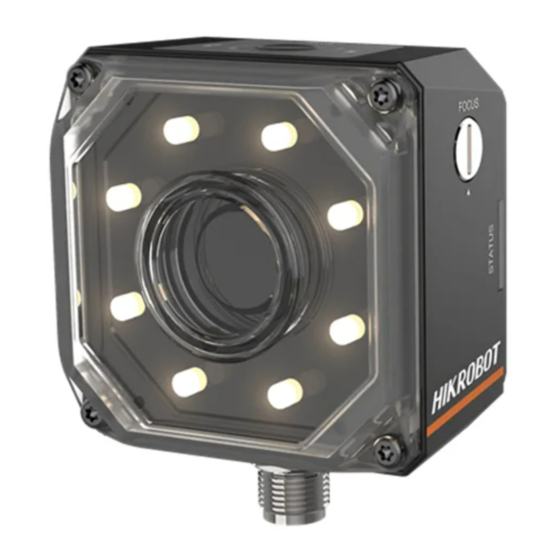
SC2000 Series Vision Sensor User Manual Chapter 2 Appearance Figure 2-1 Appearance Table 2-1 Description Name Description It provides power, input/output, Ethernet, and serial port signal. The interface is designed with screw 17-Pin Interface threads to tighten connection between the device and cable, and thus avoiding influence caused by vibration. - Page 12 SC2000 Series Vision Sensor User Manual Name Description The device has 8 LED lamps providing light, and you can Light Source select wide-angle or spotlight lamps. White, red or blue lamp is optional. It refers to the screw between device body and lens Screw cap.
-
Page 13: Chapter 3 Interface Description
SC2000 Series Vision Sensor User Manual Chapter 3 Interface Description 3.1 17-Pin Interface Read the following section to get definitions of 17-pin interface. Figure 3-1 17-Pin Interface Table 3-1 Pin Definitions Signal I/O Signal Source Description POWER_IN Direct current power supply positive... -
Page 14: Rs-232 Interface
SC2000 Series Vision Sensor User Manual Signal I/O Signal Source Description DI_0 Line 0 signal line Opto-isolated input DI_1 Line 1 signal line Opto-isolated input Note ● You should refer to the table above and the label attached to the power and I/O cable to wire the device. - Page 15 SC2000 Series Vision Sensor User Manual Figure 3-4 25-Pin Interface Table 3-2 RS-232 Interface Description Serial Port Type Pin No. Name 9-Pin Interface 25-Pin Interface...
-
Page 16: Chapter 4 I/O Wiring
SC2000 Series Vision Sensor User Manual Chapter 4 I/O Wiring 4.1 Input Signal The device's Line 0/1 is input signal, and Line 2/3/4 are bi-directional I/O(s) that can be set as input signal. The internal circuit of input signal is as follows. -
Page 17: Output Signal
SC2000 Series Vision Sensor User Manual Table 4-1 Input Electrical Feature Parameter Name Parameter Symbol Value 0 VDC to 9 VDC (VCC=24 VDC) Input Logic Level Low 0 VDC to 5.4 VDC (VCC=12 VDC) 11 VDC to 24 VDC (VCC=24... - Page 18 SC2000 Series Vision Sensor User Manual Figure 4-3 Internal Circuit of PNP Output Signal Figure 4-4 Internal Circuit of NPN Output Signal Figure 4-5 Output Logic Level When the external voltage and resistance is 12 VDC and 1 KΩ respectively, opto-isolated output electrical feature is as follows.
-
Page 19: Input Signal Wiring
SC2000 Series Vision Sensor User Manual Table 4-2 Output Electrical Feature Parameter Name Parameter Symbol Value Output Logic Level Low 212 mV Output Logic Level High 11.8 VDC Output Falling Delay 0.4 μs Output Rising Delay 0.4 μs Output Falling Time 0.4 μs... -
Page 20: Output Signal Wiring
SC2000 Series Vision Sensor User Manual Figure 4-7 Input Signal Connecting to NPN Device Switch Note It is recommended to use 330 Ω pull-down resistor. Figure 4-8 Input Signal Connecting to a Switch 4.4 Output Signal Wiring The device can output signal to external device via I/O interface, and here we take one line as an example to introduce output signal wiring. - Page 21 SC2000 Series Vision Sensor User Manual Figure 4-9 Device Outputs PNP When the device output signal is NPN, its wiring with PNP device is as follows. Figure 4-10 Device Outputs NPN Note When the device's output signal is set as NPN, the voltage of VCC should not higher than that of...
-
Page 22: Chapter 5 Installation
SC2000 Series Vision Sensor User Manual Chapter 5 Installation 5.1 Installation Preparation You need to prepare following accessories before installation. Table 5-1 Accessories Name Quantity Description It refers to the supplied 17-pin cable that is 17-Pin Cable included in the package. -
Page 23: Install Client Software
● Check the Windows version. The client software is compatible with 32/64-bit Windows XP/7/10. ● You can mail to tech_support@hikrobot.com to get client software installation package. ● The graphic user interface may differ by different versions of client software you use. -
Page 24: Chapter 6 Network Settings
SC2000 Series Vision Sensor User Manual Chapter 6 Network Settings 6.1 Set PC Network To ensure stable image transmission and normal communication between the PC and the camera via client software, you need to set the PC network before using the client software. -
Page 25: Connect Camera To Client Software
SC2000 Series Vision Sensor User Manual 1) Go to NIC settings page: Control Panel → Hardware and Sound → Device Manager → Network Adapter. 2) Select corresponding network interface card, and click Link Speed. 3) Set Speed and Duplex as Auto-Negotiation or 100 Mbps. -
Page 26: Chapter 7 Access Device Via Web Browser
SC2000 Series Vision Sensor User Manual Chapter 7 Access Device via Web Browser This section introduces how to access the device via web browser, and you can configure and operate different solutions of vision sensor as well as set system parameters. -
Page 27: Web Layout Introduction
SC2000 Series Vision Sensor User Manual 2. Check Admin, enter password, and click Login. Note The default password of admin is Abc1234. When logging in for the first time, we highly recommend you to change the password in accordance with prompt to increase security. - Page 28 SC2000 Series Vision Sensor User Manual Area Name Description It is used to display the operation result after Image Display executing current solution. The solution setting module is used to configure different solutions. Figure 7-4 Solution Setting Module Table 7-2 Description of Solution Setting Module...
- Page 29 SC2000 Series Vision Sensor User Manual Figure 7-5 System Module...
-
Page 30: Chapter 8 Solution Settings
SC2000 Series Vision Sensor User Manual Chapter 8 Solution Settings In solution settings module, if you want to configure a solution, you need to set camera parameters, tool parameters, output parameters, and save solution in finish interface. 8.1 Camera Settings 8.1.1 Set Frame Rate... -
Page 31: Set Exposure Mode
SC2000 Series Vision Sensor User Manual When the gain mode is set as OFF, and enter gain value manually. ONCE When the gain mode is set as ONCE, the device adjusts the gain automatically once according to the image brightness. -
Page 32: Set Image
SC2000 Series Vision Sensor User Manual can control all 8 light bulbs. Enable After enabling, the light bulbs you selected in Direction will turn on. Flash Mode It includes FLASH_STROBE and FLASH_LONG. Duration It refers to the duration time of light source. - Page 33 SC2000 Series Vision Sensor User Manual Width Deviation and Height Deviation It indicates the starting location of the upper left corner of the ROI area, that is, the deviation in the X direction and Y direction. This parameter adjusts the location of the ROI frame.
-
Page 34: Image Acquisition Settings
SC2000 Series Vision Sensor User Manual 8.2 Image Acquisition Settings This section introduces how to set image acquisition related parameters, such as acquisition mode, trigger mode, trigger source, etc. 8.2.1 Set Trigger Mode The device has 2 types of trigger mode, including internal trigger mode and external trigger mode. - Page 35 SC2000 Series Vision Sensor User Manual Figure 8-5 Enable External Trigger Mode Set and Execute Software Trigger Mode Steps 1. Select ON as Trigger Mode. 2. Select SOFTWARE as Trigger Source. 3. Click Software Trigger in Software Trigger to send trigger commands.
-
Page 36: Set Related Parameters About External Trigger Mode
SC2000 Series Vision Sensor User Manual Figure 8-7 Set and Execute Hardware Trigger Mode 8.2.4 Set Related Parameters about External Trigger Mode In external trigger mode, you can set 3 related parameters, including trigger activation, filter time, and trigger delay. - Page 37 SC2000 Series Vision Sensor User Manual Figure 8-8 Set Trigger Activation Set Filter Time The external trigger input signal of the device may have signal bounce that may cause false trigger. Thus, it is necessary to set filter time. Note Filter Time parameter takes effect only when you select line or button as Trigger Source.
-
Page 38: Enable Button Trigger Mode
SC2000 Series Vision Sensor User Manual Figure 8-10 Set Trigger Delay 8.2.5 Enable Button Trigger Mode The device supports triggering by pressing button on the device. Select ON as Trigger Mode, select BUTTON as Trigger Source. You can also enter Filter Time and Delay according to actual demand. -
Page 39: Input And Output (Io) Settings
SC2000 Series Vision Sensor User Manual Figure 8-12 Enable Communication Trigger Mode 8.3 Input and Output (IO) Settings Digital IO control function allows you to set input or output for specific line. Go to Solution → Camera → Trigger → Digital IO Control. - Page 40 SC2000 Series Vision Sensor User Manual Shape You can use to maximize the ROI (Region of Interest), or use to draw the ROI. Note ● Before drawing ROI, you need to stop solution operation. ● After drawing ROI, you need to click Apply.
- Page 41 SC2000 Series Vision Sensor User Manual Note For new solution, it is recommended to click Create to create feature template. Create Feature Template Steps 1. Click Create to create template. 2. Click Select Current or Select Others as template. 3. Click to create rectangle mask.
- Page 42 SC2000 Series Vision Sensor User Manual Load Feature Template Steps 1. Go to Solution → Tool → Template, and click Upload to upload local template to create feature template. Parameter Settings Min. Match Score The match score refers to the similarity between feature template and targets in the searched images.
- Page 43 SC2000 Series Vision Sensor User Manual Figure 8-16 Parameter Settings Result Display In display area, you can set different judge methods of image detection result, including quantity, angle, scale, etc. In Judge Method, enable Judge by Quantity, Judge by Angle, Judge by Scale, Judge by Score, Judge by Match Point X, Judge by Match Point Y, Judge by Center Point X, Judge by Center Point Y, and enter corresponding range according to actual demands.
-
Page 44: Fixture Settings
SC2000 Series Vision Sensor User Manual Figure 8-17 Result Display 8.4.2 Fixture Settings Fixture is a tool for assisting the positioning and correcting the target motion deviation. The position deviation reference can be set up according to the matching point and the matching frame angle in the template matching result. -
Page 45: Find Circle
SC2000 Series Vision Sensor User Manual Figure 8-18 Fixture Settings Result Display In Image Display, click to display or not display running point and reference point. Click edit OK color, NG color, and transparency. Figure 8-19 Result Display 8.4.3 Find Circle This tool detects multiple edge points first, and then fits them into a circle. - Page 46 SC2000 Series Vision Sensor User Manual ● The ROI can be rectangle only. Fixture After enabling it, you can subscribe fixture tool. See Fixture Settings for details. Note If you want to use fixture tool in finding circle, you should set fixture tool first.
- Page 47 SC2000 Series Vision Sensor User Manual Edge Polarity It has three modes, including White to Black, Black to White, and Any. White to Black refers to the transition from the area with a low gray value to the edge of the area with a high gray value.
- Page 48 SC2000 Series Vision Sensor User Manual It has three types, including Least Squares, huber and tukey. As the number of outliers and the distance from the group increases, it is recommended to use least squares, huber, and tukey successively. Start Angle It refers to the start angle of circle ROI.
-
Page 49: Find Line
SC2000 Series Vision Sensor User Manual Figure 8-22 Result Display 8.4.4 Find Line This tool finds a line with certain features in the image, and it uses known feature points to form feature point group, and then fits into a line. - Page 50 SC2000 Series Vision Sensor User Manual Note If you want to use fixture tool in finding line, you should set fixture tool first. Figure 8-23 Find Line Parameter Settings Search Mode It has three modes, including Best Line, First Line and Last Line. Best Line refers to find the set of edge points with the largest gradient threshold, and then fit them into a line within scan area.
- Page 51 SC2000 Series Vision Sensor User Manual threshold is larger than this value can be detected. The larger the value, the stronger noise resistibility, the smaller the number of edges obtained, and even the target edge points are filtered out. Edge Width It means the edge span.
- Page 52 SC2000 Series Vision Sensor User Manual Figure 8-24 Parameter Settings Result Display In display area, you can set different judge methods of image detection result, including fit points and angle. In Judge Method, enable Judge by Fit Points, Judge by Angle, and enter corresponding range according to actual demands.
-
Page 53: Find Edge Width
SC2000 Series Vision Sensor User Manual Figure 8-25 Result Display 8.4.5 Find Edge Width This tool finds edges, and measures spacing between two edges in accordance with ROI direction. Image Source By default, the image source is the images acquired by the device. - Page 54 SC2000 Series Vision Sensor User Manual Figure 8-26 Find Edge Width Parameter Settings Filter Kernel Half-Width It is used to enhance the edge and suppress noise, and its min. value is 1. When the edge is blurred or there is noise interference, you can increase its value to make the detection result more stable.
- Page 55 SC2000 Series Vision Sensor User Manual Searching Mode It has 9 modes, including Widest, Narrowest, Strongest, Weakest, First, Last, Closest, Keep Away, and All. Widest means that the edge pair that has the largest spacing within the detection range. Narrowest means that the edge pair that has the smallest spacing within the detection range.
-
Page 56: Brightness Measure
SC2000 Series Vision Sensor User Manual width, etc. In Judge Method, enable Judge by Quantity, Judge by Width, Judge by X Axis of Edge Point 0, Judge by Y Axis of Edge Point 0, , X Judgment of Edge Point 1, Y Judgment of Edge Point 1, and enter corresponding range according to actual demands. - Page 57 SC2000 Series Vision Sensor User Manual ● The ROI can be rectangle only. Fixture After enabling it, you can subscribe fixture tool. See Fixture Settings for details. Note If you want to use fixture tool in measuring brightness, you should set fixture tool first.
-
Page 58: Blob
SC2000 Series Vision Sensor User Manual Figure 8-30 Result Display 8.4.7 Blob Blob analysis means that the process of detecting, locating, or analyzing the target object in an image region where the pixel is a finite grayscale. The Blob analysis tool provides certain features of the target object in the image, such as presence, quantity, position, shape, direction, and topological relation between Blobs. - Page 59 SC2000 Series Vision Sensor User Manual Note If you want to use fixture tool in blob, you should set fixture tool first. Figure 8-31 Blob Parameter Settings Threshold Method When the input image is a binary image, it is optional to not execute binarization. In other cases, there are 4 options, including No Binarization, Single Threshold, Double Threshold, and Auto Threshold.
- Page 60 SC2000 Series Vision Sensor User Manual Enable Area After enabling area, you can set the area range where Blob will be searched. Enable Circumference After enabling circumference, you can set the circumference range where Blob will be searched. Enable Short Axis After enabling it, you can enter the range of short axis.
- Page 61 SC2000 Series Vision Sensor User Manual Figure 8-32 Connectivity Figure 8-33 Parameter Settings Result Display In display area, you can set different judge methods of image detection result, including Blob quantity, Blob area, centroid X, centroid Y, angle, center X, center Y, etc.
-
Page 62: L2L Measure
SC2000 Series Vision Sensor User Manual In Image Display, click to display or not display Blob and detection area. Click to edit OK color, NG color, and transparency. In OSD, enable Display Test to set text's color, front size, transparency, position X, and position Y. - Page 63 SC2000 Series Vision Sensor User Manual line's start point, and end point. X Coordinate of End Point If you select by coordinate as input method, you need to link the X and Y coordinates of the line's start point, and end point.
-
Page 64: Format Tool
SC2000 Series Vision Sensor User Manual Figure 8-36 Result Display 8.4.9 Format Tool This tool is used to integrate and format data, and output string at last. Go to Solution → Output → Logic Tool → Format, and double click Format to open it. -
Page 65: Logic Tool
SC2000 Series Vision Sensor User Manual Figure 8-37 Format Tool 8.4.10 Logic Tool This tool allows you to select different logical operation types and execute logic operation. Go to Solution → Output → Logic Tool → Logic, and double click Logic to open it. -
Page 66: Communication Settings
SC2000 Series Vision Sensor User Manual Figure 8-38 Logic Tool 8.5 Communication Settings The communication settings determine how the device outputs data, and you can go to Solution → Output → Communication Tool to select different communication tools according to actual demands. -
Page 67: Tcp Client
SC2000 Series Vision Sensor User Manual Figure 8-39 UDP 8.5.2 TCP Client In basic parameter interface, set output information as Input Variable, and enter Target IP and Target Port according to actual solution demands. Note Input Variable currently supports format result data or result of other communication tools. -
Page 68: Tcp Server
SC2000 Series Vision Sensor User Manual Figure 8-40 TCP Client 8.5.3 TCP Server In basic parameter interface, set output information as Input Variable, and enter Local IP and Local Port according to actual solution demands. Note Input Variable currently supports format result data or result of other communication tools. -
Page 69: Serial
SC2000 Series Vision Sensor User Manual Figure 8-41 TCP Server 8.5.4 Serial In basic parameter interface, set output information as Input Variable, and enter Serial Port Mode, Baud Rate, Parity Bit and Stop Bit according to actual solution demands. Note ●... -
Page 70: Io Communication
SC2000 Series Vision Sensor User Manual Figure 8-42 Serial 8.5.5 IO Communication The IO communication allows you to output solution result via IO. The device has 3 configurable outputs, including IO5, IO6, and IO7. You can also go to Solution → Camera → Trigger → Digital IO Control, select LINE2, LINE3, or LINE4 as IO Control, and select OUTPUT as IO Mode to add line to IO communication. -
Page 71: Ftp
SC2000 Series Vision Sensor User Manual the device will output. Output (NG) means when the solution result is NG, the device will output. NPN/PNP It sets output signal as NPN Mode or PNP Mode. In display interface, enable Display Test to set text's color, front size, transparency, position X, and position Y. -
Page 72: Solution Completion
SC2000 Series Vision Sensor User Manual It sets when to save images. It includes Not Save Image, Save Image (OK), Save Image (NG), and Save Image (OK&NG). Frame Index If you use image saving function, you can enable frame index to save the image frame number. - Page 73 SC2000 Series Vision Sensor User Manual Note After creating a new solution, if you do not change the default solution name (unnamed_solution), you cannot save it. In Enable Running Items, you can set the solution continuous running interval. Note It only takes effect when the Trigger Mode is OFF.
-
Page 74: Chapter 9 Solution Operation
SC2000 Series Vision Sensor User Manual Chapter 9 Solution Operation In basic information module, you can operate and switch different saved solutions, view device information, etc. 9.1 Control Solution The solution control is used to control solution operation or not, and display solution result. -
Page 75: Manage Solution
SC2000 Series Vision Sensor User Manual Run time refers to the device running time from powering on to current solution operation. When the solution is not operating, operating time stops. When the solution continues to operate or load other solutions, it continues to operate. -
Page 76: View Camera Info
SC2000 Series Vision Sensor User Manual The DI stands for digital IO, and it switches solution via external trigger signal. The trigger source includes LINE0, LINE1, LINE2, LINE3 and LINE4, and each trigger source can link one solution only. After enabling DI, set Trigger Source and Trigger Type, and enter Filter Time according to actual demands. - Page 77 SC2000 Series Vision Sensor User Manual Table 9-3 Icon Description Icon Description Click it to download the image to the PC. The default format is JPG. Click it to zoom out the displayed image. It displays the current image scaling ratio.
-
Page 78: Chapter 10 System And Maintenance
SC2000 Series Vision Sensor User Manual Chapter 10 System and Maintenance 10.1 Permission and Password Management In user management module, you can edit administrator password, set technician password and permission, etc. 10.1.1 Set Admin Password User management module allows you to edit admin password, set technician password and its permission to different operation modules. -
Page 79: Set Technician Permission And Password
SC2000 Series Vision Sensor User Manual 10.1.2 Set Technician Permission and Password When logging in as admin, you have the permission to set technician password and its permission to different operation modules. Note ● The admin can access to all operation and tool modules via web, and assign module operation permission to technician, while technician can access to and set module parameters assigned by the admin only. -
Page 80: Synchronize Time
SC2000 Series Vision Sensor User Manual 2. Select upgrade file from the local PC, and click OK. Figure 10-3 Update Firmware 10.3 Synchronize Time Time synchronization allows you to synchronize device time with that of local PC or server. It consists of auto mode by Network Time Protocol (NTP) server and manual mode. -
Page 81: Restore Defaults
SC2000 Series Vision Sensor User Manual Figure 10-5 NTP 10.4 Restore Defaults Restoring defaults allows you to restore the device to factory settings. Note Device solutions will be deleted after restoring defaults. You may log in again, and the admin password will be the default one (Abc1234). -
Page 82: View Log
SC2000 Series Vision Sensor User Manual 10.5 View Log Log module allows you to view device and web operation records. Click System → Log, click Refresh and view log information. Figure 10-7 View Log 10.6 View System Version About and help module allows you to view system version. -
Page 83: Chapter 11 Faq (Frequently Asked Question)
SC2000 Series Vision Sensor User Manual Chapter 11 FAQ (Frequently Asked Question) 11.1 Why the client software cannot list cameras? Reason ● Device is not started up normally. ● Network connection exception occurs. Solution ● Check device power wiring (observe PWR indicator). - Page 84 SC2000 Series Vision Sensor User Manual ● The network transmission speed is not up to 100 Mbps. Solution ● Send trigger signal to device, or disable trigger mode. ● Check if the network transmission speed is up to 100 Mbps.
- Page 85 UD17329B...
Need help?
Do you have a question about the SC2000 Series and is the answer not in the manual?
Questions and answers