HikRobot SC2000E Series Quick Start Manual
Vision sensor
Hide thumbs
Also See for SC2000E Series:
- Quick start manual (31 pages) ,
- Quick start manual (34 pages) ,
- Quick start manual (34 pages)
Table of Contents
Advertisement
Quick Links
Advertisement
Table of Contents

Subscribe to Our Youtube Channel
Related Manuals for HikRobot SC2000E Series


Summary of Contents for HikRobot SC2000E Series
- Page 1 SC2000E Series Vision Sensor Quick Start Guide...
- Page 2 INTERRUPTION, OR LOSS OF DATA, CORRUPTION OF SYSTEMS, OR LOSS OF DOCUMENTATION, WHETHER BASED ON BREACH OF CONTRACT, TORT (INCLUDING NEGLIGENCE), PRODUCT LIABILITY, OR OTHERWISE, IN CONNECTION WITH THE USE OF THE PRODUCT, EVEN IF HIKROBOT HAS BEEN ADVISED OF THE POSSIBILITY OF SUCH DAMAGES OR LOSS.
- Page 3 SC2000E Series Vision Sensor Quick Start Guide THE PERFORMANCE DATA IN THIS PUBLICATION IS BASED ON HIKROBOT'S INTERNAL RESEARCH/EVALUATION. ACTUAL DATA MAY VARY DEPENDING ON SPECIFIC CONFIGURATIONS AND OPERATING CONDITIONS AND HIKROBOT SHALL NOT BEAR THE CONSEQUENCES ARISING THEREFROM. IN THE EVENT OF ANY CONFLICTS BETWEEN THIS MANUAL AND THE APPLICABLE LAW, THE LATTER PREVAILS.
- Page 4 Indicates a hazard with a high level of risk, which if not avoided, will result in death or serious injury. Available Model This manual is applicable to the SC2000E Series Vision Sensor. Safety Instruction These instructions are intended to ensure that the user can use the device correctly to avoid danger or property loss.
- Page 5 SC2000E Series Vision Sensor Quick Start Guide ● To reduce the risk of fire or electric shock, do not expose the device to rain or moisture. ● If the device does not work properly, please contact your dealer or the nearest service center.
- Page 6 SC2000E Series Vision Sensor Quick Start Guide ● If the device is powered on and off frequently, it is necessary to strengthen the voltage isolation, and consider adding a DC/DC isolation power supply module between the device and the adapter.
-
Page 7: Table Of Contents
SC2000E Series Vision Sensor Quick Start Guide Contents Chapter 1 Overview ..........................1 1.1 Introduction ........................... 1 1.2 Key Feature ..........................1 Chapter 2 Appearance ......................... 2 Chapter 3 17-Pin Interface and Cable ....................4 3.1 17-Pin Interface ........................4 3.2 17-Pin Cable ........................... - Page 8 SC2000E Series Vision Sensor Quick Start Guide 8.3 Why the image is very dark? ....................20 8.4 Why there is no image in live view? ................... 20 8.5 What can I do if I forget the login password? ..............21...
-
Page 9: Chapter 1 Overview
Chapter 1 Overview 1.1 Introduction With built-in positioning and measurement algorithms, SC2000E series vision sensor can detect object’s existence, count patterns and spot, etc. It can be monitored and operated via the SCMVS client. It can output results via RS-232 and Ethernet, and cooperate with other processes via IO. The vision sensor supports multiple result output methods and customized result text output. -
Page 10: Chapter 2 Appearance
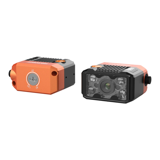
SC2000E Series Vision Sensor Quick Start Guide Chapter 2 Appearance Note Appearance here is for reference only. Refer to the device's specification for detailed dimension information. Figure 2-1 Appearance Table 2-1 Component Description Name Description Focus Knob It is used to adjust focal length manually. - Page 11 SC2000E Series Vision Sensor Quick Start Guide Name Description It is a status indicator. The indicator is green when the device operate STS Indicator normally. When errors occur during the device starts or operates, it is red. PWR Indicator It is a power indicator. The indicator is red during the device’s power-on process.
-
Page 12: Chapter 3 17-Pin Interface And Cable
SC2000E Series Vision Sensor Quick Start Guide Chapter 3 17-Pin Interface and Cable 3.1 17-Pin Interface Read the following section to get definitions of 17-pin interface. Figure 3-1 17-Pin Interface Table 3-1 Pin Definitions Signal I/O Signal Source Description Supplied Cable... -
Page 13: 17-Pin Cable
SC2000E Series Vision Sensor Quick Start Guide Signal I/O Signal Source Description Supplied Cable Purple open cable MDI0- Fast Ethernet signal MDI0- RJ45 connector MDI1+ Fast Ethernet signal MDI1+ RJ45 connector GPIO0 Line 0+ Bi-directional I/O, and it is the trigger Gray open cable by default. -
Page 14: Chapter 4 Installation
SC2000E Series Vision Sensor Quick Start Guide Chapter 4 Installation 4.1 Installation Preparation You need to prepare following accessories before installation. Table 4-1 Accessories Name Quantity Description It refers to the supplied 17-pin cable that is included 17-Pin Cable in the package. -
Page 15: Chapter 5 Device Connection
SC2000E Series Vision Sensor Quick Start Guide Chapter 5 Device Connection Device connection to the client software is required for device’s configuration and remote operations. This section introduces how to install the client software, set PC and device network, connect the device to the client software, etc. -
Page 16: Turn Off Firewall
SC2000E Series Vision Sensor Quick Start Guide Figure 5-1 Set PC Network 3. Set NIC property. 1) Go to NIC settings page: Control Panel → Hardware and Sound → Device Manager → Network Adapter. 2) Select corresponding network interface card, and click Link Speed. -
Page 17: Install Client Software
SC2000E Series Vision Sensor Quick Start Guide Figure 5-2 Windows Defender Firewall 4. Click OK. 5.3 Install Client Software SCMVS is a client software for device configuration and remote operations. Note ● Check the Windows version. The client software is compatible with 32/64-bit Windows 7/10. -
Page 18: Set Device Network
SC2000E Series Vision Sensor Quick Start Guide 5.4 Set Device Network You can set and operate the device in the client software only when the device is in the same network segment with the PC where the client software is installed. - Page 19 SC2000E Series Vision Sensor Quick Start Guide Steps 1. Click the device in the device list. 2. Enter password. 3. Click to log in. Figure 5-5 Login Interface 4. (Optional) Check Remember me to remember the password if necessary. Note If you forget password, click Forgot Password in the login interface to view the device’s serial No.,...
-
Page 20: Chapter 6 Client Layout And Operation Flow
SC2000E Series Vision Sensor Quick Start Guide Chapter 6 Client Layout and Operation Flow 6.1 Main Window Introduction After logging into the client software, you can see the main window as shown below. Figure 6-1 Main Window Note ● The specific interfaces of the client software may differ by its versions. -
Page 21: Operation Flow
SC2000E Series Vision Sensor Quick Start Guide Name Description This area displays images and results under camera mode and image mode Live View Window in real time. Under image mode, you can import images into the device. You can switch languages and cameras, view the user manual and client Other Areas version information here. -
Page 22: Chapter 7 I/O And Serial Port Introduction
SC2000E Series Vision Sensor Quick Start Guide Chapter 7 I/O and Serial Port Introduction This section introduces the electrical feature and wirings of the device’s I/O and serial port. The device has two configurable bi-directional I/Os (Line 0/1), one input signal (Line 2), one output signal (Line 3), and one RS-232. -
Page 23: Output Signal
SC2000E Series Vision Sensor Quick Start Guide Parameter Name Parameter Symbol Value Input Falling Delay 200 ns Input Rising Delay 1 μs 7.2 Output Signal The device has one output signal (Line 3) and two configurable bi-directional I/Os (Line 0/1) that can be configured to output signal, and their internal circuit is shown below. -
Page 24: I/O Wiring
SC2000E Series Vision Sensor Quick Start Guide Parameter Name Parameter Symbol Value Output Logic Level High 12 VDC (external pull-up resistor) Output Falling Delay 330 ns Output Rising Delay 4.4 μs Output Falling Time 116 ns Output Rising Time 3.8 μs Relation between different external voltages and output logic level low is shown below. - Page 25 SC2000E Series Vision Sensor Quick Start Guide PNP Device If you use the pull-down resistor of the supplied 17-pin cable, the wiring is shown below. PNP Device Power Device Power Input Signal Signal Line Device Device Power Ground ● PNP Power Ground Pull-Up and Pull-Down ●...
-
Page 26: Output Wiring
SC2000E Series Vision Sensor Quick Start Guide recommended to use 1 KΩ pull-up resistor. ● NPN Device Power Device Power Input Signal ● Signal Line Device Device Power Ground ● NPN Power Ground GND of PWR and VCC Figure 7-8 Input Signal Connecting to NPN Device (External Pull-Up Resistor Used) Switch If the input signal is switch, and its wiring is shown below. -
Page 27: Rs-232 Serial Port
SC2000E Series Vision Sensor Quick Start Guide NPN Device If the VCC of NPN device is 12 VDC or 24 VDC, and the pull-up resistor of the supplied 17-pin cable is used. Device Power Pull-Up and Pull-Down NPN Device Power ●... -
Page 28: Chapter 8 Faq (Frequently Asked Question)
SC2000E Series Vision Sensor Quick Start Guide Chapter 8 FAQ (Frequently Asked Question) 8.1 Why the client software cannot list devices? Reason ● Device is not started up normally. ● Network connection exception occurs. Solution ● Check device power wiring (observe PWR indicator). - Page 29 SC2000E Series Vision Sensor Quick Start Guide Solution Send trigger signal to device or disable trigger mode. 8.5 What can I do if I forget the login password? Solution Click Forgot Password in the login interface to view the device serial No., and mail it to the technical support personnel or call them to get the corresponding resetting file.
- Page 30 UD27618B...
Need help?
Do you have a question about the SC2000E Series and is the answer not in the manual?
Questions and answers