Table of Contents
Advertisement
Advertisement
Table of Contents

Subscribe to Our Youtube Channel
Related Manuals for HikRobot SC3000 Series


Summary of Contents for HikRobot SC3000 Series
- Page 1 SC3000 Series Vision Sensor Quick Start Guide...
- Page 2 INTERRUPTION, OR LOSS OF DATA, CORRUPTION OF SYSTEMS, OR LOSS OF DOCUMENTATION, WHETHER BASED ON BREACH OF CONTRACT, TORT (INCLUDING NEGLIGENCE), PRODUCT LIABILITY, OR OTHERWISE, IN CONNECTION WITH THE USE OF THE PRODUCT, EVEN IF HIKROBOT HAS BEEN ADVISED OF THE POSSIBILITY OF SUCH DAMAGES OR LOSS.
- Page 3 SC3000 Series Vision Sensor Quick Start Guide THE PERFORMANCE DATA IN THIS PUBLICATION IS BASED ON HIKROBOT'S INTERNAL RESEARCH/EVALUATION. ACTUAL DATA MAY VARY DEPENDING ON SPECIFIC CONFIGURATIONS AND OPERATING CONDITIONS AND HIKROBOT SHALL NOT BEAR THE CONSEQUENCES ARISING THEREFROM. IN THE EVENT OF ANY CONFLICTS BETWEEN THIS MANUAL AND THE APPLICABLE LAW, THE LATER PREVAILS.
- Page 4 Indicates a hazard with a high level of risk, which if not avoided, will result in death or serious injury. Available Model This manual is applicable to the SC3000 Series Vision Sensor. Safety Instruction These instructions are intended to ensure that the user can use the product correctly to avoid danger or property loss.
- Page 5 SC3000 Series Vision Sensor Quick Start Guide Transportation ● The product contains precision optical components and electronic components. During transportation, storage and installation, incorrect operations like heavy pressure and violent vibration should be avoided. Otherwise, the product may be damaged.
- Page 6 SC3000 Series Vision Sensor Quick Start Guide returned to the manufacturer for processing. The company does not bear any liability for accidental damage during transportation caused by non-original packaging. ● This product is a precision electronic device, no components can be maintained by user, please do not disassemble the device arbitrarily.
-
Page 7: Table Of Contents
SC3000 Series Vision Sensor Quick Start Guide Contents Chapter 1 Overview........................1 1.1 Introduction ........................... 1 1.2 Key Feature ..........................1 Chapter 2 Appearance ........................ 2 Chapter 3 17-Pin Interface ......................4 Chapter 4 Installation ......................... 6 4.1 Installation Preparation ......................6 4.2 Install Device ......................... - Page 8 SC3000 Series Vision Sensor Quick Start Guide 8.2 Why the image is not smooth in live view? ............... 22 8.3 Why the image is very dark? ....................22 8.4 Why there is no image in live view? ................... 22 8.5 What can I do if I forget the login password? ..............23...
-
Page 9: Chapter 1 Overview
Chapter 1 Overview 1.1 Introduction With built-in positioning and measurement algorithms, SC3000 series vision sensor can detect object’s existence, position, dimension, color, etc. It can be monitored and operated via the SCMVS client. It can output results via RS-232 and Ethernet, and cooperate with other processes via IO. The vision sensor supports multiple result output methods and customized result text output. -
Page 10: Chapter 2 Appearance
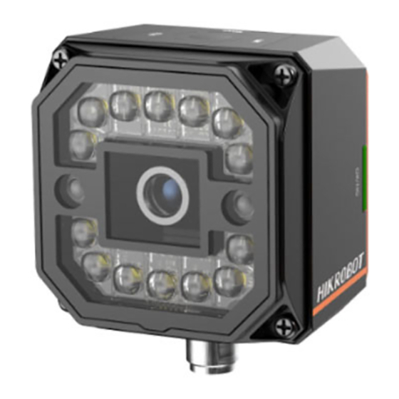
SC3000 Series Vision Sensor Quick Start Guide Chapter 2 Appearance Note Appearance here is for reference only. Refer to the device's specification for detailed dimension information. Figure 2-1 Appearance Table 2-1 Appearance Description Name Description It provides power, input/output, Ethernet, and serial port signal. The... - Page 11 SC3000 Series Vision Sensor Quick Start Guide Name Description It indicates the result of projects. ● The indicators are green when the project result is OK. ● The indicators are red when the project result is NG. OK/NG Indicator ● The indicators are green and red when switching projects. After switching, the indicators are unlit.
-
Page 12: Chapter 3 17-Pin Interface
SC3000 Series Vision Sensor Quick Start Guide Chapter 3 17-Pin Interface Read the following section to get definitions of 17-pin interface. Figure 3-1 17-Pin Interface Table 3-1 Pin Definitions Signal I/O Signal Source Description Cable Color POWER_IN Direct current power supply positive... - Page 13 SC3000 Series Vision Sensor Quick Start Guide Signal I/O Signal Source Description Cable Color MDI1+ Fast Ethernet signal MDI1+ Orange DI_0 Line 0 signal line Opto-isolated input Gray DI_1 Line 1 signal line Opto-isolated input White Note ● You should refer to the table above and the label attached to the power and I/O cable to wire the device.
-
Page 14: Chapter 4 Installation
SC3000 Series Vision Sensor Quick Start Guide Chapter 4 Installation 4.1 Installation Preparation You need to prepare following accessories before installation. Table 4-1 Accessories Name Quantity Description It refers to the supplied 17-pin cable that is included 17-Pin Cable in the package. -
Page 15: Chapter 5 Device Connection
SC3000 Series Vision Sensor Quick Start Guide Chapter 5 Device Connection Device connection to the client software is required for device’s configuration and remote operations. This section introduces how to install the client software, set PC and device network, connect the device to the client software, etc. -
Page 16: Turn Off Firewall
SC3000 Series Vision Sensor Quick Start Guide 5.2 Turn off Firewall To ensure stable client running and image transmission, you are recommended turning off Windows firewall before using the client software. Steps Note For different Windows versions, the path name or interface may differ. Please refer to the actual condition. -
Page 17: Set Device Network
SC3000 Series Vision Sensor Quick Start Guide Select Obtain an IP address automatically to get an IP address of the PC automatically. Or select Use the following IP address to set an IP address for the PC manually. -
Page 18: Login
SC3000 Series Vision Sensor Quick Start Guide Figure 5-4 Edit IP Address 6. Click OK. 5.5 Login Note ● Make sure that your device IP address is in the same network segment with the PC where you installed the client software before connecting the device to it. - Page 19 SC3000 Series Vision Sensor Quick Start Guide Figure 5-5 Login Interface 4. (Optional) Check Remember me to remember the password if necessary.
-
Page 20: Chapter 6 Client Layout And Operation Flow
SC3000 Series Vision Sensor Quick Start Guide Chapter 6 Client Layout and Operation Flow 6.1 Main Window Introduction After logging into the client software, you can see the main window as shown below. Figure 6-1 Main Window Note ● The specific interfaces of the client software may differ by its versions. -
Page 21: Operation Flow
SC3000 Series Vision Sensor Quick Start Guide Name Description This area displays images and results under camera mode and image mode Live View Window in real time. Under image mode, you can import images into the device. You can switch languages and cameras, view the user manual and client Other Areas version information here. -
Page 22: Chapter 7 I/O And Serial Port Introduction
SC3000 Series Vision Sensor Quick Start Guide Chapter 7 I/O and Serial Port Introduction This section introduces the electrical feature and wirings of the device’s I/O and RS-232 serial port. The device has two input signals (Line 0/1), three output signals (Line 5/6/7), and three bi-directional I/O (Line 2/3/4) signals. -
Page 23: Output Signal
SC3000 Series Vision Sensor Quick Start Guide Figure 7-2 Input Logic Level Table 7-1 Input Electrical Feature Parameter Name Parameter Symbol Value 0 VDC to 9 VDC (VCC=24 VDC) Input Logic Level Low 0 VDC to 5.4 VDC (VCC=12 VDC) - Page 24 SC3000 Series Vision Sensor Quick Start Guide Figure 7-3 Set I/O Output Type Note The maximum output current of output signal is 200 mA. If the output signal is PNP type, its internal circuit is shown below. Figure 7-4 Internal Circuit of PNP Output Signal...
- Page 25 SC3000 Series Vision Sensor Quick Start Guide If the output signal is NPN type, its internal circuit is shown below. Figure 7-5 Internal Circuit of NPN Output Signal Figure 7-6 Output Logic Level When the external voltage and resistance is 12 VDC and 1 KΩ respectively, the electrical feature of output signal is as follows.
-
Page 26: I/O Wiring
SC3000 Series Vision Sensor Quick Start Guide Parameter Name Parameter Symbol Value Output Falling Time 0.4 μs Output Rising Time 0.4 μs 7.2 I/O Wiring The device can receive input signals from external devices and output signals to external devices. - Page 27 SC3000 Series Vision Sensor Quick Start Guide NPN Device If you have available external resistors, and the VCC is 12 VDC or 24 VDC, you should use 1 KΩ pull- up resistor to wire the device as shown below. Figure 7-8 Input Signal Connects to NPN Device Switch It is recommended to use 1 KΩ...
-
Page 28: Output Wiring
SC3000 Series Vision Sensor Quick Start Guide NPN Device If you do not have available external resistors, you can wire the device as shown below. NPN Device Device Power Power IN_COM Input Signal Signal Line Device Device Power NPN Device... -
Page 29: Introduction
SC3000 Series Vision Sensor Quick Start Guide the client software to set related parameters. 7.3.1 Introduction The 9-pin male connector and 25-pin male connector are commonly used serial ports, as shown below. You can refer to the table below for the specific pin name and function. -
Page 30: Chapter 8 Faq (Frequently Asked Question)
SC3000 Series Vision Sensor Quick Start Guide Chapter 8 FAQ (Frequently Asked Question) 8.1 Why the client software cannot list devices? Reason ● Device is not started up normally. ● Network connection exception occurs. Solution ● Check device power wiring (observe PWR indicator). - Page 31 SC3000 Series Vision Sensor Quick Start Guide ● The network transmission speed is not up to 100 Mbps. Solution ● Send trigger signal to device, or disable trigger mode. ● Check if the network transmission speed is up to 100 Mbps.
- Page 32 UD24212B...
Need help?
Do you have a question about the SC3000 Series and is the answer not in the manual?
Questions and answers