Table of Contents
Advertisement
Advertisement
Table of Contents

Subscribe to Our Youtube Channel
Related Manuals for HikRobot SC2000 Series


Summary of Contents for HikRobot SC2000 Series
- Page 1 SC2000 Series Vision Sensor User Manual...
- Page 2 INTERRUPTION, OR LOSS OF DATA, CORRUPTION OF SYSTEMS, OR LOSS OF DOCUMENTATION, WHETHER BASED ON BREACH OF CONTRACT, TORT (INCLUDING NEGLIGENCE), PRODUCT LIABILITY, OR OTHERWISE, IN CONNECTION WITH THE USE OF THE PRODUCT, EVEN IF HIKROBOT HAS BEEN ADVISED OF THE POSSIBILITY OF SUCH DAMAGES OR LOSS.
- Page 3 TO ANY NUCLEAR EXPLOSIVE OR UNSAFE NUCLEAR FUEL-CYCLE, OR IN SUPPORT OF HUMAN RIGHTS ABUSES. THE PERFORMANCE DATA IN THIS PUBLICATION IS BASED ON HIKROBOT'S INTERNAL RESEARCH/EVALUATION. ACTUAL DATA MAY VARY DEPENDING ON SPECIFIC CONFIGURATIONS AND OPERATING CONDITIONS AND HIKROBOT SHALL NOT BEAR THE CONSEQUENCES ARISING THEREFROM.
- Page 4 Note important points of the main text. Available Model This manual is applicable to the SC2000 Series Vision Sensor. Safety Instruction These instructions are intended to ensure that the user can use the device correctly to avoid danger or property loss.
- Page 5 SC2000 Series Vision Sensor User Manual Power Supply ● When wiring or dismounting, make sure that the device power is cut off, and do not operate under electrification. ● Avoid contact with exposed circuit. When the device is powered on, avoid contact with exposed junctions and parts.
- Page 6 SC2000 Series Vision Sensor User Manual ● It is suggested to place humidifier in dry environment to maintain suitable humidity and reduce static electricity generation. Maintenance ● If the device is not working properly, contact the store or the nearest service center. Do not disassemble or modify the device in any way.
-
Page 7: Table Of Contents
SC2000 Series Vision Sensor User Manual Contents Chapter 1 Overview ........................1 1.1 Introduction ........................1 1.2 Key Feature ........................1 Chapter 2 Appearance ........................2 Chapter 3 17-Pin Interface ......................4 Chapter 4 I/O Wiring ........................6 4.1 Input ..........................6 4.2 Output .......................... - Page 8 SC2000 Series Vision Sensor User Manual 7.2.4 Set Related Parameters about External Trigger Mode ......... 23 7.2.5 Enable Communication Trigger Mode ..............24 7.3 Input and Output (IO) Settings ..................25 7.4 Tool Settings ........................25 7.4.1 Feature Matching ....................26 7.4.2 Fixture Settings ....................
- Page 9 SC2000 Series Vision Sensor User Manual 7.5.9 Ethernet/IP ......................57 7.6 Solution Completion ....................... 57 Chapter 8 Solution Operation....................... 59 8.1 Control Solution ......................59 8.2 View Solution Status ....................... 59 8.3 Manage Solution ......................60 8.4 View Camera Info......................61 8.5 Operate Image ........................
-
Page 10: Chapter 1 Overview
SC2000 Series Vision Sensor User Manual Chapter 1 Overview 1.1 Introduction The vision sensor uses the sensor and optical components to acquire object images, and it adopts built-in location and measurement algorithms to detect object's dimension, location, etc. It has multiple vision tools, such as, feature matching, blob, calibration transformation, color extraction, etc., to realize different applications. -
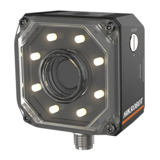
Page 11: Chapter 2 Appearance
SC2000 Series Vision Sensor User Manual Chapter 2 Appearance Figure 2-1 Appearance Table 2-1 Description Name Description It provides power, input/output, Ethernet, and serial port signal. The interface is designed with screw threads to tighten 17-Pin Interface connection between the device and cable, and thus avoiding influence caused by vibration. - Page 12 SC2000 Series Vision Sensor User Manual Name Description The device has 8 LED lamps providing light, and the light source is Light Source white spotlight by default. You can select wide-angle or spotlight lamp, and white, red, blue or near-infrared is optional.
-
Page 13: Chapter 3 17-Pin Interface
SC2000 Series Vision Sensor User Manual Chapter 3 17-Pin Interface Read the following section to get definitions of 17-pin interface. Figure 3-1 17-Pin Interface Table 3-1 Pin Definitions Signal I/O Signal Source Description POWER_IN Direct current power supply positive I/O_1... - Page 14 SC2000 Series Vision Sensor User Manual Signal I/O Signal Source Description DI_0 Line 0 signal line Opto-isolated input DI_1 Line 1 signal line Opto-isolated input Note ● You should refer to the table above and the label attached to the power and I/O cable to wire the device.
-
Page 15: Chapter 4 I/O Wiring
SC2000 Series Vision Sensor User Manual Chapter 4 I/O Wiring 4.1 Input The device's Line 0/1 is input, and Line 2/3/4 are bi-directional I/O(s) that can be set as input. The internal circuit of input signal is as follows. Note The maximum input current of input signal is 25 mA. -
Page 16: Output
SC2000 Series Vision Sensor User Manual Table 4-1 Input Electrical Feature Parameter Name Parameter Symbol Value 0 VDC to 9 VDC (VCC=24 VDC) Input Logic Level Low 0 VDC to 5.4 VDC (VCC=12 VDC) 11 VDC to 24 VDC (VCC=24... - Page 17 SC2000 Series Vision Sensor User Manual Figure 4-3 Internal Circuit of PNP Output Signal Figure 4-4 Internal Circuit of NPN Output Signal Figure 4-5 Output Logic Level When the external voltage and resistance is 12 VDC and 1 KΩ respectively, opto-isolated output electrical feature is as follows.
-
Page 18: Input Wiring
SC2000 Series Vision Sensor User Manual Table 4-2 Output Electrical Feature Parameter Name Parameter Symbol Value Output Logic Level Low 212 mV Output Logic Level High 11.8 VDC Output Falling Delay 0.4 μs Output Rising Delay 0.4 μs Output Falling Time 0.4 μs... -
Page 19: Output Wiring
SC2000 Series Vision Sensor User Manual Figure 4-7 Input Signal Connecting to NPN Device Switch Note It is recommended to use 1 KΩ pull-down resistor. Figure 4-8 Input Signal Connecting to a Switch 4.4 Output Wiring The device can output signal to external device via I/O interface, and here we take one line as an example to introduce output signal wiring. -
Page 20: Rs-232 Serial Port
SC2000 Series Vision Sensor User Manual Figure 4-9 Device Outputs PNP Signal When the device output signal is NPN, it is recommended to use 1 KΩ pull-up resistor if PNP device is connected. Figure 4-10 Device Outputs NPN Signal Note When the device's output signal is set as NPN, the voltage of VCC should not higher than that of PWR. - Page 21 SC2000 Series Vision Sensor User Manual Figure 4-12 25-Pin Male Connector Table 4-3 RS-232 Interface Description Serial Port Type Pin No. Name Function Receive data 9-Pin Interface Send data Signal ground Send data 25-Pin Interface Receive data Signal ground You can refer to the serial port wiring below to connect the device with an external device.
-
Page 22: Chapter 5 Installation
SC2000 Series Vision Sensor User Manual Chapter 5 Installation 5.1 Installation Preparation You need to prepare following accessories before installation. Table 5-1 Accessories Name Quantity Description It refers to the supplied 17-pin cable that is 17-Pin Cable included in the package. -
Page 23: Chapter 6 Access Device Via Web Browser
SC2000 Series Vision Sensor User Manual Chapter 6 Access Device via Web Browser 2 ways are available to access the device via the web browser: You can enter the IP address of the device in the web browser to access the device, or use the Camera Search tool to search the device and access it via the web. - Page 24 SC2000 Series Vision Sensor User Manual Figure 6-1 Access via Web Browser After the browser is opened, you need to check Admin, enter the password, and click Login. Note ● The default password of the admin is Abc1234. ● The browser should support HTML5 and the Chrome is recommended.
-
Page 25: Chapter 7 Solution Settings
SC2000 Series Vision Sensor User Manual Chapter 7 Solution Settings The vision sensor is able to acquire, process and output images. You can log in the web interface to set camera parameters, tool parameters, output parameters, etc. After competing related settings, you can save and download the solution you configured. -
Page 26: Set Gain
SC2000 Series Vision Sensor User Manual 7.1.2 Set Gain The device supports 3 types of Gain Mode, including OFF, ONCE and CONTINUOUS. When the gain mode is set as OFF, you can enter the gain value manually. ONCE When the gain mode is set as ONCE, the device adjusts the gain automatically once according to the image brightness. -
Page 27: Set Light Source
SC2000 Series Vision Sensor User Manual 7.1.5 Set Light Source The device has 8 light bulbs, and you can go to Light Source Adjustment to set light direction, flash mode, duration, delay, etc. Direction The device has 8 light bulbs, which are divided into up, down, left and right groups. You can select UP, DOWN, LEFT and RIGHT to control respective light bulbs. -
Page 28: Set Image
SC2000 Series Vision Sensor User Manual 7.1.6 Set Image Go to Image to set image related parameters. Pixel Format The mono device supports Mono 8 only, and the color device supports Mono 8 and RGB. Width It refers to the image width, and you can adjust it according to actual demands. - Page 29 SC2000 Series Vision Sensor User Manual Figure 7-3 Set Image CCM Reset Note This parameter is only available for the color device and rgb is selected as pixel format. CCM stands for Color Correction Matrix, and it is used to help improve inter-instrument agreement in display and light sources measurements.
-
Page 30: Image Acquisition Settings
SC2000 Series Vision Sensor User Manual Note This parameter is only available for the color device and rgb is selected as pixel format. AWB stands for Automatic White Balance, and the device adjusts color according to different light sources. If you want to use AWB function, you should enable AWB Enable first. -
Page 31: Enable External Trigger Mode
SC2000 Series Vision Sensor User Manual Note OFF refers to the internal trigger mode. 7.2.3 Enable External Trigger Mode Go to Trigger Mode to select ON as Trigger Mode. Note ON refers to the external trigger mode. Set and Execute Software Trigger Mode Steps 1. -
Page 32: Set Related Parameters About External Trigger Mode
SC2000 Series Vision Sensor User Manual Figure 7-7 Set and Execute Hardware Trigger Mode 7.2.4 Set Related Parameters about External Trigger Mode Note Parameter settings may differ when selecting different trigger sources. In external trigger mode, you can also set related parameters, including trigger cache, trigger type, trigger delay, and filter time. -
Page 33: Enable Communication Trigger Mode
SC2000 Series Vision Sensor User Manual The level high of the trigger signal is valid. As long as the trigger signal is in level high, the device is in image acquisition status. Level Low The level low of the trigger signal is valid. As long as the trigger signal is in level low, the device is in image acquisition status. -
Page 34: Input And Output (Io) Settings
SC2000 Series Vision Sensor User Manual Figure 7-9 Enable Communication Trigger 7.3 Input and Output (IO) Settings Digital IO control function allows you to set input or output for specific line. Go to Digital IO Control, select specific lines as IO Control according to actual demands, and set INPUT or OUTPUT as IO Mode for the line selected in IO Control. -
Page 35: Feature Matching
SC2000 Series Vision Sensor User Manual ROI Settings For most tools, you need to set image source and ROI area in basic parameter interface before setting specific operating parameters. Image source is the images acquired by the device by default. ROI area allows you to create or reuse certain areas, you can select different shapes to draw directly, or select different reuse methods to determine the ROI. - Page 36 SC2000 Series Vision Sensor User Manual 4. Click to select the matching point location, and move the blue cross in the image to the ideal location. 5. Click to create template. 6. Optional: Click to download the current template to the PC.
- Page 37 SC2000 Series Vision Sensor User Manual It includes No Polarity and Polarity. Angle It is the angle range of searched targets. The edited template is the reference. Scale Zoom in and zoom out with same scale. It is applied for the target and template with certain percentage.
-
Page 38: Fixture Settings
SC2000 Series Vision Sensor User Manual Result Display In display area, you can set different judge methods of image detection result, including quantity, angle, scale, etc. In Judge Method, enable Judge by Quantity, Judge by Angle, Judge by Scale, Judge by Score, Judge by Match Point X, Judge by Match Point Y, Judge by Center Point X, Judge by Center Point Y, and enter corresponding range according to actual demands. -
Page 39: Find Circle
SC2000 Series Vision Sensor User Manual Figure 7-14 Fixture Settings Result Display In Image Display, click to display or not display running point and reference point. Click edit OK color, NG color, and transparency. 7.4.3 Find Circle This tool detects multiple edge points first, and then fits them into a circle. It is used to locate and measure the circle. - Page 40 SC2000 Series Vision Sensor User Manual threshold is larger than this value can be detected. The larger the value, the stronger noise resistibility, the smaller the number of edges obtained, and even the target edge points are filtered out. Filter Size It is used to enhance the edge and suppress noise, and its min.
-
Page 41: Find Line
SC2000 Series Vision Sensor User Manual Figure 7-15 Set Operating Parameters Result Display In display area, you can set different judge methods of image detection result, including radius, center X, center Y, fit error, etc. In Judge Method, enable Judge by Radius, Judge by Center X, Judge by Center Y, Judge by Fit Error, Judge by Fit Points, and enter corresponding range according to actual demands. - Page 42 SC2000 Series Vision Sensor User Manual and them into a line within scan area. The Last refers to find the set of edge points that have the closest distance with ending point and them into a line within scan area.
-
Page 43: Brightness Measure
SC2000 Series Vision Sensor User Manual Figure 7-16 Set Operating Parameters Result Display In display area, you can set different judge methods of image detection result, including fit points and angle. In Judge Method, enable Judge by Fit Points, Judge by Angle, and enter corresponding range according to actual demands. -
Page 44: Blob
SC2000 Series Vision Sensor User Manual In Image Display, click to display or not display detection area. Click to edit OK color, NG color, and transparency. In OSD, enable Display Text to set text's color, front size, transparency, position X, and position Y. - Page 45 SC2000 Series Vision Sensor User Manual Enable Circularity After enabling circularity, you can set circularity range where Blob will be searched. Enable Rectangularity After enabling rectangularity, you can set rectangularity range where Blob will be searched. Enable Centroid Offset It refers to the absolute pixel offset between the Blob centroid and the minimum area of the Blob circumscribed rectangle.
-
Page 46: Find Edge Width
SC2000 Series Vision Sensor User Manual Figure 7-18 Set Operating Parameters 7.4.7 Find Edge Width This tool finds edges, and measures spacing between two edges in accordance with ROI direction. Parameter Settings Filter Kernel Half-Width It is used to enhance the edge and suppress noise, and its min. value is 1. When the edge is blurred or there is noise interference, you can increase its value to make the detection result more stable. - Page 47 SC2000 Series Vision Sensor User Manual Searching Mode It includes Widest, Narrowest, Strongest, Weakest, First, Last, etc. Searching Mode It has 9 modes, including Widest, Narrowest, Strongest, Weakest, First, Last, Closest, Least Close, and All. Widest means that the edge pair that has the largest spacing within the detection range.
-
Page 48: L2L Measure
SC2000 Series Vision Sensor User Manual In Image Display, click to display or not display edge 0 result, edge 1 result, edge line result and detection area. Click to edit OK color, NG color, and transparency. In OSD, enable Display Text to set text's color, front size, transparency, position X, and position Y. -
Page 49: P2L Measure
SC2000 Series Vision Sensor User Manual 7.4.9 P2L Measure This tool is used to measure the distance between a pint and a line, and calculate the actual distance between them. You need to enter the specific information like coordinates of the point and line. -
Page 50: N-Point Calibration
SC2000 Series Vision Sensor User Manual After Image Source and Input Status are linked, you should select the Save Mode, Picture Format (RAW, BMP, JPG), and Image Saving according to actual demands. You can enable Frame No., Trigger No., and Result to save the current image’s related information. - Page 51 SC2000 Series Vision Sensor User Manual Number and Rotation Number. You can also click in Edit Calibration Point to edit the image coordinate, the physical coordinate and angle information. Physical Coordinate Parameters Reference Point X/Y refers to the physical coordinates of the calibration origin, and it is recommended to set them as (0, 0).
-
Page 52: Coordinate Conversion
SC2000 Series Vision Sensor User Manual If Ransac is selected, you need to set Distance Threshold and Sampling Ratio according to actual demands. Distance Threshold refers to the distance threshold for eliminating the error point. When the point group's accuracy is not high, this threshold can be appropriately increased. When the point group's accuracy is not high, the sampling ratio can be appropriately reduced. -
Page 53: Color Extraction
SC2000 Series Vision Sensor User Manual Figure 7-25 Coordinate Conversion 7.4.13 Color Extraction Note This tool is available for color vison sensors only. The color space for the color extraction can be RGB, HSV or HSI. According to the brightness of each channel to be extracted, you can set parameter ranges of different channels. -
Page 54: Color Measurement
SC2000 Series Vision Sensor User Manual Figure 7-26 Color Extraction 7.4.14 Color Measurement Note This tool is available for color vison sensors only. This tool is used to measure the color information in the specified area of the color image, including the max. -
Page 55: Color Recognition
SC2000 Series Vision Sensor User Manual Table 7-1 Conversion Type Description Conversion Type Description 0.299r + 0.587g + 0.114b. r stands for the gray value of the R channel, g stands for the gray General Ratio value of the G channel, and b stands for the gray value of the B channel. - Page 56 SC2000 Series Vision Sensor User Manual This tool relies on colors as a template for object classification and recognition. When different types of objects that have obvious color differences, this tool can be used to accurately classify objects, and output related classification information.
-
Page 57: Format Tool
SC2000 Series Vision Sensor User Manual Figure 7-29 Set Operating Parameters 7.4.17 Format Tool This tool is used to integrate and format data, and output string. In basic interface, you can click to subscribe data that is needed formatting, click to add text information, click add semicolon, and then click OK. -
Page 58: Logic Tool
SC2000 Series Vision Sensor User Manual 7.4.18 Logic Tool This tool allows you to select different logical operation types and execute logic operation. Select AND, OR, NOT, NAND or NOR as Logical Operation Type, and click to link data source or enter data directly. -
Page 59: Tcp Client
SC2000 Series Vision Sensor User Manual Figure 7-32 UDP 7.5.2 TCP Client In basic parameter interface, set output information as Input Variable, and enter Target IP and Target Port according to actual solution demands. Note Input Variable currently supports format result data or result of other communication tools. -
Page 60: Tcp Server
SC2000 Series Vision Sensor User Manual 7.5.3 TCP Server In basic parameter interface, set output information as Input Variable, and enter Local IP and Local Port according to actual solution demands. Note Input Variable currently supports format result data or result of other communication tools. -
Page 61: Io Communication
SC2000 Series Vision Sensor User Manual Figure 7-35 Serial 7.5.5 IO Communication The IO communication allows you to output solution result via IO. The device has 3 configurable outputs, including IO5, IO6, and IO7. You can also go to Solution → Camera → Trigger → Digital IO Control, select LINE2, LINE3, or LINE4 as IO Control, and select OUTPUT as IO Mode to add line to IO communication. -
Page 62: Ftp
SC2000 Series Vision Sensor User Manual It sets output signal as NPN Mode or PNP Mode. Figure 7-36 IO Communication In display interface, enable Display Text to set text's color, front size, transparency, position X, and position Y. 7.5.6 FTP In FTP communication, set the image file of the device as Image Source, and set the previous module status as Input Status. -
Page 63: Modbus
SC2000 Series Vision Sensor User Manual Start Tag and End Tag It refers to the start and end tag of image name. You can enter lowercase and uppercase letter, digit, and @ # ^ & () - _ = + . , ; '. - Page 64 SC2000 Series Vision Sensor User Manual Table 7-2 Parameter Description Parameter Description Input Settings It currently supports format result data or result of other Input Variable communication tools. Basic Info. Local IP It refers to the IP address of the vison sensor.
-
Page 65: Profinet
SC2000 Series Vision Sensor User Manual Figure 7-38 Modbus In display interface, enable Display Text to set text's color, front size, transparency, position X, and position Y. 7.5.8 Profinet Profinet is an industry technical standard for data communication over industrial Ethernet, designed for collecting data from, and controlling equipment in industrial systems, with a particular strength in delivering data under tight time constraints. -
Page 66: Ethernet/Ip
SC2000 Series Vision Sensor User Manual In display interface, enable Display Text to set text's color, front size, transparency, position X, and position Y. 7.5.9 Ethernet/IP Ethernet/IP is a network communication standard capable of handling large amounts of data at speeds of 10 Mbps or 100 Mbps, and at up to 1500 bytes per packet. - Page 67 SC2000 Series Vision Sensor User Manual Note You need to go to System → User Management → Technician → Technician Permission to enable technician permission first. In Solution Result, if you have used a logic tool in your solution, you can view and link the result of logic module to the solution.
-
Page 68: Chapter 8 Solution Operation
SC2000 Series Vision Sensor User Manual Chapter 8 Solution Operation In basic information module, you can operate and switch different saved solutions, view device information, etc. 8.1 Control Solution The solution control is used to control solution operation or not, and display solution result. -
Page 69: Manage Solution
SC2000 Series Vision Sensor User Manual Total refers to the total quantity of detected image from device powering on to now. Click reset total quantity and NG quantity. If the device is acquiring images, and resetting will stop device acquisition. -
Page 70: View Camera Info
SC2000 Series Vision Sensor User Manual The DI stands for digital IO, and it switches solution via external trigger signal. The trigger source includes line 0, line 1, line 2, line 3, line 4 and button. After enabling DI, set Trigger Source and Trigger Type, and enter Filter Time according to actual demands. - Page 71 SC2000 Series Vision Sensor User Manual Table 8-3 Icon Description Icon Description Click it to download the image to the PC. The default format is JPG. Click it to zoom out the displayed image. It displays the current image-scaling ratio.
-
Page 72: Chapter 9 System And Maintenance
SC2000 Series Vision Sensor User Manual Chapter 9 System and Maintenance 9.1 Permission and Password Management In user management module, you can edit administrator password, set technician password and permission, etc. 9.1.1 Set Admin Password User management module allows you to edit admin password, set technician password and its permission to different operation modules. -
Page 73: Image Saving Management
SC2000 Series Vision Sensor User Manual to different operation modules. Note ● The admin can access to all operation and tool modules via web, and assign module operation permission to technician, while technician can access to and set module parameters assigned by the admin only. -
Page 74: Synchronize Time
SC2000 Series Vision Sensor User Manual image related parameters. There are 2 ways to import test images, uploading local images and importing camera images. Click Upload Local Image to upload images from the local PC, and images of RAW, BMP and JPEG format are supported. -
Page 75: System Maintenance
SC2000 Series Vision Sensor User Manual Figure 9-5 Time Synchronization 9.5 System Maintenance System maintenance allows you to update firmware, restore factory, and reboot device. Firmware updating allows you to view current device firmware version, and update firmware. Note ● Make sure the device and solution stop operation when updating the firmware. -
Page 76: View Log
SC2000 Series Vision Sensor User Manual Note Device solutions will be deleted after restoring defaults. You may log in again, and the admin password will be the default one (Abc1234). Figure 9-7 Restore Factory You can also click Reboot to reboot the device. -
Page 77: View System Version
SC2000 Series Vision Sensor User Manual 9.7 View System Version About and help module allows you to view the firmware version, and web version. -
Page 78: Chapter 10 Faq (Frequently Asked Question)
SC2000 Series Vision Sensor User Manual Chapter 10 FAQ (Frequently Asked Question) 10.1 Why the client software cannot list cameras? Reason ● Device is not started up normally. ● Network connection exception occurs. Solution ● Check device power wiring (observe PWR indicator). -
Page 79: What Can I Do If I Forget The Login Password
SC2000 Series Vision Sensor User Manual ● The network transmission speed is not up to 100 Mbps. Solution ● Send trigger signal to device, or disable trigger mode. ● Check if the network transmission speed is up to 100 Mbps. -
Page 80: Chapter 11 Revision History
SC2000 Series Vision Sensor User Manual Chapter 11 Revision History Table 11-1 Description No. Version No. Document No. Date Revision Details Modify Section Access Device via UD19529B May 8, 2020 Web Browser. Add Section P2L Measure. Add Section Image Savings. - Page 81 UD19529B...
Need help?
Do you have a question about the SC2000 Series and is the answer not in the manual?
Questions and answers