Omron Sysmac NJ Series User Manual
Machine automation controller, cpu unit built-in ethercat port
Hide thumbs
Also See for Sysmac NJ Series:
- User manual (578 pages) ,
- Connection manual (56 pages) ,
- Network connection manual (32 pages)

Subscribe to Our Youtube Channel
Related Manuals for Omron Sysmac NJ Series


Summary of Contents for Omron Sysmac NJ Series
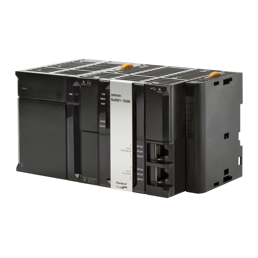
- Page 1 Machine Automation Controller NJ/NX-series CPU Unit Built-in EtherCAT Port ® User’s Manual NX701-1 NX102- NX1P2-1 NX1P2-9 NJ501- NJ301-1 NJ101-10 NJ101-90 CPU Unit W505-E1-24...
- Page 2 No patent liability is assumed with respect to the use of the information contained herein. Moreover, because OMRON is constantly striving to improve its high-quality products, the information contained in this manual is subject to change without notice. Every precaution has been taken in the preparation of this manual. Neverthe- less, OMRON assumes no responsibility for errors or omissions.
-
Page 3: Intended Audience
Introduction Introduction Thank you for purchasing an NJ/NX-series CPU Unit. This manual contains information that is necessary to use the NJ/NX-series CPU Unit. Please read this manual and make sure you understand the functionality and performance of the NJ/NX-series CPU Unit before you attempt to use it in a control system. Keep this manual in a safe place where it will be available for reference during operation. - Page 4 Introduction Part of the specifications and restrictions for the CPU Units are given in other manuals. Refer to Relevant Manuals on page 3 and Related Manuals on page 26. NJ/NX-series CPU Unit Built-in EtherCAT Port User's Manual (W505)
-
Page 5: Relevant Manuals
Relevant Manuals Relevant Manuals The following table provides the relevant manuals for the NJ/NX-series CPU Units. Read all of the manuals that are relevant to your system configuration and application before you use the NJ/NX-ser- ies CPU Unit. Most operations are performed from the Sysmac Studio Automation Software. Refer to the Sysmac Studio Version 1 Operation Manual (Cat. - Page 6 Relevant Manuals Manual Basic information Purpose of use Software settings Using motion control ¡ Using EtherCAT ¡ Using EtherNet/IP ¡ Using OPC UA ¡ Using FINS ¡ Using the database connec- ¡ tion service ¡ Using the GEM Services ¡ Using robot control for OM- ¡...
- Page 7 Relevant Manuals Manual Basic information Purpose of use Testing operation and debug- ging Using motion control ¡ Using EtherCAT ¡ Using EtherNet/IP ¡ Using OPC UA ¡ Using FINS ¡ Using the database connec- ¡ ¡ tion service Using the GEM Services ¡...
-
Page 8: Manual Structure
Manual Structure Manual Structure Page Structure The following page structure is used in this manual. Level 1 heading 4 Installation and Wiring Level 2 heading Mounting Units Level 3 heading Level 2 heading Gives the current Level 3 heading headings. 4-3-1 Connecting Controller Components The Units that make up an NJ-series Controller can be connected simply by pressing the Units together... -
Page 9: Special Information
Manual Structure Special Information Special information in this manual is classified as follows: Precautions for Safe Use Precautions on what to do and what not to do to ensure safe usage of the product. Precautions for Correct Use Precautions on what to do and what not to do to ensure proper operation and performance. Additional Information Additional information to read as required. - Page 10 Manual Structure NJ/NX-series CPU Unit Built-in EtherCAT Port User's Manual (W505)
-
Page 11: Sections In This Manual
Sections in this Manual Sections in this Manual Introduction Appendices Part Names and Index Slave Settings EtherCAT Communications EtherCAT Network Wiring Setting Up EtherCAT Communications with the Sysmac Studio Process Data Communications and SDO Communications System-defined Variables Related to the Built-in EtherCAT Port Example of Operations for EtherCAT Communications Troubleshooting NJ/NX-series CPU Unit Built-in EtherCAT Port User's Manual (W505) -
Page 12: Table Of Contents
CONTENTS CONTENTS Introduction ......................1 Intended Audience............................1 Applicable Products ............................1 Relevant Manuals..................... 3 Manual Structure...................... 6 Page Structure..............................6 Special Information ............................7 Precaution on Terminology ..........................7 Sections in this Manual ................... 9 Terms and Conditions Agreement................ 14 Warranty, Limitations of Liability ........................14 Application Considerations ..........................15 Disclaimers ..............................15 Safety Precautions.................... - Page 13 CONTENTS Section 2 Part Names and Slave Settings Part Names and Functions....................2-2 2-1-1 Built-in EtherCAT Port Indicators....................2-2 2-1-2 Windows Used in Sysmac Studio ....................2-4 2-1-3 Connecting the Sysmac Studio ....................2-7 Setting the Node Addresses of the EtherCAT Slaves ............2-9 2-2-1 Setting Node Address Using Hardware Switches ...............2-9 2-2-2 Setting the Node Address from the Sysmac Studio ..............2-10...
- Page 14 CONTENTS 5-5-1 Changing the PDO Map Settings ....................5-23 5-5-2 EtherCAT Slave Enable/Disable Settings..................5-25 Comparing and Merging EtherCAT Network Configurations ..........5-28 5-6-1 Introduction for Comparing and Merging EtherCAT Network Configurations......5-28 5-6-2 Operation Procedure for Comparing and Merging EtherCAT Network Configurations .....5-28 5-6-3 When Compare and Merge with Actual Network Configuration Dialog Box Is Not Displayed ..........................5-32...
- Page 15 Monitoring Packets....................... A-7 Multi-vendor Environments ....................A-15 A-3-1 EtherCAT Slave Information File (ESI Files) ................A-15 A-3-2 Connecting Slaves from Other Manufacturers to an OMRON Master ........A-16 A-3-3 Installing ESI files ........................A-16 A-3-4 Editing PDO Entry Tables......................A-21 A-3-5 Settings for MDP-compatible Slaves from Other Manufacturers ..........
-
Page 16: Terms And Conditions Agreement
Omron’s exclusive warranty is that the Products will be free from defects in materials and work- manship for a period of twelve months from the date of sale by Omron (or such other period ex- pressed in writing by Omron). Omron disclaims all other warranties, express or implied. -
Page 17: Application Considerations
WAY CONNECTED WITH THE PRODUCTS, WHETHER SUCH CLAIM IS BASED IN CONTRACT, WARRANTY, NEGLIGENCE OR STRICT LIABILITY. Further, in no event shall liability of Omron Companies exceed the individual price of the Product on which liability is asserted. Application Considerations... - Page 18 Product. Errors and Omissions Information presented by Omron Companies has been checked and is believed to be accurate; how- ever, no responsibility is assumed for clerical, typographical or proofreading errors or omissions. NJ/NX-series CPU Unit Built-in EtherCAT Port User's Manual (W505)
-
Page 19: Safety Precautions
Safety Precautions Safety Precautions Refer to the following manuals for safety precautions. • NX-series CPU Unit Hardware User's Manual (Cat. No. W535) • NX-series NX102 CPU Unit Hardware User's Manual (Cat. No. W593) • NX-series NX1P2 CPU Unit Hardware User's Manual (Cat. No. W578) •... -
Page 20: Precautions For Safe Use
Precautions for Safe Use Precautions for Safe Use Refer to the following manuals for precautions for safe use. • NX-series CPU Unit Hardware User's Manual (Cat. No. W535) • NX-series NX102 CPU Unit Hardware User's Manual (Cat. No. W593) • NX-series NX1P2 CPU Unit Hardware User's Manual (Cat. No. W578) •... -
Page 21: Precautions For Correct Use
Precautions for Correct Use Precautions for Correct Use Refer to the following manuals for precautions for correct use. • NX-series CPU Unit Hardware User's Manual (Cat. No. W535) • NX-series NX102 CPU Unit Hardware User's Manual (Cat. No. W593) • NX-series NX1P2 CPU Unit Hardware User's Manual (Cat. No. W578) •... -
Page 22: Regulations And Standards
Regulations and Standards Regulations and Standards Refer to the following manuals for regulations and standards. • NX-series CPU Unit Hardware User's Manual (Cat. No. W535) • NX-series NX102 CPU Unit Hardware User's Manual (Cat. No. W593) • NX-series NX1P2 CPU Unit Hardware User's Manual (Cat. No. W578) •... -
Page 23: Versions
Versions Versions Hardware revisions and unit versions are used to manage the hardware and software in NJ/NX-series Units and EtherCAT slaves. The hardware revision or unit version is updated each time there is a change in hardware or software specifications. Even when two Units or EtherCAT slaves have the same model number, they will have functional or performance differences if they have different hard- ware revisions or unit versions. - Page 24 Versions Unit version Hardware revision Lot number Serial number LOT No. DDMYY xxxx Ver. . HW Rev. PORT1 PORT2 MAC address ID Information Indication Note The hardware revision is not displayed for the Unit whose hardware revision is blank. For NX1P2 The ID information on an NX-series NX1P2-£££££££...
- Page 25 Versions ID information indication Unit model Unit version Hardware revision NJ501 - Ver.1. HW Rev. PORT1 MAC ADDRESS: PORT2 MAC ADDRESS: Lot No. DDMYY xxxx Lot number Serial number MAC address Note The hardware revision is not displayed for the Unit that the hardware revision is in blank. Checking Unit Versions with the Sysmac Studio You can use the Sysmac Studio to check unit versions.
- Page 26 Versions Changing Information Displayed in Production Information Dialog Box Click the Show Detail or Show Outline Button at the lower right of the Production Information Dialog Box. The view will change between the production information details and outline. Outline View Detail View The information that is displayed is different for the Outline View and Detail View.
-
Page 27: Unit Versions Of Cpu Units And Sysmac Studio Versions
Versions Outline View Detail View Unit Versions of CPU Units and Sysmac Studio Versions The functions that are supported depend on the unit version of the NJ/NX-series CPU Unit. The ver- sion of Sysmac Studio that supports the functions that were added for an upgrade is required to use those functions. -
Page 28: Related Manuals
Related Manuals Related Manuals The followings are the manuals related to this manual. Use these manuals for reference. Manual name Cat. No. Model numbers Application Description NX-series CPU Unit W535 NX701-££££ Learning the basic An introduction to the entire NX701 system Hardware User's Manual specifications of the is provided along with the following informa-... - Page 29 O037 NJ501-R£££ Using the NJ-series Describes the settings and operation of the Robot Integrated CPU Unit Robot Integrated CPU Unit and programming concepts for User’s Manual CPU Unit. OMRON robot control. NJ/NX-series CPU Unit Built-in EtherCAT Port User's Manual (W505)
- Page 30 Related Manuals Manual name Cat. No. Model numbers Application Description Sysmac Studio W595 SYSMAC-SE2££ Learning about the Describes the operating procedures of the Robot Integrated System operating procedures Sysmac Studio for Robot Integrated CPU £ Building Function with Robot SYSMAC- and functions of the Unit.
-
Page 31: Revision History
Revision History Revision History A manual revision code appears as a suffix to the catalog number on the front and back covers of the manual. W505-E1-24 Cat. No. Revision code Revision Date Revised content code July 2011 Original production March 2012 Added information on the NJ301-££££... - Page 32 Revision History Revision Date Revised content code • October 2017 Corrected mistakes. • April 2018 Corrected mistakes. • April 2018 Added information on the NX102-££££. • Collected descriptions on event codes and errors to the NJ/NX-series Troubleshooting Manual. • Corrected mistakes. July 2018 Corrected mistakes.
-
Page 33: Introduction
Introduction This section provides an overview of EtherCAT communications, describes the system configuration and specifications, and provides operating procedures. Introduction to EtherCAT................1-2 1-1-1 EtherCAT Features..................1-2 1-1-2 EtherCAT Communications ................1-2 1-1-3 EtherCAT Features for NJ/NX-series CPU Units ..........1-3 System Configuration and Configuration Devices ........ -
Page 34: Introduction To Ethercat
1 Introduction Introduction to EtherCAT EtherCAT (Ethernet Control Automation Technology) is a high-performance industrial network system that enables faster and more efficient communications based on Ethernet. Each node achieves a short communications cycle time by transmitting Ethernet frames at high speed. Furthermore, even though EtherCAT is a unique protocol, it offers excellent general-purpose applica- bility. -
Page 35: Ethercat Features For Nj/Nx-Series Cpu Units
You can use the NJ/NX-series Machine Automation Controllers together with Sysmac devices the Sysmac Studio Automation Software to achieve optimum functionality and ease of operation. *1. “Sysmac devices” is a generic name for EtherCAT slaves and other OMRON control components that were designed with the same communications and user interface specifications. -
Page 36: System Configuration And Configuration Devices
1 Introduction System Configuration and Configura- tion Devices 1-2-1 System Configuration The EtherCAT network configuration and configuration devices are shown below. Sysmac Studio NJ/NX-series CPU Unit EtherCAT master ESI files .xml Built-in EtherCAT port Input port EtherCAT Junction Slave Unit power supply Communications cable Output ports I/O power supply... - Page 37 Note 2. The slaves are synchronized between synced slaves even when multiple non-synced slaves and Junction Slaves are connected. The following table lists some of the OMRON EtherCAT slaves that are available. Synced Refer-...
- Page 38 1 Introduction Synced Refer- /Non- Assigning ence Name Type Model synced an axis Clock Slaves NX-series Ether- NX Series Synced Exist Not possible NX-ECC201 CAT Coupler Unit or Non- (Some of the NX-ECC202 synced connected NX-ECC203 NX Units can Slaves be assigned to an axis.) Multifunctional,...
- Page 39 • The Junction Slave supports the reference clock that is required for a system configuration that enables synchronization between slaves based on a distributed clock (DC). • The following models are examples of some of the OMRON EtherCAT slaves. Slave type/name...
-
Page 40: Determining The Network Configuration
1 Introduction Communications Cables Use a straight, shielded twisted-pair cable (double shielding with aluminum tape and braiding) of Ethernet category 5 (100BASE-TX) or higher. ESI (EtherCAT Slave Information) File The ESI files contain information unique to the EtherCAT slaves in XML format. You can load an ESI file into the Sysmac Studio, to easily allocate slave process data and make other settings. - Page 41 1 Introduction Precautions for Safe Use • You cannot use standard Ethernet hubs or repeater hubs with EtherCAT communications. If you use one of these, a major fault level error or other error may occur. • Make sure that the communications distance, number of devices connected, and method of connection for EtherCAT are within specifications.
-
Page 42: Specifications Of Built-In Ethercat Port
1 Introduction Specifications of Built-in EtherCAT Port Specification Item NX1P2-£££££ NJ501-££££/ NX701-££££ NX102-££££ NJ101-££££ ££ NJ301-££££ Communications EtherCAT protocol protocol Supported serv- CoE (Process data communications and SDO communications) ices Synchronization DC (Distributed Clock) Physical layer 100BASE-TX Modulation Baseband Baud rate 100 Mbit/s (100BASE-TX) Auto Duplex mode... - Page 43 1 Introduction Connection is possible only in full duplex mode. Half-duplex connections will result in link OFF status. A ring topology can be used for project unit version 1.40 or later. The maximum number of slaves in 8 for an NX1P2-9B£££££ CPU Unit. However, the data must be within eight frames.
-
Page 44: Overview Of Communications
1 Introduction Overview of Communications This section provides an overview of the communications functions of the built-in EtherCAT port. 1-4-1 Process Data Communications and SDO Communications The built-in EtherCAT port performs the following communications method to exchange information with EtherCAT slaves. •... - Page 45 1 Introduction Network Configurations and Setup Enable/Disable Setting for Slaves Use this function to select the EtherCAT slaves for communications with from among those regis- tered in the network configuration information. • You can design a network with future addition of EtherCAT slaves in mind, by setting EtherCAT slaves that you plan to add at a later time to Disabled and then registering them in the network configuration information on the EtherCAT master.
- Page 46 1 Introduction You enable/disable the fail-soft operation in Sysmac Studio. Refer to 5-4 EtherCAT Master Parame- ter Settings on page 5-14 for the setting procedure. Maintenance Disconnecting/Reconnecting Slaves Use this function to temporarily stop and start process data communications with a specified slave. It is useful because, during system operation, you can replace an erroneous EtherCAT slave with- out interrupting the communications with EtherCAT slaves that are operating normally.
-
Page 47: Ethercat Communications Procedure
1 Introduction EtherCAT Communications Proce- dure 1-5-1 Overview Step Section Mounting and Setting Devices and Hardware 2-2 Setting the Node Addresses of the EtherCAT Slaves on page 2-9 Laying EtherCAT Communications Cables Section 4 EtherCAT Network Wiring on page 4-1 Creating the EtherCAT Network Configuration 5-2 Creating the EtherCAT Network Config- uration on page 5-3... - Page 48 1 Introduction Sysmac Studio opera- Step Description Section tion • Mounting and Setting Use the hardware switches on all of the Ether- 2-2 Setting Devices and Hardware CAT slaves in the network to set the node ad- the Node Addresses dresses.
- Page 49 1 Introduction Sysmac Studio opera- Step Description Section tion Setting EtherCAT Mas- Set the EtherCAT master parameters. Set an EtherCAT mas- 5-4 Ether- ter Parameters (Examples: Fail-soft Operation Setting and Wait ter with EtherCAT un- CAT Mas- Time for Slave Startup) der Configurations ter Param- The values that are set are reflected in the net-...
- Page 50 1 Introduction Sysmac Studio opera- Step Description Section tion Downloading the Net- Download the network configuration information Select 5-9 Down- work Configuration In- (EtherCAT configuration, process data informa- Synchronization from loading the formation and the User tion, and parameters). the Controller Menu to Network Note Use the synchronization operation of the Program...
- Page 51 Part Names and Slave Settings This section provides the part names and describes the slave settings and Sysmac device functions. Part Names and Functions ................2-2 2-1-1 Built-in EtherCAT Port Indicators..............2-2 2-1-2 Windows Used in Sysmac Studio..............2-4 2-1-3 Connecting the Sysmac Studio ...............
-
Page 52: Part Names And Functions
2 Part Names and Slave Settings Part Names and Functions 2-1-1 Built-in EtherCAT Port Indicators The indicators show the operating status of the built-in EtherCAT port on an NJ/NX-series CPU Unit. The locations of indicators of the built-in EtherCAT port on the CPU Unit as well as the colors and sta- tuses of indicators associated with corresponding operating status are shown below. - Page 53 2 Part Names and Slave Settings NX102 CPU Unit Operation indicators for the Built-in EtherCAT port Built-in EtherCAT port (PORT3) NX1P2 CPU Unit POWER PORT1 EtherNet/IP ERROR BUSY SD PWR SD BUSY PORT1 EtherNet/IP NET RUN PORT2 EtherCAT NET ERR LINK/ACT PORT2 EtherCAT...
-
Page 54: Windows Used In Sysmac Studio
2 Part Names and Slave Settings Label Color Status Meaning NET RUN Gree EtherCAT communications are in progress. • Inputs and outputs for I/O data are in operation. Flashing EtherCAT communications are being established. This indicator shows either of the following conditions. •... - Page 55 2 Part Names and Slave Settings Setting EtherCAT Slave Variables and Axes • I/O Map: Used to allocate device variables. Use the I/O Map to assign device variables to the I/O ports of the EtherCAT slaves. • Axis Basic Settings: Used to create Axis Variables and set parameters for Servo Drive and en- coder input slaves.
- Page 56 2 Part Names and Slave Settings • Setting Axis Parameters: Use the Axis Setting Table to set axis parameters. EtherCAT Master and Slave Parameter Settings Set the EtherCAT master and slave parameters after selecting a master or slave on the EtherCAT network configuration.
-
Page 57: Connecting The Sysmac Studio
2 Part Names and Slave Settings • Parameter Setting for the EtherCAT Slaves Refer to Section 5 Setting Up EtherCAT Communications with the Sysmac Studio on page 5-1 for the Sysmac Studio procedures. 2-1-3 Connecting the Sysmac Studio You can connect the Sysmac Studio to the NJ/NX-series CPU Unit through the USB or EtherNet/IP port. - Page 58 2 Part Names and Slave Settings Select the connection method for the connection configuration in the Connection type Area. If you select Remote connection via USB or Ethernet connection via a hub, enter the IP address of the Controller in the Remote IP Address Area. Also set Options and Response Monitor Time if necessary.
-
Page 59: Setting The Node Addresses Of The Ethercat Slaves
Errors in the EtherCAT Master Function Module in the NJ/NX-series Troubleshooting Manual (Cat. No. W503). • If you use an OMRON EtherCAT slave, after setting the node address, you need to cycle the power supply to the slave to apply the setting. -
Page 60: Setting The Node Address From The Sysmac Studio
2 Part Names and Slave Settings 2-2-2 Setting the Node Address from the Sysmac Studio Use the Sysmac Studio to set the node address if there are no hardware switches or the node address is beyond the range that can be set with the hardware switches. ... - Page 61 2 Part Names and Slave Settings If there are slaves for which the node address is not set (i.e., for which the present value is 0) or if there is more than one slave with the same node address (indicated by ), change the set values of the slave addresses, and then click the Write Button.
-
Page 62: Features Of Sysmac Devices
2-3-1 Sysmac Devices "Sysmac devices" is a generic name for EtherCAT slaves and other OMRON control components that were designed with the same communications and user interface specifications. You can use the NJ/NX-series Machine Automation Controllers together with Sysmac devices and the Sysmac Studio Automation Software to achieve optimum functionality and ease of operation. - Page 63 2 Part Names and Slave Settings Additional Information • This feature is not supported for OMRON slaves that are not Sysmac devices and slaves that are manufactured by other companies. Check the error detection methods for each slave. • Before you reset an error from the NJ/NX-series EtherCAT master, make sure you confirm the cause of the error in the slave.
-
Page 64: List Of Sysmac Devices
2-3-3 List of Sysmac Devices The following table lists the OMRON Sysmac slaves. Refer to relevant manuals for each slave for in- formation on OMRON slaves that are not listed in the following table. 2-14 NJ/NX-series CPU Unit Built-in EtherCAT Port User's Manual (W505) -
Page 65: Sysmac Device Features And Ethercat Masters
A CPU Unit with unit version 1.07 or later and Sysmac Studio version 1.11 or higher are required. 2-3-4 Sysmac Device Features and EtherCAT Masters The following table shows the relationship between Sysmac device features and EtherCAT masters. OMRON Sysmac Device Slaves OMRON EtherCAT master NJ/NX-series CPU Unit NX701-££££... - Page 66 The node address setting method depends on the EtherCAT master from another manufacturer that you use. Whether the serial number can be checked or not depends on the EtherCAT master from another manufac- turer that you use. OMRON Slaves That Do Not Support Sysmac Devices OMRON EtherCAT master NJ/NX-series CPU Unit NX701-££££...
- Page 67 Slaves from Other Manufacturers If you connect slaves from other manufacturers to an OMRON EtherCAT master, functionality is re- stricted as given below depending on the functionality of the slaves. • Some items for slave function setting may be missing or the slave functionality may be restricted with an ESI file that is not supported by Sysmac Studio.
- Page 68 2 Part Names and Slave Settings 2-18 NJ/NX-series CPU Unit Built-in EtherCAT Port User's Manual (W505)
- Page 69 EtherCAT Communications This section describes the different types of EtherCAT communications, EtherCAT set- tings, and state transitions. EtherCAT Communications Types and Settings ......... 3-2 3-1-1 CoE (CAN Application Protocol over EtherCAT) ..........3-2 3-1-2 Types of Communications ................3-4 3-1-3 Types of EtherCAT Variables................
-
Page 70: Ethercat Communications
3 EtherCAT Communications EtherCAT Communications Types and Settings 3-1-1 CoE (CAN Application Protocol over EtherCAT) The EtherCAT port built into the NJ/NX-series CPU Unit uses CoE (CAN application protocol over EtherCAT) to exchange information with slaves over EtherCAT. CoE implements message communications of CAN application over an EtherCAT network. With CoE, the parameters and control information held by the slaves are specified according to data specifications for the object dictionary. - Page 71 3 EtherCAT Communications Additional Information Object Dictionary The object dictionary is a data table within the device that interfaces the application and com- munications. It describes the information handled by the device. Each piece of information is called an object. Each object is assigned a 4-digit hexadecimal index.
-
Page 72: Types Of Communications
3 EtherCAT Communications Additional Information Distributed Clock (DC) This is a unique EtherCAT feature that enables precisely clock synchronization. The DC-based clock synchronization enables sharing the same time between the EtherCAT master and the slaves. This enables the timing of the operation of the EtherCAT master and slaves to be synchronized with the shared time. - Page 73 3 EtherCAT Communications CPU Unit EtherCAT communications Cyclic communications (for PDO data) Process data communications: Device Constant data exchange variables and (process data communications cycle) Axis Variables* Message communications (for SDO data) EC_CoESDORead/ EC_CoESDOWrite EtherCAT SDO communications: data data When required (from instruction or Sysmac Studio) SDO data...
-
Page 74: Types Of Ethercat Variables
3 EtherCAT Communications 3-1-3 Types of EtherCAT Variables There are three types of EtherCAT variables as listed below. Variable type Description Allocated var- Device varia- These are common in-out variables for EtherCAT slaves. You can change the iables bles names of these variables. Device variables for I/O ports CPU Unit... -
Page 75: Settings Required For Ethercat Communications
3 EtherCAT Communications 3-1-4 Settings Required for EtherCAT Communications For EtherCAT communications, you must set the following network configuration information from the Sysmac Studio and download it to the CPU Unit. • Network configuration: Master and slave configuration • EtherCAT master settings: Parameters settings, such as the Fail-soft Operation Setting or Wait Time for Slave Startup •... -
Page 76: Programming Ethercat Communications
3 EtherCAT Communications Programming EtherCAT Communica- tions The user program in the NJ/NX-series CPU Unit reads/writes EtherCAT slave data and performs mo- tion control for Servo Drive and encoder input slaves. Instructions and variables are used according to slave types and target data as shown below. Slave type Type of data Timing... -
Page 77: State Transitions For Ethercat Communications
3 EtherCAT Communications State Transitions for EtherCAT Com- munications 3-3-1 Self Diagnosis at Startup The EtherCAT master executes the following self-diagnosis when the power is turned ON. The results of self-diagnosis are provided in the following events and system-defined variables as EtherCAT master errors if errors are detected. - Page 78 3 EtherCAT Communications Afterwards, EtherCAT communications are performed while the state changes automatically between these states according to error occurrence and other conditions. The current control state can be determined using the RUN indicator on the front panel. Process data SDO com- RUN indi- State...
-
Page 79: Ethercat Status In Relation To Cpu Unit Status
3 EtherCAT Communications Additional Information I/O Refreshing The procedure from startup of the EtherCAT network until process data I/O can be refreshed is shown below. There is no correlation between the startup of the EtherCAT network and the execution of the user program. - Page 80 3 EtherCAT Communications 3-12 NJ/NX-series CPU Unit Built-in EtherCAT Port User's Manual (W505)
-
Page 81: Ethercat Network Wiring
EtherCAT Network Wiring This section describes how to connect and wire an EtherCAT network. Supported Network Topologies ..............4-2 4-1-1 Line/Daisy Chain Topology................4-2 4-1-2 Branching Topology..................4-2 4-1-3 Ring Topology....................4-4 4-1-4 Precautions for Using Junction Slaves............4-10 Laying the EtherCAT Network..............4-12 4-2-1 Installation Precautions ................. -
Page 82: Supported Network Topologies
4 EtherCAT Network Wiring Supported Network Topologies The NJ/NX-series CPU Units support line/daisy chain, branching, and ring topologies. You can com- bine more than one topology. Each of these topologies is described below. 4-1-1 Line/Daisy Chain Topology This topology connects the output ports and input ports of slaves one after another in a row. EtherCAT master Slave Input port... - Page 83 4 EtherCAT Network Wiring Slave Slave GX-JC06 Junction Slave EtherCAT master Slave GX-JC03 Junction Slave Slave Slave Input port Output port Features of Branching Topology In a configuration that consists of only a line/daisy chain topology, if a slave is disconnected due to a broken cable or other reason, all slaves after the disconnected slave are also disconnected from the network.
-
Page 84: Ring Topology
4 EtherCAT Network Wiring 4-1-3 Ring Topology This topology uses Junction Slaves to connect slaves in a ring. This section describes the features, components, and precautions for the ring topology. Version Information Project unit version 1.40 or later and Sysmac Studio version 1.29 or higher are required to use the ring topology. - Page 85 4 EtherCAT Network Wiring Precautions for Correct Use • If there is more than one point of disconnection in the communications cables in the ring top- ology, the master stops communications with slaves to which the communications paths are broken with the Junction Slave. It continues communications with other slaves. In this case, an Illegal Slave Disconnection Detected (84310002 hex) event occurs.
- Page 86 Sysmac Studio. Refer to 5-2-2 Cable Redundancy Setting on page 5-5 for how to set Cable Redundancy to Enable. b. You can use more than one Junction Slave in a ring topology. Use the OMRON GX-JC03 Ether- CAT Junction Slave.
- Page 87 4 EtherCAT Network Wiring EtherCAT master Slave A :Can be connected with synced slaves :Cannot be connected with synced slaves Ring topology GX-JC03 Originating slave of the ring Junction Slave Slave B Drop line from the ring GX-JC03 Junction Slave Slave C Slave D Input port...
- Page 88 4 EtherCAT Network Wiring EtherCAT master :Can be connected with synced slaves :Cannot be connected with synced slaves Synced Slave GX-JC06 Junction Slave A Synced Slave Ring topology GX-JC03 Originating slave GX-JC06 Junction Slave C Junction Slave B of the ring Non-synced Slave Non-synced Slave Synced Slave...
- Page 89 4 EtherCAT Network Wiring EtherCAT master Ring topology Originating slave GX-JC03 Junction Slave of the ring Slave Slave Start port of the ring End port of the ring GX-JC03 Junction Slave Last port Slave Last slave Input port Output port Example for Configuring Drop Line from the Ring with Junction Slaves You can connect Junction Slaves in a ring topology to configure a drop line from the ring.
-
Page 90: Precautions For Using Junction Slaves
4 EtherCAT Network Wiring EtherCAT master Ring topology GX-JC03 Junction Slave Drop line from the ring Slave Slave GX-JC03 Junction Slave Slave Input port Output port 4-1-4 Precautions for Using Junction Slaves This section provides precautions for using Junction Slaves in a network configuration based on the branching or ring topology. - Page 91 You can determine whether the EtherCAT Junction Slave supports a reference clock from the Reference Clock in the slave settings on the Sysmac Studio. OMRON EtherCAT Junction Slaves support a reference clock. Precautions for Correct Use For project unit version 1.40 or later, check that the EtherCAT Junction Slave ports actually con- nected to slaves agree with the ports of the network configuration information on the Sysmac Studio.
-
Page 92: Laying The Ethercat Network
4 EtherCAT Network Wiring Laying the EtherCAT Network This section describes how to install EtherCAT networks. 4-2-1 Installation Precautions Basic precautions for the installation of EtherCAT networks are provided below. Precautions when Installing a Network • When you install an EtherCAT network, take sufficient safety precautions and perform the installa- tion according to standards and specifications. -
Page 93: Installing Ethercat Communications Cables
Size and Conductor Pairs: AWG27 × 4 Pairs Manufac- Cable Contact infor- Product name Model turer length [m] mation Cable with Connectors on OMRON XS6W-6LSZH8SS30CM-Y OMRON Cus- Both Ends Corpora- tomer Service XS6W-6LSZH8SS50CM-Y (RJ45/RJ45) tion Center XS6W-6LSZH8SS100CM-Y Standard RJ45 plugs XS6W-6LSZH8SS200CM-Y Cable Sheath material:... - Page 94 Cables are available in the following lengths: 0.3, 0.5, 1, 2, 3, 5, 10, and 15 m. Refer to the Industrial Ethernet Connectors Catalog (Cat. No. G019) for details. For details, contact your OMRON representative. Cables are available from 0.25 m to 100 m. Ask the manufacturer for details on the models that are not described in the table.
- Page 95 Kuramo Electric Co., Ltd. JMACS Japan Co., Ltd. PNET/B* JMACS Japan Co., Ltd. RJ45 Assembly Con- OMRON Corporation XS6G-T421-1* OMRON Customer Serv- nectors ice Center * We recommend that you use combinations of the above Cables and Connectors. Part name Manufacturer Model...
-
Page 96: Connecting Communications Cables
4 EtherCAT Network Wiring Attaching the Connectors to the Cable and Pin Assignments Use straight wiring to attach the connectors to the communications cable. Pin No. Wire color Wire color Pin No. White-Green White-Green Green Green White-Orange White-Orange Blue Blue White-Blue White-Blue Orange... - Page 97 4 EtherCAT Network Wiring EtherCAT master Communications cable Input port Output port Slaves Do not connect anything Last slave The cable between the EtherCAT master and a slave and between any two slaves (L1, L2 ... Ln) must be 100 m or less. Firmly connect the communications cable connector until it clicks into place.
-
Page 98: Cable Connection Procedure
4 EtherCAT Network Wiring 4-2-4 Cable Connection Procedure Precautions for Correct Use • Turn OFF the Controller's power supply before connecting or disconnecting Ethernet commu- nications cable. • Allow extra space for the bending radius of the communications cable. The required space depends on the communications cable, connector, and CPU Unit that are used. -
Page 99: Setting Up Ethercat Communications With The Sysmac Studio
Setting Up EtherCAT Communica- tions with the Sysmac Studio This section describes how to set the network configuration information and how to check EtherCAT communications from the Sysmac Studio. Overview of Network Configuration Information ........5-2 Creating the EtherCAT Network Configuration ........... 5-3 5-2-1 Procedure to Create the EtherCAT Network Configuration ...... -
Page 100: Overview Of Network Configuration Information
5 Setting Up EtherCAT Communications with the Sysmac Studio Overview of Network Configuration Information To execute EtherCAT communications, you must create the following three types of data with the Sys- mac Studio and download the data to the CPU Unit. When this data is set, the network configuration information is automatically created. -
Page 101: Creating The Ethercat Network Configuration
5 Setting Up EtherCAT Communications with the Sysmac Studio Creating the EtherCAT Network Con- figuration This section describes how to create the EtherCAT network configuration. 5-2-1 Procedure to Create the EtherCAT Network Configuration Start the Sysmac Studio offline. Double-click EtherCAT under Configurations and Setup on the Multiview Explorer. Or, right- click EtherCAT under Configurations and Setup and select Edit. - Page 102 5 Setting Up EtherCAT Communications with the Sysmac Studio EtherCAT Tab Page Select a slave in the Toolbox, drag it to the EtherCAT Tab Page, and drop it to the master. The slave will be added under the master. Toolbox Drag the slaves.
-
Page 103: Cable Redundancy Setting
5 Setting Up EtherCAT Communications with the Sysmac Studio • For detailed procedures, such as those for deleting slaves, or copying and pasting slaves, refer to the Sysmac Studio Version 1 Operation Manual (Cat. No. W504). • Refer to the NX-series EtherCAT Coupler Units User’s Manual (Cat. No. W519) and the Sysmac Studio Version 1 Operation Manual (Cat. - Page 104 5 Setting Up EtherCAT Communications with the Sysmac Studio Operation of the Cable Redundancy Function The operation of the cable redundancy function is described below. • If there is only one point of disconnection in the communications cables in a ring topology and its state changes from the cable redundancy status to the ring disconnection status, a Ring Disconnection Detected (84390000 hex) event occurs and the state of the communications cables and the point of disconnection are provided in the following system-defined variables.
- Page 105 5 Setting Up EtherCAT Communications with the Sysmac Studio Start port of the ring. Connect the slave to the start port of the ring. Precautions for Correct Use Do not connect the slave to the end port of the ring X3 that becomes the end point of the ring topology.
- Page 106 5 Setting Up EtherCAT Communications with the Sysmac Studio As shown below, "Redundancy" is indicated and double lines are displayed on the location where the cable redundancy is enabled. NJ/NX-series CPU Unit Built-in EtherCAT Port User's Manual (W505)
-
Page 107: Setting Ethercat Slave Variables And Axes
5 Setting Up EtherCAT Communications with the Sysmac Studio Setting EtherCAT Slave Variables and Axes Device variables are used to read and write process data for EtherCAT slaves. Axis variables are used to manipulate slaves to which axes are assigned from the Motion Control Function Module. This sec- tion describes how to register device variables and set the axes. - Page 108 5 Setting Up EtherCAT Communications with the Sysmac Studio Select the variables from the pull-down list in the I/O Map Tab Page to assign them to I/O ports. Select user-defined variables that were previously registered in the global variable table. Inputting New Device Variable Names You can input the required device variable names.
- Page 109 5 Setting Up EtherCAT Communications with the Sysmac Studio Select the I/O port on the I/O Map Tag Page and enter the variable name in the Variable Col- umn. Device variables are assigned to the I/O ports of the slaves. To specify a variable table for the scope, specify the Variable Type.
- Page 110 5 Setting Up EtherCAT Communications with the Sysmac Studio The device names are set in the slave parameters. The default device names are E followed by a serial number that starts from 001. For example, this method can be used to register device variables in the following cases. •...
-
Page 111: Axis Settings For Servo Drives And Encoder Input Slaves
5 Setting Up EtherCAT Communications with the Sysmac Studio Device variables are automatically assigned to the I/O ports of the slaves and registered in the variable table that is specified by the Variable Type. Additional Information • We recommend that you set the device names. •... -
Page 112: Ethercat Master Parameter Settings
5 Setting Up EtherCAT Communications with the Sysmac Studio EtherCAT Master Parameter Settings Double-click EtherCAT under Configurations and Setup on the Multiview Explorer. Or, right- click EtherCAT under Configurations and Setup and select Edit. Select the EtherCAT master that is displayed in the Edit Pane. •... - Page 113 5 Setting Up EtherCAT Communications with the Sysmac Studio The above screen is for NX701 CPU Units. The EtherCAT master settings are listed below. Edit- Name Remarks Device name Displays the name of the EtherCAT master. Default setting: Master Model name Always ”Master.”...
- Page 114 5 Setting Up EtherCAT Communications with the Sysmac Studio Edit- Name Remarks Sets the transmission delay time that is a parameter used to cal- Transmission Delay Time culate the I/O refresh time. Selects the transmission delay time for each PDO communica- tions cycle from the following values.
- Page 115 5 Setting Up EtherCAT Communications with the Sysmac Studio Edit- Name Remarks Revision Check Method Specifies the method to use to verify the revision numbers that are stored in the network configuration information (setting) against the actual revision numbers of the slaves (actual device) at the start of communications.
- Page 116 5 Setting Up EtherCAT Communications with the Sysmac Studio *13. If you enable the cable redundancy in the network configuration, set a value other than No check. *14. If the set value is Setting = Actual device, communications are not started with a slave, in a network, that is replaced.
- Page 117 5 Setting Up EtherCAT Communications with the Sysmac Studio Additional Information Network Configuration Verification The network configuration information is verified against the actual network when the EtherCAT master is started. If an inconsistency is found during verification, a Network Configuration Verification Error (84220000 hex) or Network Configuration Verification Error (Mismatched Slave) (84330004 hex) event will occur.
-
Page 118: Ethercat Slave Parameter Settings
5 Setting Up EtherCAT Communications with the Sysmac Studio EtherCAT Slave Parameter Settings Double-click EtherCAT under Configurations and Setup on the Multiview Explorer. Or, right- click EtherCAT under Configurations and Setup and select Edit. Select an EtherCAT slave that is displayed in the EtherCAT Tab Page. •... - Page 119 5 Setting Up EtherCAT Communications with the Sysmac Studio The EtherCAT slave settings are listed below. Edit- Name Remarks Device name Displays the name of the slave. Default setting: E*** (where * is a serial number starting from 001) The default value is automatically generated based on the node ad- dress.
- Page 120 5 Setting Up EtherCAT Communications with the Sysmac Studio Edit- Name Remarks Enable/Disable Settings Enables or disables the slave as a communications target. • Enabled: The slave will operate. • Disabled: The slave will not operate. Set the following slaves as disabled slaves: slaves that are not in- stalled on the physical EtherCAT network but are scheduled for ad- dition at a later date or slaves that not used due to changes in the device configuration during system operation.
-
Page 121: Changing The Pdo Map Settings
5 Setting Up EtherCAT Communications with the Sysmac Studio Edit- Name Remarks Setting Parameters If a slave has an initial parameter setting function, Setting is dis- played. If a slave does not have an initial parameter setting function, "---" is displayed. - Page 122 5 Setting Up EtherCAT Communications with the Sysmac Studio Click the Edit PDO Map Settings Button at the lower right of the allocated data in the pane. The Edit PDO Map Settings Window will appear. Edit the allocated data as required. Select the output data (RxPDO) and input data (TxPDO) in the PDO Map.
-
Page 123: Ethercat Slave Enable/Disable Settings
5 Setting Up EtherCAT Communications with the Sysmac Studio 5-5-2 EtherCAT Slave Enable/Disable Settings You can temporarily stop and start process data communications with a specified EtherCAT slave with- out stopping the entire communications system. When an EtherCAT slave is disabled, only message communications can be performed. - Page 124 5 Setting Up EtherCAT Communications with the Sysmac Studio Inputs Outputs Change in status Input refresh val- Device variable Device variable Output refresh values values values Disabled slaves af- Input refreshing is 0 or FALSE Depends on results Output refreshing is ter turning ON the performed but not of user program ex-...
- Page 125 5 Setting Up EtherCAT Communications with the Sysmac Studio Slave information Operation for disabled slave Backup, re- Process data Vendor ID/ Message com- store, and Node address communica- Error Product code munications compare oper- tions ations Same Same Performed Not performed Normal opera- Performed tion (no error)
-
Page 126: Comparing And Merging Ethercat Network Configurations
5 Setting Up EtherCAT Communications with the Sysmac Studio Comparing and Merging EtherCAT Network Configurations 5-6-1 Introduction for Comparing and Merging EtherCAT Network Configurations Use the Sysmac Studio to compare the network configuration information settings in the Sysmac Stu- dio with the actual network configuration that is connected, including branch locations of a branching topology. - Page 127 5 Setting Up EtherCAT Communications with the Sysmac Studio Start the Sysmac Studio and go online with the Controller. Double-click EtherCAT under Configurations and Setup on the Multiview Explorer. Or, right- click EtherCAT under Configurations and Setup and select Edit. The EtherCAT Tab Page is displayed.
- Page 128 5 Setting Up EtherCAT Communications with the Sysmac Studio If there is a slave that exists only on the actual network configuration, Added is displayed in the Comparison results Column. Drag the slave in the Actual network configuration to the Network configuration on Sysmac Studio and drop it.
- Page 129 5 Setting Up EtherCAT Communications with the Sysmac Studio The Sysmac Studio returns to the EtherCAT Tab Page. This completes the operation to com- pare and merge with the actual network configuration. Removed is displayed in the Comparison results Column for a slaves that exist only in the settings on the Sysmac Studio.
-
Page 130: When Compare And Merge With Actual Network Configuration Dialog Box Is Not Displayed
5 Setting Up EtherCAT Communications with the Sysmac Studio Additional Information • In the following cases, the Compare and Merge with Actual Network Configuration Dialog Box is not displayed. Refer to 5-6-3 When Compare and Merge with Actual Network Configuration Dialog Box Is Not Displayed on page 5-32 to remove the cause of the error, and perform the compare and merge operation. - Page 131 5 Setting Up EtherCAT Communications with the Sysmac Studio Version Information Sysmac Studio version 1.22 or higher is required to show the list of the incorrect settings of slave node address. When Communications Cables Are Not Wired Correctly If the communications cables are not wired correctly, an error message that is indicated the incorrect wiring is displayed.
- Page 132 5 Setting Up EtherCAT Communications with the Sysmac Studio The error message and correction for each error cause are described below. • Error cause 1: Output ports are connected to each other between slaves outside the ring topolo- GX-JC03 Junction Slave GX-JC03 Ring topology Junction Slave...
- Page 133 5 Setting Up EtherCAT Communications with the Sysmac Studio Ring topology GX-JC03 Junction Slave Slave Broken or unconnected cable The output ports are Slave connected to each other. Input port Output port The following error message is displayed. Correct the error as follows. If you configure a ring topology, replace the broken cable or make other wiring corrections.
- Page 134 5 Setting Up EtherCAT Communications with the Sysmac Studio GX-JC03 Junction Slave Ring topology GX-JC03 Junction Slave Slave GX-JC03 Junction Slave Ring topology Slave Slave Slave Input port Output port • Cause 2 of incorrect wiring: A ring topology is configured, but the Junction Slave that cannot be used for the originating slave of the ring is used.
- Page 135 5 Setting Up EtherCAT Communications with the Sysmac Studio Originating slave Ring topology of the ring GX-JC06 Junction Slave Slave #1 Slave #2 Input port Output port • Cause 3 of incorrect wiring: The wiring for the start port of the ring and the wiring for the end port of the ring are reversed.
- Page 136 5 Setting Up EtherCAT Communications with the Sysmac Studio In the example below, the cable that is currently connected to X2 is changed to connect to X3 because the last port of the GX-JC03 Junction Slave in the ring topology is X3. Connect the ca- ble that is currently connected to X3 for the drop line from the ring, to X2.
-
Page 137: When Slaves On Actual Network Configuration Are Not Displayed
5 Setting Up EtherCAT Communications with the Sysmac Studio 5-6-4 When Slaves on Actual Network Configuration Are Not Dis- played After you perform the Compare and Merge with Actual Network Configuration, slaves that are ac- tually connected may not be displayed in the Actual network configuration display area in the Compare and Merge with Actual Network Configuration Dialog Box shown below. -
Page 138: Automatically Creating The Network Configuration
5 Setting Up EtherCAT Communications with the Sysmac Studio Automatically Creating the Network Configuration Instead of manually setting the network configuration offline, you can also automatically create the net- work configuration on the Sysmac Studio based on the actual network configuration. Use the following procedure to automatically duplicate the network configuration on the Sysmac Stu- dio. - Page 139 5 Setting Up EtherCAT Communications with the Sysmac Studio The configuration in the Actual network configuration is duplicated in the Network configuration on Sysmac Studio, and the Comparison results Column shows that every- thing in the configurations matches. (The network configuration on the Sysmac Studio is creat- ed based on the actual network configuration.) Click the Close Button.
- Page 140 5 Setting Up EtherCAT Communications with the Sysmac Studio Additional Information • In the following cases, the Compare and Merge with Actual Network Configuration Dialog Box is not displayed. Refer to 5-6-3 When Compare and Merge with Actual Network Configuration Dialog Box Is Not Displayed on page 5-32 to remove the cause of the error, and perform the compare and merge operation.
-
Page 141: Using The Sysmac Studio To Obtain Serial Numbers From The Actual Network Configuration
5 Setting Up EtherCAT Communications with the Sysmac Studio Using the Sysmac Studio to Obtain Serial Numbers from the Actual Net- work Configuration If the Serial Number Check Method in the EtherCAT master settings is set to Setting = Actual device, you must download the network configuration information in which the slave serial numbers are set to the CPU Unit. - Page 142 5 Setting Up EtherCAT Communications with the Sysmac Studio Additional Information • Make sure that the communications cables between the master and slaves are connected correctly before you perform this operation. You cannot get the serial numbers of the slaves unless the connections are correct.
-
Page 143: Downloading The Network Configuration Information From The Sysmac Studio
5 Setting Up EtherCAT Communications with the Sysmac Studio Downloading the Network Configura- tion Information from the Sysmac Studio You must download the network configuration information in the project from the Sysmac Studio to the NJ/NX-series CPU Unit. Use the synchronize operation to download the network configuration information. Refer to the Sysmac Studio Version 1 Operation Manual (Cat. - Page 144 5 Setting Up EtherCAT Communications with the Sysmac Studio The network configuration information is transferred from the Sysmac Studio to the Controller. Additional Information The backup parameters of EtherCAT slaves are out of the scope of synchronization and are not transferred to the slaves for the default settings.
-
Page 145: Confirming Communications After Completing Ethercat Configuration And Settings5-47
5 Setting Up EtherCAT Communications with the Sysmac Studio 5-10 Confirming Communications after Completing EtherCAT Configuration and Settings If normal network configuration information is downloaded to the CPU Unit, EtherCAT communications start automatically regardless of the operating mode of the CPU Unit. After the start of EtherCAT communications, check the process data communications status to ensure that process data communications are performed normally between the EtherCAT master and all EtherCAT slaves. - Page 146 5 Setting Up EtherCAT Communications with the Sysmac Studio Precautions for Safe Use • EtherCAT communications are not always established immediately after the power supply is turned ON. Use the system-defined variable in the user program to confirm that communica- tions are established before you attempt to control device variables and Axis Variables.
- Page 147 Process Data Communications and SDO Communications This section describes the timing of communications, response times, and special in- structions for process data communications and SDO communications. It also pro- vides sample programming. Process Data Communications (PDO Communications) ......6-2 6-1-1 Allocated Variables for Process Data Communications ........
-
Page 148: Process Data Communications (Pdo Communications)
6 Process Data Communications and SDO Communications Process Data Communications (PDO Communications) Process data communications cyclically exchanges data between the master and slaves in the proc- ess data communications cycle (i.e., the task period of primary periodic task or priority-5 periodic task). From the user program in the NJ/NX-series CPU Unit, slave data is accessed through allocated varia- bles. -
Page 149: Process Data Communications Refresh Timing
6 Process Data Communications and SDO Communications Axis Variables Servo Drives and encoder input slaves that are assigned to axes on EtherCAT can be controlled by specifying Axis Variables (structures) as parameters for motion control instruction in-out variables. Axis Variables (structures) consist of the following data. •... - Page 150 6 Process Data Communications and SDO Communications NJ/NX-series CPU Unit EtherCAT communications PLC Function Module EtherCAT Execution of user Master program Function Module Device Instruction variables Slave Processing in slave Motion Control Motion Function control Axes Module instruction variables Axes Data refresh cycle in slave (depends on the slave) variables...
- Page 151 An error occurs if you use the Sysmac Studio to set the I/O re- freshing timing to a communications cycle that is not supported with the slave. The error occurs only with the OMRON synced slaves. You can use the priority-5 periodic task only with NX701 CPU Units.
-
Page 152: Checking Validity Of Process Data
6 Process Data Communications and SDO Communications • NX701 CPU Units Process data communica- Task to execute I/O refreshing Motion control tions cycle Primary periodic task Process data communications Motion control 1 cycle 1 Priority-5 periodic task Process data communications Motion control 2 cycle 2 •... - Page 153 6 Process Data Communications and SDO Communications Once the EtherCAT communications are established, the process data becomes valid, therefore val- ues of the device variables and axes variables that input and output the process data become also valid. Be sure to read and write the device variables and axes variables that input and output the proc- ess data, after confirming that the process data is valid.
- Page 154 6 Process Data Communications and SDO Communications LD _EC_PDSlavTbl[1] _EC_CommErrTbl[1] Slave_1_outputs_valid _EC_InDataInvalid Slave_1_inputs_valid Slave 1 inputs E001_Out_Bit07 Slave_1_inputs_valid E001_In_Bit00 Slave 1 outputs E001_Out_Bit00 Slave_1_outputs_valid ST IF _EC_PDSlavTbl[1]=TRUE AND _EC_CommErrTbl[1]=FALSE THEN A:=TRUE; ELSE A:=FALSE; END_IF; (*Output valid condition*) IF A=TRUE THEN Slav_Out:=TRUE;...
- Page 155 6 Process Data Communications and SDO Communications (*Input data valid*) IF Slav_In=TRUE AND E001_In_Bit00=TRUE THEN E001_Out_Bit07:=TRUE; ELSE E001_Out_Bit07:=FALSE; END_IF; Additional Information You can read the status of the _EC_PDSlavTbl (Process Data Communicating Slave Table) system-defined variable from the user program to see if I/O refreshing is normal. Sample Programming to Check Validity of Process Data for Entire Slaves With this sample program, validity of process data is checked collectively for all slaves that are con-...
- Page 156 6 Process Data Communications and SDO Communications LD _EC_PDActive All_slave_outputs_valid _EC_InDataInvalid All_slave_inputs_valid All slave inputs E001_Out_Bit07 All_slave_inputs_valid E001_In_Bit00 All slave outputs E001_Out_Bit00 All_slave_outputs_valid ST IF _EC_PDActive=TRUE THEN A:=TRUE; ELSE A:=FALSE; END_IF; (*Output valid condition*) IF A=TRUE THEN AllSlav_Out:=TRUE; ELSE AllSlav_Out:=FALSE;...
-
Page 157: System Response Time In Process Data Communications
6 Process Data Communications and SDO Communications (*Input data valid*) IF ALLSlav_In=TRUE AND E001_In_Bit00=TRUE THEN E001_Out_Bit07:=TRUE; ELSE E001_Out_Bit07:=FALSE; END_IF; 6-1-4 System Response Time in Process Data Communications This section defines the maximum I/O response time of process data communications in the system. Standard Synchronization Timing The following timing chart shows when sequence control and motion control are performed within the task period of the primary periodic task in which EtherCAT communications were refreshed. - Page 158 The following methods are provided to calculate the transmission delay times for the CPU Unit and the periodic tasks in which I/O is refreshed. Precautions for Correct Use The calculation of the transmission delay times described below assume that OMRON slaves are used with recommended cables. Periodic task of the CPU Unit in...
- Page 159 For example, the EtherCAT frame length in bytes for the following configura- tion is as given below. Configuration Example • Two OMRON GX-series EtherCAT slaves: Data size of 20 bytes/slave • One EtherCAT Slave Terminal: Input data size of 50 bytes and output data size of 30 bytes...
- Page 160 6 Process Data Communications and SDO Communications Displaying Transmission Delay Time for EtherCAT Master with the Sysmac Studio You can use the Sysmac Studio to calculate and display the transmission delay time for the built-in EtherCAT port of the NX-series CPU Unit. Use the following procedure to display the transmission de- lay time with the Sysmac Studio.
-
Page 161: I/O Operations For Major Fault Level Controller Errors And I/O Refreshing With Specified Values
6 Process Data Communications and SDO Communications Periodic task of the CPU Unit in which I/O is re- Applied transmission delay time of the freshed EtherCAT master Priority-5 periodic task Transmission delay time for PDO communi- cations cycle 2 Precautions for Correct Use •... - Page 162 This formula ap- plies to only OMRON slaves. Maximum time required for the slave output to reach to the value set from the slave settings PDO communications timeout detection count ×...
- Page 163 6 Process Data Communications and SDO Communications Forced Refreshing You can specify forced refreshing from the Sysmac Studio for debugging. This allows you to change process data output values to the slaves and input values from the slaves to the values that you speci- fy in advance.
- Page 164 6 Process Data Communications and SDO Communications Precautions for Correct Use • You can select whether the master continues or stops communications with all slaves when a communications error occurs. Refer to 5-4 EtherCAT Master Parameter Settings on page 5-14 for details. •...
-
Page 165: Sdo Communications
6-2-2 Sample Programming This sample uses an EtherCAT communications instruction to read the software version of an OMRON R88D-KN01L-ECT Servo Drive. The node address of the slave is 1. The object index for the software version is 16#100A. The subindex is 0. - Page 166 6 Process Data Communications and SDO Communications Accept trigger. Trigger _EC_MBXSlavTbl[1] (@)MOVE UINT#16#100A SdoObject.Index (@)MOVE USINT#0 SdoObject.Subindex (@)MOVE FALSE SdoObject.IsComleteAccess EC_CoESDORead_instance EC_CoESDORead Execute Done UINT#1 NodeAdr Busy SdoObject SdoObj Error UINT#20 TimeOut ErrorID ReadDat VersionInfo AbortCode ReadSize Processing after normal end Inline ST Trigger EC_CoESDORead_instance.Done 1 // Processing after normal end...
-
Page 167: Execution Timing Of Sdo Communications
6 Process Data Communications and SDO Communications // Detect when Trigger changes to TRUE. IF ( (Trigger=TRUE) AND (DoSdoRead=FALSE) AND (_EC_MBXSlavTbl[1]=TRUE) ) THEN DoSdoRead :=TRUE; SdoObject.Index :=UINT#16#100A; SdoObject.Subindex :=USINT#0; SdoObject.IsCompleteAccess:=FALSE; EC_CoESDORead_instance( Execute:=FALSE, // Initialize instance. ReadDat:=VersionInfo); // Dummy END_IF; // Execute EC_CoESDORead instruction. IF (DoSdoRead=TRUE) THEN EC_CoESDORead_instance( Execute... - Page 168 6 Process Data Communications and SDO Communications When the Task Period of the Primary Periodic Task is Smaller than 4 ms Minimum message response time (ms) = Task period of the task that executes the SDO communications instruction + (Slave SDO processing time /Task period of primary periodic task) ×...
- Page 169 6 Process Data Communications and SDO Communications Round up the calculation result in parentheses to make an integer. The following timing chart shows an example of the timing from an execution of the SDO communi- cations instruction to the completion of the instruction execution, based on the performance model below.
- Page 170 6 Process Data Communications and SDO Communications IO: I/O refreshing Task period Task period Task period Task period Task period Task period UPG: User program execution (1 ms) (1 ms) (1 ms) (1 ms) (1 ms) (1 ms) MC: Motion control UPG MC UPG MC UPG MC...
-
Page 171: Instructions Used In Ethercat Communications
6 Process Data Communications and SDO Communications Instructions Used in EtherCAT Com- munications 6-3-1 EtherCAT Communications Instructions Function Instruction Description Start EtherCAT Packet Starts packet monitoring of the EtherCAT master EC_StartMon Monitor built into the NJ/NX-series CPU Unit. Stop EtherCAT Packet Stops packet monitoring of the EtherCAT master EC_StopMon Monitor... - Page 172 6 Process Data Communications and SDO Communications 6-26 NJ/NX-series CPU Unit Built-in EtherCAT Port User's Manual (W505)
- Page 173 System-defined Variables Related to the Built-in EtherCAT Port This section describes the system-defined variables that are related to the built-in EtherCAT port. System-defined Variables That Are Related to the Built-in Ether- CAT Port ......................7-2 7-1-1 What Are System-defined Variables?.............. 7-2 7-1-2 System-defined Variables................
-
Page 174: System-Defined Variables That Are Related To The Built-In Ethercat Port
7 System-defined Variables Related to the Built-in EtherCAT Port System-defined Variables That Are Related to the Built-in EtherCAT Port 7-1-1 What Are System-defined Variables? System-defined variables are variables that are defined by the system for use with EtherCAT commu- nications. These are provided in advance in the global variable table. The user program can input status and set parameters for the EtherCAT master and slaves by reading and writing system-defined variables. - Page 175 7 System-defined Variables Related to the Built-in EtherCAT Port Range of Variable name Meaning Function Data type Reference values _EC_MstrErr Master Error This system-defined variable provides WORD 16#0000 to page 7-10 the collective status of EtherCAT master 16#00F0 errors and slave errors detected by the EtherCAT master.
- Page 176 7 System-defined Variables Related to the Built-in EtherCAT Port Range of Variable name Meaning Function Data type Reference values _EC_PDCommErr Process Data Com- TRUE if one of the following events oc- BOOL TRUE or page 7-12 munications Error curred. FALSE •...
- Page 177 7 System-defined Variables Related to the Built-in EtherCAT Port Additional Information Typical Relationships for the Built-in EtherCAT Error Flags Variable Variable Event Lev- Meaning Meaning Variable name Meaning name name _EC_ErrSta Built-in Ether- _EC_PortErr Communi- _EC_MacAdrErr MAC Address Partial fault CAT Error cations Port Error...
- Page 178 7 System-defined Variables Related to the Built-in EtherCAT Port Functional Classification: EtherCAT Communications Status Range of Variable name Meaning Function Data type Reference values _EC_RegSlavTbl Registered Slave Ta- This table indicates the slaves that are Array [1..512] TRUE or page 7-14 registered in the network configuration in- FALSE...
- Page 179 7 System-defined Variables Related to the Built-in EtherCAT Port Range of Variable name Meaning Function Data type Reference values _EC_PktSaving Saving Packet Data Shows whether a packet data file is being BOOL TRUE or page 7-17 File saved. FALSE TRUE: Packet data file being saved. FALSE: Packet data file not being saved.
- Page 180 7 System-defined Variables Related to the Built-in EtherCAT Port Range of Variable name Meaning Function Data type Reference values _EC_StatisticsLog- Diagnosis/Statistics Specifies the interval to write the diag- UINT 0, or 30 to page 7-18 CycleSec Log Cycle nostic and statistical information of the di- 1800 (Ver.1.11) agnosis/statistics log in units of seconds.
-
Page 181: Ethercat Master Function Module, Category Name
7 System-defined Variables Related to the Built-in EtherCAT Port • _EC_SlavErr (Slave Error) • _EC_SlavErrTbl (Slave Error Table) • _EIP_ErrSta (Built-in EtherNet/IP Error) • _EIP_PortErr (Communications Port Error), _EIP1_PortErr (Communications Port1 Error), _EIP2_PortErr (Communications Port2 Error) • _EIP_CipErr (CIP Communications Error), _EIP1_CipErr (CIP Communications1 Error), _EIP2_CipErr (CIP Communications2 Error) •... - Page 182 7 System-defined Variables Related to the Built-in EtherCAT Port Functional Classification: EtherCAT Communications Errors Variable name _EC_ErrSta Meaning Built-in EtherCAT Error Global/local Global Function This system-defined variable provides the collective status of errors in the EtherCAT Master Function Module. Refer to Meanings of Error Status Bits on page 7-8 for the meanings of the error status bits.
- Page 183 7 System-defined Variables Related to the Built-in EtherCAT Port Variable name _EC_SlavErrTbl Meaning Slave Error Table Global/local Global Function This system-defined variable gives the error status for each EtherCAT slave. The error status is given for each slave in the actual system configuration. This variable array indicates slaves in which there are errors.
- Page 184 7 System-defined Variables Related to the Built-in EtherCAT Port Variable name _EC_NetCfgCmpErr Meaning Network Configuration Verification Error Global/local Global Function TRUE if one of the following events occurred. • Network Configuration Verification Error (84220000 hex) • Network Configuration Verification Error (Slave Unconnected) (84380000 hex) •...
- Page 185 7 System-defined Variables Related to the Built-in EtherCAT Port Variable name _EC_SlavAdrDupErr Meaning Slave Node Address Duplicated Error Global/local Global Function TRUE if the Slave Node Address Duplicated (24200000 hex) event occurred. Data type BOOL Range of values TRUE or FALSE R/W access Retained Not retained.
- Page 186 7 System-defined Variables Related to the Built-in EtherCAT Port Variable name _EC_IndataInvalidErr Meaning Input Process Data Invalid Error Global/local Global Function TRUE if the Input Process Data Invalid Error (842F0000 hex) event occurred. Data type BOOL Range of values TRUE or FALSE R/W access Retained Not retained.
- Page 187 7 System-defined Variables Related to the Built-in EtherCAT Port Variable name _EC_EntrySlavTbl Meaning Network Connected Slave Table Global/local Global Function This table indicates which slaves are connected to the network. Slaves are given in the table in the order of slave node addresses.
- Page 188 7 System-defined Variables Related to the Built-in EtherCAT Port Variable name _EC_DisconnSlavTbl Meaning Disconnected Slave Table Global/local Global Function Slaves are given in the table in the order of slave node addresses. The element for a slave is TRUE if the corresponding slave was disconnected. Data type Range of values TRUE or FALSE...
- Page 189 7 System-defined Variables Related to the Built-in EtherCAT Port Variable name _EC_PktSaving Meaning Saving Packet Data File Global/local Global Function Shows whether a packet data file is being saved. TRUE: Packet data file being saved. FALSE: Packet data file not being saved. Data type BOOL Range of values...
- Page 190 7 System-defined Variables Related to the Built-in EtherCAT Port Variable name _EC_RingBreaking Meaning Ring Disconnection Global/local Global Function TRUE when all slaves in the ring topology except for disabled slaves are connected and if there is only one point of disconnection in the communications cables in the ring topology. Data type BOOL Range of values...
- Page 191 7 System-defined Variables Related to the Built-in EtherCAT Port Variable name _EC_StatisticsLogBusy Meaning Diagnosis/Statistics Log Busy Global/local Global Function TRUE while the diagnosis/statistics log operation is in progress. Data type BOOL Range of values TRUE or FALSE R/W access Retained Not retained.
- Page 192 7 System-defined Variables Related to the Built-in EtherCAT Port 7-20 NJ/NX-series CPU Unit Built-in EtherCAT Port User's Manual (W505)
-
Page 193: Example Of Operations For Ethercat Communications
Example of Operations for Ether- CAT Communications This section provides a series of example operations for when an NJ/NX-series CPU Unit is connected to slaves. Example of Operations for EtherCAT Communications......8-2 8-1-1 System Configuration Example ............... 8-2 8-1-2 Wiring and Settings ..................8-2 8-1-3 Setting the EtherCAT Network Configuration .......... -
Page 194: System Configuration Example
8 Example of Operations for EtherCAT Communications Example of Operations for EtherCAT Communications 8-1-1 System Configuration Example EtherCAT master Button 1 Digital I/O slave Button 0 Digital I/O slave Node address 1 Node address 2 Servo Drive Servo Drive Node address 3 Node address 4 Button 0: Operation start button Button 1: Homing button... - Page 195 8 Example of Operations for EtherCAT Communications Creating the EtherCAT Network Configuration Use the EtherCAT Configuration Editor to create the slave configuration. In this example, digital I/O slaves are set to node addresses 1 and 2 and Servo Drives are set to node addresses 3 and 4.
-
Page 196: Programming
8 Example of Operations for EtherCAT Communications In the same way, add an axis and assign the Servo Drive with node address 4 to it. Setting EtherCAT Master Parameters Set the parameters for the EtherCAT master from the EtherCAT master settings. ... -
Page 197: Offline Debugging
8 Example of Operations for EtherCAT Communications Assigning Programs to Tasks Use Task Settings to assign programs to tasks and set the program execution order. Assign programs to tasks and set the program execution order from Program Assignment Settings. 8-1-5 Offline Debugging You can use the Simulator to check the program and task execution times with offline debugging. - Page 198 8 Example of Operations for EtherCAT Communications ERR indicator Not lit L/A IN (physical layer LINK inputs) Flashing L/A OUT (physical layer LINK outputs) Flashing (Not lit on the last slave.) NJ/NX-series CPU Unit Built-in EtherCAT Port User's Manual (W505)
-
Page 199: Troubleshooting
Troubleshooting This section describes overview of troubleshooting, network diagnosis procedure us- ing diagnostic and statistical information, functions of the Sysmac Studio and the CPU Unit for acquiring diagnostic and statistical information, functions of the Sysmac Studio for identifying error slaves and error causes, and precautions and methods of replac- ing slaves during communications. -
Page 200: Overview Of Troubleshooting
9 Troubleshooting Overview of Troubleshooting You manage all of the errors that occur on the NJ/NX-series Controller as events. This allows you to see what errors have occurred and find corrections for them with the same methods for the entire range of errors that is managed (i.e., CPU Unit, NX Units, NX-series Slave Terminals, EtherCAT slaves , and CJ-series Units). -
Page 201: Troubleshooting
9 Troubleshooting Troubleshooting This section describes errors (events) that can occur and the corrections for them, network diagnosis procedure using diagnostic and statistical information, functions of the Sysmac Studio and the CPU Unit for acquiring diagnostic and statistical information, and functions of the Sysmac Studio for identi- fying error slaves and error causes. - Page 202 9 Troubleshooting Check for errors in the trends shown in the master diagnostic and statistical information. Find the locations of the errors with trends in the slave diagnostic and statistical information. Implement corrections for the error locations that you found. Confirm status after implementation of the correction.
- Page 203 9 Troubleshooting Increased. Increased. If the value of the frame reception timeout count or number of CRC error frames received increas- es, then the EtherCAT network is not operating normally. If a certain number of the frame reception timeout count or a certain number of CRC error frames received is detected, the EtherCAT network may not be operating normally.
- Page 204 9 Troubleshooting Increased. The following are the points to check to find error locations based on the number of error frames. • A certain number of error frames is detected. • The number of error frames is increased compared to the value acquired last time. •...
- Page 205 9 Troubleshooting Examples of Finding Error Locations Example 1: Network Configuration Where an EtherCAT Junction Slave Is Not Used Network Configuration Diagram NJ/NX-series CPU Unit EtherCAT master Slave Slave Slave Slave node address 64 node address 3 node address 4 node address 5 Slave Diagnosis/Statistics Tab Page The number of error frames for the input port (PortA) for node address 4 is 31, so you can see...
- Page 206 9 Troubleshooting Example 2: Network Configuration Where an EtherCAT Junction Slave Is Used Network Configuration Diagram NJ/NX-series CPU Unit EtherCAT master Junction slave node address 64 Slave node address 3 Slave Slave node address 4 node address 5 Slave Diagnosis/Statistics Tab Page The number of error frames for the input port (PortA) for node address 4 is 123, so you can see that error frames were received on the input port for node address 4.
- Page 207 9 Troubleshooting This is the procedure to find error locations when "Failed" is displayed for the number of error frames. In the EtherCAT network configuration, "Failed" is sometimes displayed for more than one EtherCAT slave. In the network configuration for example 2, assume that "Failed" is displayed for the number of error frames for node addresses 4 and 5.
- Page 208 9 Troubleshooting Master diagnosis and Slave diagnosis and statistical information statistical information Assumed error cause Possible correction trend trend The frame The num- "Failed" is displayed for The power is not supplied Supply the power to the reception ber of the number of error to the EtherCAT slave.
- Page 209 9 Troubleshooting Diagnostic and Statistical Information Display of Sysmac Studio This section describes how to activate the diagnostic and statistical information display of Sysmac Stu- dio. The functions of the operation buttons and displayed items are also explained. Activation Activate the diagnostic and statistical information display of Sysmac Studio as follows.
- Page 210 9 Troubleshooting Operation Button Functions The following table describes the buttons to operate the diagnostic and statistical information. Button Function Acquires the diagnostic and statistical information from the EtherCAT master and EtherCAT slaves and updates the display. You can retain a maximum of 100 diagnostic and statistical data that you ac- quired.
- Page 211 9 Troubleshooting Master Diagnostic and Statistical Information The following are the items displayed for the master diagnostic and statistical information. Items that indicate the values may increase if the EtherCAT network is not operating normally. Items that indicate the values may increase if the EtherCAT network is not operating...
- Page 212 9 Troubleshooting The values of the following items may increase if there is an EtherCAT network error. The following table gives the description of each item, assumed cause of increase, and correction. Displayed informa- Item Assumed cause of increase Possible correction tion Frame reception The number of frame...
- Page 213 9 Troubleshooting Displayed informa- Item Assumed cause of increase Possible correction tion Collision count The total number of A repeater hub is connected. You cannot use repeater hubs with delay collisions on EtherCAT communications. See if the line after start of there are repeater hubs connected to transmissions.
- Page 214 9 Troubleshooting Item Displayed information Error Frames Number of error frames received on the EtherCAT slave’s input and output ports Range: 0 to 254 • 255 or more is displayed if 255 or more error frames were received. • When the diagnostic and statistical information is acquired twice or more, the in- crease from the previous acquisition is displayed in parentheses on the right of the number of error frames.
- Page 215 9 Troubleshooting Precautions for Correct Use • An SD Memory Card is required to use this function. Refer to the NJ-series CPU Unit Hardware User’s Manual (Cat. No. W500), the NX-series NX102 CPU Unit Hardware User's Manual (Cat. No. W593), the NX-series NX1P2 CPU Unit Hardware User's Manual (Cat. No. W578), or the NX-series CPU Unit Hardware User's Manual (Cat.
- Page 216 9 Troubleshooting Additional Information The following available space is required in an SD Memory Card to save the diagnostic and statistical information. Size of a data = 273 bytes + 51 bytes × Number of EtherCAT slaves If the number of EtherCAT slaves is 512 and you want to save 1,000 diagnostic and statistical data, an available space of approximately 26 MB is required.
- Page 217 9 Troubleshooting a) The maximum number of diagnostic and statistical data are saved in a log file. b) The SD Memory Card does not have sufficient available space. c) The SD Memory Card is write-protected. d) There is no SD Memory Card. e) A synchronization (or downloading) is executed on the Sysmac Studio.
- Page 218 9 Troubleshooting The following figure shows the timing chart. TRUE _EC_StatisticsLogEnable FALSE Write Cycle = 30 _EC_StatisticsLogCycle TRUE _EC_StatisticsLogBusy FALSE TRUE _EC_StatisticsLogErr FALSE Log file Write Cycle Write Cycle Write Cycle = 30 = 30 = 30 Event logs EtherCAT Diagnosis/Statistics Acquired diagnostic/statistical EtherCAT The previous log file...
-
Page 219: Identifying An Error Slave And Cause Of Error
9 Troubleshooting 9-2-5 Identifying an Error Slave and Cause of Error Sysmac Studio provides the following functions to identify the slave in which an error occurred and the cause of the error. • EtherCAT configuration view of the current error •... - Page 220 9 Troubleshooting Not Matched b. Whether a slave with error exist or not Slaves in which an error occurred are displayed with an error icon for emphasis. Slave with an error The event name of the current error on the relevant slave is displayed in the tooltip of the error icon.
- Page 221 9 Troubleshooting EtherCAT Configuration Information View of the Event Log The following information is displayed on the EtherCAT configuration information (Event log) view. • Event in the event log whose event source is the EtherCAT Master Function Module Version Information Sysmac Studio version 1.22 or higher is required to use the EtherCAT configuration information view of the event log.
- Page 222 9 Troubleshooting Display Information Slaves are shown with error icons in the display when they have an error whose source is Ether- CAT Master Function Module and whose level is higher than the minor fault level. 9-24 NJ/NX-series CPU Unit Built-in EtherCAT Port User's Manual (W505)
-
Page 223: Precautions When Connecting Or Disconnecting Slaves During Communications
9 Troubleshooting Precautions When Connecting or Dis- connecting Slaves during Communi- cations 9-3-1 Procedure for Connecting and Disconnecting Slaves during Communications Always use the following procedure to turn OFF the power supply to the slave or connect/disconnect cables during EtherCAT master communications. *1. -
Page 224: Replacing Slaves During Communications
9 Troubleshooting Replacing Slaves during Communica- tions 9-4-1 Introduction You can temporarily stop and start communications with a specified slave and all subsequent slaves without stopping the entire communications system. This makes it possible to replace slaves during communications for maintenance, or for replacement when a slave malfunctions. Specified from the Sysmac Studio or with an EtherCAT Sysmac Studio... -
Page 225: Slave Replacement Methods
9 Troubleshooting 9-4-2 Slave Replacement Methods The slave to be replaced is first disconnected from the network and then reconnected after you re- place it. Use one of the following methods to disconnect and reconnect the slave. • Method 1: Connecting and Reconnecting Specified Slaves from the Sysmac Studio •... -
Page 226: Backing Up Settings
9 Troubleshooting 9-4-3 Backing Up Settings Before you replace an EtherCAT slave that is currently performing communications, the settings of the EtherCAT slave to replace are backed up. The settings of an EtherCAT slave are divided according to the storage locations and setting methods into initial parameters and backup parameters, as shown in the following table. - Page 227 9 Troubleshooting Check to be sure that you have correctly obtained the backup parameters in step 2. Additional Information • You can back up the EtherCAT slave settings for any EtherCAT slave that is connected to the network (i.e., whenever the _EC_EntrySlavTbl[] (Network Connected Slave Table) system- defined variable is TRUE) either before or after the disconnection command is sent to the EtherCAT slave.
-
Page 228: Restoring Settings
9 Troubleshooting 9-4-4 Restoring Settings After you replace the EtherCAT slave, you restore the settings that you backed up before you replaced the slave. The backup parameters that were backed up are restored to the EtherCAT slave. Click the Edit Backup Parameter Settings Button in the EtherCAT Slave Setting Tab Page. The Backup Parameter Settings Tab Page is displayed. - Page 229 9 Troubleshooting Additional Information • You can set the EtherCAT drive slaves from the EtherCAT Drive Tab Page. Restore the set- tings information from the EtherCAT Drive Tab Page. Refer to the Sysmac Studio Version 1 Operation Manual (Cat. No. W504) for the applicable EtherCAT drive slaves. •...
-
Page 230: Replacement Procedure
9 Troubleshooting 9-4-5 Replacement Procedure START Process data communications are performed with the slave Back up the backup parameters. before it is disconnected. Disconnect the slave to replace with the EtherCAT slave disconnection operation on the Sysmac Studio or with the Discon- nect EtherCAT Slave instruction. - Page 231 9 Troubleshooting Precautions for Safe Use • When an EtherCAT slave is disconnected from the Sysmac Studio or with an instruction, communications will stop and control of the outputs will be lost not only for the disconnected slave, but for all slaves connected after it. Always confirm system safety before you disconnect an EtherCAT slave.
- Page 232 9 Troubleshooting Disconnecting Slaves If a slave is disconnected, slaves connected after the designated slave (on the output side) in a daisy chain are disconnected at the same time. Slaves connected before the disconnected slave (on the in- put side) and slaves connected beyond Junction Slaves continue to operate. (If (1) is disconnected in the following figure, (2) and (3) are also disconnected.) Junction Slave Disconnected...
- Page 233 9 Troubleshooting For project unit version 1.40 or later, it changes to FALSE when the slave is removed from the actual net- work configuration. 9-35 NJ/NX-series CPU Unit Built-in EtherCAT Port User's Manual (W505)
- Page 234 9 Troubleshooting Reconnecting Slaves When reconnecting disconnected slaves after replacement or inspection, make sure that the following conditions are met and then reconnect them. If the following conditions are met, _EC_EntrySlavTbl (Network Connected Slave Table) system-defined variable will be TRUE. •...
- Page 235 9 Troubleshooting System-defined variable Description Value _EC_MBXSlavTbl[] This variable shows the slaves that are (Message Communications Enabled registered in the network configuration Slave Table) information and able to perform mes- sage communications. _EC_PDSlavTbl[] This variable shows the slaves that are Changes to TRUE.
- Page 236 9 Troubleshooting 9-38 NJ/NX-series CPU Unit Built-in EtherCAT Port User's Manual (W505)
-
Page 237: Appendices
Monitoring Packets ..................A-7 Multi-vendor Environments................ A-15 A-3-1 EtherCAT Slave Information File (ESI Files) ..........A-15 A-3-2 Connecting Slaves from Other Manufacturers to an OMRON Master ..A-16 A-3-3 Installing ESI files ..................A-16 A-3-4 Editing PDO Entry Tables................A-21 A-3-5 Settings for MDP-compatible Slaves from Other Manufacturers.... -
Page 238: Ethercat Status In Relation To Cpu Unit Status
Appendices A-1 EtherCAT Status in Relation to CPU Unit Status The status of EtherCAT master memory, the ability to download master and slave settings, and the slave status are given below for different CPU Unit operating modes, Controller errors, and other sta- tus. -
Page 239: A-1-2 Cpu Unit Operating Modes
Appendices A-1-2 CPU Unit Operating Modes Memory related to EtherCAT master Slaves Diagnostic Download- Category Network and statis- Slave CPU Unit ing master _EC sys- Device configura- tical infor- Current er- Slave out- communi- Status and slaves tem-de- variables tion infor- mation/ rors puts... -
Page 240: A-1-3 Controller Errors Other Than Errors In The Built-In Ethercat Master
Appendices A-1-3 Controller Errors Other Than Errors in the Built-in EtherCAT Master Memory related to EtherCAT master Slaves Diagnostic Download- Category Network and statis- Slave CPU Unit ing master _EC sys- Device configura- tical infor- Current er- Slave out- communi- Status and slaves tem-de-... -
Page 241: A-1-4 Others
Appendices A-1-4 Others Memory related to EtherCAT master Slaves Diagnostic Download- Category Network and statis- Slave CPU Unit ing master _EC sys- Device configura- tical infor- Current er- Slave out- communi- Status and slaves tem-de- variables tion infor- mation/ rors puts cations settings... -
Page 242: A-1-5 When The Power Supply Is Turned Off
Appendices A-1-5 When the Power Supply Is Turned OFF Memory related to EtherCAT master Slaves Download- Diagnostic Category Network ing master and statisti- Slave com- Device vari- _EC sys- configura- Current er- Slave out- and slaves cal informa- munications ables tem-defined tion infor- rors... -
Page 243: A-2 Monitoring Packets
Appendices A-2 Monitoring Packets Packet monitoring stores a certain number of the most recent packets sent and received by the Ether- CAT master along with time information. You can use an EtherCAT communications instruction or the Sysmac Studio to save the captured packet data in packet data files in the system in the CPU Unit. - Page 244 Appendices • EC_StopMon (Stop EtherCAT Packet Monitor) instruction: Stops the execution of packet moni- toring. Operation from the Sysmac Studio Start the Sysmac Studio and go online with the Controller. Double-click EtherCAT under Configurations and Setup on the Multiview Explorer. Or, right- click EtherCAT under Configurations and Setup and select Edit.
- Page 245 Appendices Click the Stop Button to stop monitoring packets. Saving Packet Data Reading Data from the Sysmac Studio After you stop packet monitoring, you can use the Sysmac Studio to read the packet data and save it in a file. Stop monitoring packets.
- Page 246 Appendices Packet Monitoring Specifications Item Specification Maximum data size of one packet data file 12 MB Maximum number of packets that can be obtained 3,904 packets Format of packet data file TCPDump format (cap) Time information Recorded (unit: μs) The elapsed time starting when packet monitoring be- gins is recorded.
- Page 247 Appendices External Variable Data type Constant Comment Variables _EC_ErrSta WORD Built-in EtherCAT Error _EC_PktMonStop BOOL Packet Monitoring Stop- _EC_PktSaving BOOL Saving Packet Data File _Card1Ready BOOL SD Memory Card Ready Flag A-11 NJ/NX-series CPU Unit Built-in EtherCAT Port User's Manual (W505)
- Page 248 Appendices Determine if instruction execution is completed. EC_StartMon_instance.Done OperatingEnd EC_StopMon_instance.Error EC_SaveMon_instance.Error EC_CopyMon_instance.Error EC_StartMon_instance.Error Monitor for EtherCAT errors. _EC_PktMonStop EC_StopMon_instance.Busy <> _EC_ErrSta WORD#16#00 EC_SaveMon_instance.Busy EC_CopyMon_instance.Busy EC_StartMon_instance.Busy RS_instance _EC_PktSaving Operating Reset1 OperatingEnd Instruction execution EC_StopMon_instance EC_SaveMon_instance Operating _Card1Ready EC_StopMon EC_SaveMon Done Execute Execute Done Busy...
- Page 249 Appendices ST Internal Variable Data type Initial value Comment Variables EC_Err BOOL False Controller error in the EtherCAT Master Func- tion Module. EC_Err_Trigger BOOL False Detect when EC_Err changes to TRUE. DoEC_PktSave BOOL False Processing Stage Stage change R_TRIG_instance R_TRIG EC_StopMon_instance EC_StopMon...
- Page 250 Appendices // Start sequence when _EC_ErrSta changes to TRUE. EC_Err:=(_EC_ErrSta <> WORD#16#00); R_TRIG_instance(Clk:=EC_Err, Q=>EC_Err_Trigger); IF ( (EC_Err_Trigger=TRUE) AND (DoEC_PktSave=FALSE) AND (_EC_PktMonStop=FALSE) AND (_EC_PktSaving=FALSE) AND (_Card1Ready=TRUE) ) THEN DoEC_PktSave:=TRUE; Stage :=INT#1; EC_StopMon_instance(Execute:=FALSE); // Initialize instance. EC_SaveMon_instance(Execute:=FALSE); EC_CopyMon_instance(Execute:=FALSE); EC_StartMon_instance(Execute:=FALSE); END_IF; // Instruction execution IF (DoEC_PktSave=TRUE) THEN CASE Stage OF // Stop EtherCAT packet monitor.
-
Page 251: A-3 Multi-Vendor Environments
Appendices A-3 Multi-vendor Environments This section provides precautions and describes documentation for multi-vendor environments. A-3-1 EtherCAT Slave Information File (ESI Files) Setting information for EtherCAT is defined in EtherCAT slave information (ESI) files. These files are provided by the individual slave manufacturers. Various EtherCAT communications settings are de- fined based on the ESI definitions of connected slaves. -
Page 252: A-3-2 Connecting Slaves From Other Manufacturers To An Omron Master
You can install the ESI file for a slave from another manufacturer in the Sysmac Studio to handle the slave in the same way as an OMRON slave. (Only the ESI files for OMRON slaves for which connect- ability has been confirmed are installed in the Sysmac Studio in advance.) When connecting a slave from another manufacturer to an OMRON master, refer to the manuals for the other manufacturer's slaves, and then ask your OMRON representative if you have any questions. - Page 253 Appendices Procedure to Install ESI Files An ESI (EtherCAT slave information) file is an XML file that describes the connection information and profile of the EtherCAT slave. To connect an EtherCAT slave that is manufactured by other company to an NJ/NX-series master, you must install the ESI file for that slave in the Sysmac Studio to enable setting the slave.
- Page 254 Appendices Click the Install (File) or Install (Folder) Button. If you install the ESI files individually, click the Install (File) Button. If you install all the ESI files in the folder simultaneously, click the Install (Folder) Button. The dialog box to select folders or files is displayed. Select the ESI file and then click the Open Button, or select the folder in which ESI files are stored and then click the OK Button.
- Page 255 Appendices The EtherCAT Tab Page is displayed. Right-click the EtherCAT master that is displayed in the EtherCAT Tab Page and select Display ESI Library. The ESI Library Dialog Box is displayed. Click the Icon to the left of the name of the ESI file that was added. A-19 NJ/NX-series CPU Unit Built-in EtherCAT Port User's Manual (W505)
- Page 256 Appendices The slave definitions in the ESI file are expanded so that you can check the following items. • Model • Revision • Product name Model Revision Product name If an exclamation mark is not displayed, click the Close Button. A-20 NJ/NX-series CPU Unit Built-in EtherCAT Port User's Manual (W505)
-
Page 257: Editing Pdo Entry Tables
Appendices Additional Information If an ESI file for a slave cannot be used in the Sysmac Studio, an exclamation mark is dis- played to the left of the file name. If an exclamation mark is displayed, obtain an ESI file with the cause corrected from the slave manufacturer, and then install the ESI file again. - Page 258 However, the following restrictions apply: Byte Boundaries An OMRON master must arrange entry objects by byte boundaries. (This applies only to objects that are one byte or larger in size.) If an entry object is bit data, padding must be entered to adjust the boundaries.
- Page 259 Appendices Button Description Add PDO Entry Button Use these buttons to add objects to and delete objects from the PDO entry table. Delete PDO Entry Button “0x0000:00” is for padding. The default size is 8 bits. Edit PDO Entry Button Use this button to change the size of padding (i.e., the number of bits) in the PDO mapping.
- Page 260 Appendices The selected object is added at the location of the cursor in the PDO entry table. Select the Display All Objects Check Box to display all objects in the slave. Version Information Sysmac Studio version 1.23 or higher is required to display all objects in the slave. ...
- Page 261 Appendices Comparing and Uploading the PDO Mapping You can upload the PDO map settings from the actual slave or compare with the PDO map settings of the actual slave. The procedure to compare and upload the PDO map settings is described below. Version Information Sysmac Studio version 1.22 or higher is required to compare and upload the PDO mapping.
- Page 262 Appendices Comparing Click the Compare Button to read the PDO mapping list and PDO entry list from the actual slave and compare them with the PDO map settings in the project. a. When the PDO mapping matches the actual device The following dialog box is displayed.
-
Page 263: Settings For Mdp-Compatible Slaves From Other Manufacturers
Appendices A-3-5 Settings for MDP-compatible Slaves from Other Manufacturers The MDP (Modular Device Profile) defines the data structure for the settings in EtherCAT slaves. It is an EtherCAT specification. You can use slaves that support MDPs from other manufacturers on the EtherCAT Tab Page. - Page 264 Appendices Setting Parameters • The set values of the Setting Parameters are displayed. • The Setting Parameters are assigned for each module in default by the Sysmac Studio. To edit the setting parameters, click the Edit Setting Parameters Button. Backup Parameter Settings •...
- Page 265 Appendices • The Backup Parameter Settings are assigned for each module in default by the Sysmac Stu- dio. To edit the backup parameters, click the Edit Backup Parameter Settings Button. Version Information Sysmac Studio version 1.29 or higher is required to use the Setting Parameters and Backup Parameter Settings.
- Page 266 Appendices The module is registered and a list of module settings is displayed. A-30 NJ/NX-series CPU Unit Built-in EtherCAT Port User's Manual (W505)
-
Page 267: Setting Transmission Delay Time By Actual Measurement
Appendices A-4 Setting Transmission Delay Time by Actual Measurement This section describes the procedure to set the transmission delay time that is measured and calculat- ed in the actual network configuration to the CPU Unit. Version Information Project unit version 1.40 or later is required to set the transmission delay time by the actual measurement. - Page 268 Appendices The transmission delay time is calculated based on the measured value in the actual network configuration. After the actual measurement is completed, the calculated transmission delay time will be displayed on Calculation result from the measured value in the actual network configuration.
-
Page 269: A-5 Terminology
Appendices A-5 Terminology Use the following list of EtherCAT terms for reference. Abbrevia- Term Description tion AL status Status for indicating information on errors that occur in an application on a slave. CAN in Automation CiA is the international users' and manufacturers' group that develops and supports higher-layer protocols. - Page 270 Appendices Abbrevia- Term Description tion project unit version A unit version to be set for the project. It is set for the project in the Se- lect Device Area of the Project Properties Dialog Box on the Sysmac Studio. transmission jitter The jitter in the process data transmission period (ns).
-
Page 271: A-6-1 Functions That Were Added Or Changed For Each Unit Version
Adding the EtherCAT Slaves That You Can Use If you use a newer unit version of the CPU Unit, you can increase the OMRON EtherCAT Slaves that you can use. Refer to 1-2-1 System Configuration on page 1-4 for details. - Page 272 Appendices Project unit version Item Description Version earlier than 1.40 Version 1.40 or later Func- Packet monitoring Supported. Not supported. tion Cable redundancy func- Not supported. Supported. tion Actual measurement of Not supported. Supported. network transmission de- lay time in actual configu- ration DC Synchronous Correc- Selectable between Enable slave...
- Page 273 Appendices Project unit version Item Description Version earlier than 1.40 Version 1.40 or later • • Operation when more A Network Configuration Error A Network Configuration than the maximum num- (84210000 hex) event occurs. Verification Error (Unnecessary • ber of slaves are connect- Communications continue with Slave Connected) (84320003 hex) ed during communica-...
- Page 274 Appendices A-38 NJ/NX-series CPU Unit Built-in EtherCAT Port User's Manual (W505)
- Page 275 Index NJ/NX-series CPU Unit Built-in EtherCAT Port User's Manual (W505)
- Page 276 Index Index _EC_InData2Invalid (Input Data2 Invalid)....7-7, 7-17 _EC_InDataInvalid (Input Data Invalid)....7-7, 7-17 _EC_IndataInvalidErr (Input Process Data Invalid Error)..AL status................. A-33 Axis Settings..............5-13 ................7-4, 7-14 Axis Variables..............3-6 _EC_LanHwErr (Communications Controller Error). 7-3, 7-11 _EC_LinkOffErr (Link OFF Error)......7-3, 7-11 _EC_LinkStatus (Link Status)........
- Page 277 Index End port of the ring............A-34 network configuration verification........5-19 ESC.................A-33 Network Configuration Verification Error....7-3, 7-12 ESI.................. A-33 Network Connected Slave Table......7-6, 7-15 ESI files............1-8, A-15, A-17 Node Address..............5-21 ESM................A-33 node addresses..............2-9 ETG.................A-33 non-synced slaves.............1-5 EtherCAT..............
- Page 278 Index Serial Number..............5-22 Serial Number Check Method......... 5-17 service data objects............A-33 Setting Parameters............5-23 SII..................A-33 Slave Application Error..........7-4, 7-13 slave disconnection............A-33 Slave Error............... 7-3, 7-10 Slave Error Table............7-3, 7-11 Slave Imformation Interface..........A-33 Slave Initialization Error..........7-4, 7-13 Slave Node Address Before Ring Disconnection..7-7, 7-18 Slave Node Address Duplicated Error......7-4, 7-13 SM...................A-33 Start port of the ring............
- Page 280 The Netherlands Hoffman Estates, IL 60169 U.S.A. Tel: (31)2356-81-300/Fax: (31)2356-81-388 Tel: (1) 847-843-7900/Fax: (1) 847-843-7787 © OMRON Corporation 2011-2020 All Rights Reserved. OMRON (CHINA) CO., LTD. OMRON ASIA PACIFIC PTE. LTD. In the interest of product improvement, Room 2211, Bank of China Tower, No.
Need help?
Do you have a question about the Sysmac NJ Series and is the answer not in the manual?
Questions and answers