Omron NJ301-1 series Manuals
Manuals and User Guides for Omron NJ301-1 series. We have 8 Omron NJ301-1 series manuals available for free PDF download: User Manual, Firmware Update Instruction, Instruction & Reference Manual
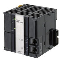
Omron NJ301-1 series User Manual (379 pages)
Machine Automation Controller NJ-series CPU Unit Hardware
Brand: Omron
|
Category: Controller
|
Size: 17 MB
Table of Contents
Advertisement

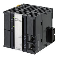
Omron NJ301-1 series User Manual (448 pages)
Machine Automation Controller
NJ/NX-series
CPU Unit
Brand: Omron
|
Category: Controller
|
Size: 13 MB
Table of Contents

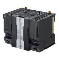
Omron NJ301-1 series User Manual (340 pages)
Machine Automation Controller CPU Unit Hardware
Brand: Omron
|
Category: Controller
|
Size: 8 MB
Table of Contents
Advertisement

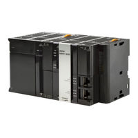
Omron NJ301-1 series User Manual (280 pages)
Machine Automation Controller, CPU Unit Built-in EtherCAT Port
Brand: Omron
|
Category: Controller
|
Size: 18 MB
Table of Contents
Omron NJ301-1 series User Manual (306 pages)
Machine Automation Controller
Brand: Omron
|
Category: Controller
|
Size: 7 MB
Table of Contents
Omron NJ301-1 series User Manual (256 pages)
NX-series; NJ-series
Machine Automation Controller
CPU Unit Built-in EtherCAT Port
Brand: Omron
|
Category: Controller
|
Size: 13 MB
Table of Contents
Omron NJ301-1 series Firmware Update Instruction (44 pages)
Machine Automation Controller
Brand: Omron
|
Category: Controller
|
Size: 0 MB
Table of Contents

Omron NJ301-1 series Instruction & Reference Manual (20 pages)
Machine Automation Controller
Brand: Omron
|
Category: Controller
|
Size: 0 MB
Advertisement