Omron sysmac NX Series User Manual
Machine automation controller system units
Hide thumbs
Also See for sysmac NX Series:
- User manual (986 pages) ,
- Owner's manual (570 pages) ,
- Hardware user manual (218 pages)
Table of Contents
Advertisement
Quick Links
Advertisement
Table of Contents
Troubleshooting

Subscribe to Our Youtube Channel
Related Manuals for Omron sysmac NX Series


Summary of Contents for Omron sysmac NX Series
- Page 1 Machine Automation Controller NX-series System Units User's Manual NX-PD1£££ NX-PF0£££ NX-PC0£££ NX-TBX01 Additional NX Unit Power Supply Units Additional I/O Power Supply Units I/O Power Supply Connection Units Shield Connection Units W523-E1-10...
- Page 2 • Every precaution has been taken in the preparation of this manual. Nevertheless, OMRON as- sumes no responsibility for errors or omissions. Neither is any liability assumed for damages resulting from the use of the information contained in this publication.
-
Page 3: Intended Audience
Introduction Introduction Thank you for purchasing an NX-series System Unit. This manual contains information that is necessary to use the NX-series System Unit. Please read this manual and make sure you understand the functionality and performance of the NX-series System Unit before you attempt to use it in a control system. -
Page 4: Relevant Manuals
Relevant Manuals Relevant Manuals To use the System Unit, you must refer to the manuals for all related products. Read all of the manuals that are relevant to your system configuration and application before you use the NX-series System Unit. System configuration Commu- (A) NX... - Page 5 Relevant Manuals System configuration Commu- (A) NX (D) Support (C) Slave nication Units Software (B) CPU Units Terminals Control Units Installation procedures ¡ Support Software connection procedures ¡ Performance calculations ¡ ¡ Making settings ¡ ¡ Troubleshooting Troubleshooting CPU Racks or Slave Ter- ¡...
- Page 6 Relevant Manuals NX-series System Units User's Manual (W523)
-
Page 7: Manual Structure
Manual Structure Manual Structure Page Structure The following page structure is used in this manual. Level 1 heading 4 Installation and Wiring Level 2 heading Mounting Units Level 3 heading Level 2 heading Gives the current Level 3 heading headings. 4-3-1 Connecting Controller Components The Units that make up an NJ-series Controller can be connected simply by pressing the Units together... -
Page 8: Special Information
Manual Structure Special Information Special information in this manual is classified as follows: Precautions for Safe Use Precautions on what to do and what not to do to ensure safe usage of the product. Precautions for Correct Use Precautions on what to do and what not to do to ensure proper operation and performance. Additional Information Additional information to read as required. - Page 9 Manual Structure • This user’s manual refers to the "built-in EtherCAT port on an NJ/NX-series Controller" or "built-in EtherCAT port on an NY-series Industrial PC" as simply a "built-in EtherCAT port". • This user's manual may omit manual names and manual numbers in places that refer to the user's manuals for CPU Units and Industrial PCs.
- Page 10 Manual Structure NX-series System Units User's Manual (W523)
-
Page 11: Sections In This Manual
Sections in this Manual Sections in this Manual Features and System Configuration Specifications Part Names and Functions Installation and Wiring Troubleshooting Inspection and Maintenance Appendices Index NX-series System Units User's Manual (W523) -
Page 12: Table Of Contents
CONTENTS CONTENTS Introduction ......................1 Intended Audience............................1 Applicable Products ............................1 Relevant Manuals..................... 2 Manual Structure...................... 5 Page Structure..............................5 Special Information ............................6 Precaution on Terminology ..........................6 Sections in this Manual ................... 9 Terms and Conditions Agreement................ 13 Warranty, Limitations of Liability ........................13 Application Considerations ..........................14 Disclaimers ..............................14 Statement of security responsibilities for assumed use cases and against threats........15... - Page 13 CONTENTS 1-2-2 System Configuration of Slave Terminals ...................1-5 1-2-3 System Configuration in the Case of a Communication Control Unit..........1-7 Model List ..........................1-10 1-3-1 Model Notation ..........................1-10 1-3-2 Additional NX Unit Power Supply Unit ..................1-11 1-3-3 Additional I/O Power Supply Unit ....................1-11 1-3-4 I/O Power Supply Connection Unit....................
- Page 14 CONTENTS Section 5 Troubleshooting How to Check for Errors......................5-2 Checking for Errors with the Indicators ................5-3 Checking for Errors and Troubleshooting on the Support Software........5-5 5-3-1 Checking for Errors from the Sysmac Studio ................5-5 5-3-2 Checking for Errors from Support Software Other Than the Sysmac Studio ......5-6 5-3-3 Event Codes and Corrections for Errors ..................5-6 5-3-4...
-
Page 15: Terms And Conditions Agreement
Omron’s exclusive warranty is that the Products will be free from defects in materials and work- manship for a period of twelve months from the date of sale by Omron (or such other period ex- pressed in writing by Omron). Omron disclaims all other warranties, express or implied. -
Page 16: Application Considerations
WAY CONNECTED WITH THE PRODUCTS, WHETHER SUCH CLAIM IS BASED IN CONTRACT, WARRANTY, NEGLIGENCE OR STRICT LIABILITY. Further, in no event shall liability of Omron Companies exceed the individual price of the Product on which liability is asserted. Application Considerations... -
Page 17: Statement Of Security Responsibilities For Assumed Use Cases And Against Threats
Product. Errors and Omissions Information presented by Omron Companies has been checked and is believed to be accurate; how- ever, no responsibility is assumed for clerical, typographical or proofreading errors or omissions. Statement of security responsibilities for assumed use cases and... -
Page 18: Safety Precautions
Safety Precautions Safety Precautions Definition of Precautionary Information The following notation is used in this manual to provide precautions required to ensure safe usage of the NX-series System Units. The safety precautions that are provided are extremely important to safety. Always read and heed the information provided in all safety precautions. -
Page 19: Warnings
Safety Precautions Warnings WARNING During Power Supply Do not touch the terminal section while power is ON. Electric shock may occur. Do not attempt to take any Unit apart. In particular, high-voltage parts are present in Units that supply power while power is supplied or immediately after power is turned OFF. - Page 20 Safety Precautions Voltage and Current Inputs Make sure that the voltages and currents that are input to the Units and slaves are within the specified ranges. Inputting voltages or currents that are outside of the specified ranges may cause acci- dents or fire.
-
Page 21: Cautions
Safety Precautions Cautions Caution Wiring When you connect a computer or other peripheral device to a Communications Coupler Unit that has a non-isolated DC power supply, either ground the 0-V side of the external power supply (i.e. Unit power supply) or do not ground it at all. If the peripheral devices are grounded incorrectly, the external power supply (i.e. -
Page 22: Precautions For Safe Use
Precautions for Safe Use Precautions for Safe Use Transporting • When transporting any Unit, use the special packing box for it. Also, do not subject the Unit to excessive vibration or shock during transportation. • Do not drop any Unit or subject it to abnormal vibration or shock. Doing so may result in Unit malfunction or burning. - Page 23 Precautions for Safe Use Restricted region (shaded portion) • For the installation orientations in the following figure, support the cables, e.g., with a duct, so that the End Plate on the bottom is not subjected to the weight of the cables. The weight of the cables may cause the bottom End Plate to slide downward so that the Slave Terminal is no longer secured to the DIN Track, which may result in malfunctions.
- Page 24 Precautions for Safe Use • If you use reed switches for the input contacts for AC Input Units, use switches with an allowable current of 1 A or greater. If the capacity of the reed switches is too low, inrush current may fuse the contacts.
- Page 25 Precautions for Safe Use • If you use fail-soft operation, write programming to determine whether Unit I/O data is valid. Without such programming, the user program cannot distinguish between Units for which I/O refreshing is continued and Units for which I/O refreshing is stopped. Turning OFF the Power Supply •...
- Page 26 Precautions for Safe Use Disposal • Dispose of the product according to local ordinances as they apply. NX-series System Units User's Manual (W523)
-
Page 27: Precautions For Correct Use
Precautions for Correct Use Precautions for Correct Use Storage, Mounting, and Wiring • Follow the instructions in this manual to correctly perform installation and wiring. • Do not operate or store the Units in the following locations. Doing so may result in malfunction, in operation stopping, or in burning. - Page 28 Precautions for Correct Use General Communications • Refer to the user’s manual for the Communications Coupler Unit for precautions for the correct use of communications with the connected Communications Coupler Unit. • Refer to the user’s manual for the Communication Control Unit for precautions for the correct use of communications with the connected Communication Control Unit.
-
Page 29: Regulations And Standards
Concepts EMC Directives OMRON devices that comply with EU Directives also conform to the related EMC standards so that they can be more easily built into other devices or the overall machine. The actual products have been checked for conformity to EMC standards.*1 Whether the products conform to the standards in the system used by the customer, however, must be checked by the customer. -
Page 30: Conformance To Ul And Csa Standards
If you use an NX-series product that complies with shipbuilding standards and the machinery or sys- tem in which you use the NX-series product must also comply with the standards, consult with your OMRON representative. Application conditions are defined according to the installation location. Appli- cation may not be possible for some installation locations. -
Page 31: Software Licenses And Copyrights
Regulations and Standards Software Licenses and Copyrights This product incorporates certain third party software. The license and copyright information associat- ed with this software is available at http://www.fa.omron.co.jp/nj_info_e/. NX-series System Units User's Manual (W523) -
Page 32: Unit Versions
Unit Versions Unit Versions This section describes the notation that is used for unit versions, the confirmation method for unit ver- sions, and the relationship between unit versions and Support Software versions. Unit Versions A “unit version” has been introduced to manage the Units in the NX Series according to differences in functionality accompanying Unit upgrades. - Page 33 Gives the unit version of the Unit. Lot number Gives the lot number of the Unit. DDMYY£: Lot number, £: Used by OMRON. “M” gives the month (1 to 9: January to September, X: October, Y: November, Z: December) The following information is provided in the notched area on the Unit.
-
Page 34: Unit Versions And Support Software Versions
Unit Versions Unit Versions and Support Software Versions The functions that are supported depend on the unit version of the Unit. The version of Support Soft- ware that supports the functions that were added for an upgrade is required to use those functions. Depending on the Unit to which the NX Unit is connected, refer to the following appendices for the functions that are supported by each unit version. -
Page 35: Related Manuals
Related Manuals Related Manuals The following table shows related manuals. Use these manuals for reference. Manual name Cat. No. Model numbers Application Description NX-series W523 NX-PD1£££ Learning how to The hardware and functions of the System Units use NX-series NX-series System Units are descri- NX-PF0£££... - Page 36 Related Manuals Manual name Cat. No. Model numbers Application Description NX-series W593 NX102-££££ Learning the basic An introduction to the entire NX102 NX102 CPU Unit specifications of system is provided along with the Hardware the NX102 CPU following information on the CPU User’s Manual Units, including in- Unit.
- Page 37 Related Manuals Manual name Cat. No. Model numbers Application Description NX-series Z395 NX-SL5£££ Learning how to Describes the hardware, setup Safety Control Unit / Com- NX-SI££££ use the NX-series methods, and functions of the NX- munication Control Unit NX-SO££££ Safety Control series Safety Control Units and User’s Manual Units and Com-...
-
Page 38: Terminology
Terminology Terminology Abbre- Term Description viation CPU Rack A Rack to which a CPU Unit or Communication Control Unit is mount- ed. For NX-series CPU Units to which NX Units can be connected, a CPU Rack has a CPU Unit with NX Units and an End Cover mounted to it. - Page 39 Terminology Abbre- Term Description viation Communication Control Unit An interface unit for CIP Safety communications between a Safety CPU Unit and a CIP Safety on EtherNet/IP device on a network. primary periodic task The task with the highest priority. Refer to the software user’s manual for the connected CPU Unit or In- dustrial PC for details.
-
Page 40: Revision History
Revision History Revision History A manual revision code appears as a suffix to the catalog number on the front and back covers of the manual. Cat. No. W523-E1-10 Revision code Revision Date Revised content code April 2013 Original production June 2013 Corrected mistakes. -
Page 41: Features And System Configuration
Features and System Configura- tion This section describes NX system configuration and System Unit types. Features and Types of System Units............1-2 1-1-1 System Unit Features..................1-2 1-1-2 System Unit Types ..................1-3 System Configuration ..................1-4 1-2-1 System Configuration in the Case of a CPU Unit..........1-4 1-2-2 System Configuration of Slave Terminals............ -
Page 42: Features And Types Of System Units
1 Features and System Configuration Features and Types of System Units This section describes features and types of System Units. 1-1-1 System Unit Features System Units are Units used to build the system for separating power supply systems or supplying power in the midstream in a CPU Rack or a Slave Terminal. -
Page 43: System Unit Types
1 Features and System Configuration *1. For whether NX Units can be connected to the CPU Unit or Communications Coupler Unit to be used, refer to the user’s manual for the CPU Unit or Communications Coupler Unit to be used. Simple I/O Wiring with a Screwless Clamping Terminal Block The terminal block is a screwless clamping terminal block. -
Page 44: System Configuration
1 Features and System Configuration System Configuration NX Unit NX-series System Units can be connected to the following Units. • NX-series CPU Unit • NX-series Communications Coupler Unit The following explains the system configuration for each NX Unit connection destination. 1-2-1 System Configuration in the Case of a CPU Unit The following figure shows a system configuration when a group of NX Units is connected to an NX-... -
Page 45: System Configuration Of Slave Terminals
1 Features and System Configuration Let- Item Description NX-series CPU Unit The Unit that serves as the center of control for a Machine Automation Con- troller. It executes tasks, refreshes I/O for other Units and slaves, etc. NX Units can be connected to an NX1P2 CPU Unit. The NX Units perform I/O processing with connected external devices. - Page 46 1 Features and System Configuration (E) Support Software (A) EtherCAT master NJ/NX-series CPU Unit, NY-series Industrial PC or master from another manufacturer .xml (F) ESI files EtherCAT port (G) Communications cable • EtherCAT Slave Terminal (E) Support Software Ethernet cables (B) NX-series Peripheral USB port EtherCAT Coupler Unit...
-
Page 47: System Configuration In The Case Of A Communication Control Unit
*2. For whether an NX Unit can be connected to the Communications Coupler Unit, refer to the version informa- tion in the user’s manual for the NX Unit. *3. The term Support Software indicates software that is provided by OMRON. If you connect to a master from another company, use the software tool corresponding to that master. - Page 48 1 Features and System Configuration (A) EtherNet/IP Unit EtherNet/IP port CPU Rack (I) Communications cable Ethernet cables (B) NX-series Communication Control Unit (H) Support Software NX-CSG320 (G) Network Configurator (D) End Cover Ethernet switch (C) NX Units • Safety CPU Unit •...
- Page 49 1 Features and System Configuration Let- Item Description • Safety CPU Unit NX Units This Unit serves as the center of control for the Safety Network Controller. It executes safety programs and CIP Safety communications. • Safety I/O Unit This Unit performs safety input or output processing. •...
-
Page 50: Model List
1 Features and System Configuration Model List 1-3-1 Model Notation The System Unit models are assigned based on the following rules. Model notation for the power supply-related Units (Additional NX Unit Power Supply Unit, Additional I/O Power Supply Unit and I/O Power Supply Connection Unit) differs from that of System Units other than power supply-related Units. -
Page 51: Additional Nx Unit Power Supply Unit
1 Features and System Configuration 1-3-2 Additional NX Unit Power Supply Unit This section shows a list of Additional NX Unit Power Supply Units. Refer to A-1-2 Additional NX Unit Power Supply Unit on page A-3 for details. Screwless Clamping Terminal Block, 12 mm Width Rated power supply Model NX Unit power supply capacity... - Page 52 1 Features and System Configuration Screwless Clamping Terminal Block, 12 mm Width Model Number of shield terminals Reference NX-TBX01 14 terminals page A-21 (The following two terminals are functional ground terminals.) 1-12 NX-series System Units User's Manual (W523)
-
Page 53: Support Software
1 Features and System Configuration Support Software The Support Software that is used depends on the system configuration. • Support Software for a System Configured with a CPU Unit If your system is configured by connecting an NX Unit to a CPU Unit, the Sysmac Studio is used as the Support Software. - Page 54 1 Features and System Configuration 1-14 NX-series System Units User's Manual (W523)
-
Page 55: Specifications
Specifications This section describes the general specifications and individual specifications of Sys- tem Units. General Specifications .................. 2-2 Individual Specifications ................2-3 NX-series System Units User's Manual (W523) -
Page 56: General Specifications
KC (KC Registration), NK, and LR Note 1. The specifications of insulation resistance and dielectric strength vary with NX Unit Models. Note 2. Refer to the OMRON website (www.ia.omron.com) or ask your OMRON representative for the most re- cent applicable standards for each model. -
Page 57: Individual Specifications
2 Specifications Individual Specifications Refer to A-1 Data Sheet on page A-2 for the specifications of individual System Units. NX-series System Units User's Manual (W523) - Page 58 2 Specifications NX-series System Units User's Manual (W523)
- Page 59 Part Names and Functions This section describes the names and functions of the System Unit parts. Names of Power Supply-related Unit Parts ..........3-2 3-1-1 Screwless Clamping Terminal Block Type............3-2 3-1-2 Indicators......................3-6 Names of Shield Connection Unit Parts............3-9 3-2-1 Screwless Clamping Terminal Block Type............
-
Page 60: Names Of Power Supply-Related Unit Parts
3 Part Names and Functions Names of Power Supply-related Unit Parts This section describes the names and functions of power supply-related Unit parts (Additional NX Unit Power Supply Unit, Additional I/O Power Supply Unit, and I/O Power Supply Connection Unit). 3-1-1 Screwless Clamping Terminal Block Type NX Units (12 mm Width) - Page 61 3 Part Names and Functions Terminal Blocks There are two models of screwless clamping terminal blocks: NX-TB£££2 and NX-TB£££1. Each model has three types of terminal blocks: 8-terminal type, 12-terminal type, and 16-terminal type. Use the 8-terminal type and the 16-terminal type for the power supply-related Units. ...
- Page 62 3 Part Names and Functions Let- Name Function Terminal number indi- Terminal numbers for which A and B indicate the column, and 1 to 8 indicate cations the line are displayed. The terminal number is a combination of column and line, i.e. A1 to A8 and B1 to B8.
- Page 63 3 Part Names and Functions Precautions for Correct Use You can mount either NX-TB£££1 or NX-TB£££2 Terminal Blocks to the Units that the cur- rent capacity specification of the terminals is 4 A or less. However, even if you mount the NX-TB£££2 Terminal Block, the current specification does not change because the current capacity specification of the terminals on the Units is 4 A or less.
-
Page 64: Indicators
3 Part Names and Functions 3-1-2 Indicators The Additional NX Unit Power Supply Unit, Additional I/O Power Supply Unit, and I/O Power Supply Connection Unit have indicators that show the current operating status of the NX Unit. The following indicator patterns are available depending on the Unit types. The appearance of the indicators has been changed for models released in or before September 2018 with lot numbers that represent the date of or after September 20, 2018. - Page 65 3 Part Names and Functions Color Status Description Green The Unit is operating normally. The Unit is ready for I/O refreshing. • Flashing (at 2-s in- Initializing • tervals) Restarting is in progress for the Unit. • Downloading A hardware failure, WDT error, or other fatal error that is common to all I/O Units occurred.
- Page 66 3 Part Names and Functions Color Status Description Green The I/O power is supplied. Not lit The I/O power is not supplied. Appearance Change of the Indicators The appearance of the indicators has been changed for models released in or before September 2018 with lot numbers that represent the date of or after September 20, 2018.
-
Page 67: Names Of Shield Connection Unit Parts
3 Part Names and Functions Names of Shield Connection Unit Parts This section describes the names and functions of the Shield Connection Unit parts. 3-2-1 Screwless Clamping Terminal Block Type NX Units (12 mm Width) Letter Name Function Marker attachment loca- The locations where markers are attached. - Page 68 3 Part Names and Functions Terminal Blocks There are two models of screwless clamping terminal blocks: NX-TB£££2 and NX-TB£££1. Each model has three types of terminal blocks: 8-terminal type, 12-terminal type, and 16-terminal type. Use the 16-terminal type for the Shield Connection Unit. ...
- Page 69 3 Part Names and Functions Let- Name Function Terminal number indi- Terminal numbers for which A and B indicate the column, and 1 to 8 indicate cations the line are displayed. The terminal number is a combination of column and line, i.e. A1 to A8 and B1 to B8.
-
Page 70: Indicators
3 Part Names and Functions 3-2-2 Indicators A Shield Connection Unit has indicators that show the current operating status of the NX Unit. The appearance of the indicators has been changed for models released in or before September 2018 with lot numbers that represent the date of or after September 20, 2018. In this manual, those models are shown with the indicators after the change. - Page 71 3 Part Names and Functions Color Status Description Green The Unit is operating normally. The Unit is ready for I/O refreshing. • Flashing (at 2-s in- Initializing • tervals) Restarting is in progress for the Unit. • Downloading A hardware failure, WDT error, or other fatal error that is common to all I/O Units occurred.
- Page 72 3 Part Names and Functions 3-14 NX-series System Units User's Manual (W523)
-
Page 73: Installation And Wiring
Installation and Wiring This section describes how to install the NX Units, the types of power supplies used in the CPU Rack or Slave Terminal, their wiring methods, and how to wire the NX Units. Installing NX Units..................4-2 4-1-1 Installing NX Units ................... -
Page 74: Installing Nx Units
4 Installation and Wiring Installing NX Units This section describes how to install NX Units. Refer to the user’s manual for the CPU Unit, Communications Coupler Unit, or Communication Control Unit to which NX Units are connected for information on preparations of installation and installation in a control panel. - Page 75 4 Installation and Wiring Precautions for Safe Use • Always turn OFF the power supply before installing the Unit. If the power supply is not OFF, the Unit may malfunction or may be damaged. • Do not apply labels or tape to the Unit. When the Unit is installed or removed, adhesive or scraps may adhere to the pins in the NX bus connector, which may result in malfunctions.
- Page 76 4 Installation and Wiring Unit hookup guides Unit hookup guides Slide the NX Unit in on the hookup guides. Press the NX Unit with a certain amount of force against the DIN Track until you hear the DIN Track mounting hook lock into place. When you mount the NX Unit, it is not necessary to unlock the DIN Track mounting hook on the NX Unit.
-
Page 77: Attaching Markers
Attaching Markers You can attach markers to the NX Units to identify them. The plastic markers made by OMRON are installed for the factory setting. The ID information can be written on them. Commercially available markers can also be installed. -
Page 78: Removing Nx Units
UC1-TMF8 DEK 5/8 Special marker printer UM EN BLUEMARK X1 PrintJet PRO The markers made by OMRON cannot be printed on with commercially available special printers. 4-1-3 Removing NX Units This section describes how to remove NX Units. Precautions for Safe Use Always turn OFF the Unit power supply and I/O power supply before you remove the NX Unit. -
Page 79: Installation Orientation
4 Installation and Wiring Protrusion for removing the Unit Protrusion for removing the Unit Precautions for Correct Use • When you need to remove an NX Unit, always remove more than one NX Unit at a time, in- cluding the Unit you need to remove. It is sometimes very difficult to remove only one NX Unit by itself. - Page 80 4 Installation and Wiring Installation Orientation on Slave Terminals The Slave Terminal can be installed in any of the following six orientations. (A) is the upright installation orientation and (B) to (F) are installation orientations other than upright. Upper Lower However, there are restrictions on the installation orientation and restrictions to the specifications that can result from the Communications Coupler Units and NX Units that are used.
-
Page 81: Wiring The Power Supply To The Cpu Unit
4 Installation and Wiring Wiring the Power Supply to the CPU Unit This section describes the methods of power supplying and wiring with NX Unit in a CPU Rack when connecting NX Unit with NX-series CPU Unit. 4-2-1 Power Supply Types There are the following two types of power supplies that supply power to the CPU Rack of the CPU Unit. - Page 82 4 Installation and Wiring Power supply Description name NX Unit power This power is supplied to the NX Units through the NX bus connectors by connecting a Unit supply power supply to the Unit power supply terminals on the CPU Unit or Additional NX Unit Power Supply Units.
- Page 83 4 Installation and Wiring The following are wiring diagrams (examples) for each power supply. (Example) DC Input Unit 24 VDC 24 VDC I/O power Unit power supply supply Additional I/O Additional NX Unit Two-wire Power Supply Unit Power Supply Unit Input Unit sensor Three-wire...
-
Page 84: Power Supply-Related Units And Wiring Methods
The CPU Unit supplies the NX Unit power to the NX Units in the CPU Rack. There are the following types of NX-series power supply-related Units other than CPU Unit. Refer to NX-series catalogs or OMRON websites, or ask your OMRON representative for information on the most recent lineup of NX Units. - Page 85 4 Installation and Wiring Unit name Function Additional I/O Power This NX Unit provides additional I/O power supply. Supply Unit This Unit is used when the I/O power supply for the NX Unit connected to the CPU Unit is supplied through the NX bus. Additionally use this NX Unit in the following cases.
- Page 86 4 Installation and Wiring Unit name Function I/O Power Supply Con- This NX Unit is used when there are not enough I/O power supply terminals for the nection Unit connected external devices that are connected to NX Units such as Digital I/O Units and Analog I/O Units.
-
Page 87: Wiring The Power Supply To The Slave Terminal
4 Installation and Wiring Wiring the Power Supply to the Slave Terminal This section describes how to supply power to the Slave Terminal and wiring. 4-3-1 Power Supply Types There are the following two types of power supplies that supply power to the Slave Terminal. Power supply Description name... - Page 88 4 Installation and Wiring The following are wiring diagrams (examples) for each power supply. (Example) DC Input Unit 24 VDC I/O 24 VDC Unit power supply power supply Additional I/O Additional DC Input Unit NX Unit Power Power Supply Unit Two-wire Supply Unit sensor...
-
Page 89: Power Supply-Related Units And Wiring Methods
Slave Terminal. There are the following types of NX-series power supply-related Units other than Communications Coupler Unit. Refer to NX-series catalogs or OMRON websites, or ask your OMRON representative for information on the most recent lineup of NX Units. Unit name... - Page 90 4 Installation and Wiring Unit name Function Additional I/O Power This NX Unit provides additional I/O power supply. Supply Unit Use this NX Unit in the following cases. a. When the I/O power supply capacity is insufficient • When the total current consumption for the I/O power supply exceeds the maxi- mum current of I/O power supply of the Communications Coupler Unit •...
- Page 91 4 Installation and Wiring Unit name Function I/O Power Supply Con- This NX Unit is used when there are not enough I/O power supply terminals for the nection Unit connected external devices that are connected to NX Units such as Digital I/O Units and Analog I/O Units.
-
Page 92: Wiring The Power Supply To The Communication Control Unit
4 Installation and Wiring Wiring the Power Supply to the Com- munication Control Unit This section describes the methods of power supplying and wiring with NX Unit in a CPU Rack when connecting NX Unit with NX-series Communication Control Unit. 4-4-1 Power Supply Types There are the following two types of power supplies that supply power to the CPU Rack of the Com-... - Page 93 4 Installation and Wiring Power supply Description name I/O power sup- This power is supplied by one of the following two methods. • Supply from the NX bus This power is supplied through the NX bus connectors by connecting an I/O power supply to the I/O power supply terminals on the Communication Control Unit or Additional I/O Pow- er Supply Unit.
-
Page 94: Power Supply-Related Units And Wiring Methods
There are the following types of NX-series power supply-related Units other than Communication Con- trol Unit. Refer to NX-series catalogs or OMRON websites, or ask your OMRON representative for information on the most recent lineup of NX Units. Unit name... - Page 95 4 Installation and Wiring Unit name Function Additional I/O Power This NX Unit provides additional I/O power supply. Supply Unit Use this NX Unit in the following cases. a. When the I/O power supply capacity is insufficient • When the total current consumption for the I/O power supply exceeds the maxi- mum current of I/O power supply of the Communication Control Unit •...
- Page 96 4 Installation and Wiring Unit name Function I/O Power Supply Con- This NX Unit is used when there are not enough I/O power supply terminals for the nection Unit connected external devices that are connected to NX Units such as Digital I/O Units and Analog I/O Units.
-
Page 97: Wiring Of Grounding
4 Installation and Wiring Wiring of Grounding This section describes how to ground the CPU Rack and the Slave Terminal. Units with Functional Ground Terminals in CPU Rack of CPU Unit Some of the Units in a CPU Rack of the NX-series CPU Unit have the following functional ground ter- minals. - Page 98 4 Installation and Wiring Additional Information A Shield Connection Unit is used to connect the shield when connecting to external input devi- ces. You can ground more than one shield to the same ground pole to reduce the amount of wiring work for grounding.
-
Page 99: Wiring The Additional Power Supply Units
4 Installation and Wiring Wiring the Additional Power Supply Units This section describes how to wire the terminals on the Additional Power Supply Units. WARNING Make sure that the voltages and currents that are input to the Units and slaves are within the specified ranges. -
Page 100: Wiring The Additional Nx Unit Power Supply Unit
4 Installation and Wiring 4-6-1 Wiring the Additional NX Unit Power Supply Unit This section describes how to wire Additional NX Unit Power Supply Unit. Wiring Terminals • Unit power supply terminals • Functional ground terminals Wiring Examples The Unit power supply is connected to the Unit power supply terminal (UV/UG). You can use the unwired terminals of the Unit power supply terminals for through-wiring to the Unit power supply terminals on an Additional NX Unit Power Supply Unit, other CPU Units to which NX Units can be connected, other Communications Coupler Units or another Communication Control Unit. - Page 101 • Has an output voltage that falls within the power supply voltage range for the Unit power supply. We recommend the following power supply. Recommended power supply in a CPU Rack: Model S8VK-S series (Omron) Recommended power supply in a Slave Terminal: Model S8VK-S series or Model S8JX series (Om-...
- Page 102 4 Installation and Wiring Additional NX Unit Power CPU Unit block Supply Unit block NX Unit connected NX Unit connected to the Additional to the CPU Unit NX Unit Power Supply Unit NX-series CPU Unit NX Unit power supply NX Unit power supply Internal power supply circuit Unit power supply terminals...
- Page 103 4 Installation and Wiring Communications Coupler Additional NX Unit Power Unit block Supply Unit block NX Unit connected to the Communications NX Unit connected to the Additional Commu- Coupler Unit NX Unit Power Supply Unit nications Coupler Unit power supply Unit terminals NX Unit power supply...
-
Page 104: Wiring The Additional I/O Power Supply Unit
4 Installation and Wiring The following shows the Unit that supplies NX Unit power and its supplying range. For example, the CPU Rack in the following diagram is configured with two blocks: the Communication Control Unit block and the Additional NX Unit Power Supply Unit block. Communication Control Unit Additional NX Unit Power Supply block... - Page 105 4 Installation and Wiring NPN Type (NX-ID5342) Two-wire sensor Additional I/O Digital Input Unit (e.g. limit switch) Power Supply Unit (NPN type) NX-PF0730 NX-ID5342 Brown (White) Blue (Black) 24 VDC I/O power supply IOG IOG Three-wire sensor with NPN output (photoelectric sensor or proximity sensor) Black (White)
- Page 106 *1. Use an output voltage that is appropriate for the I/O circuits of the NX Units and the connected external devices. We recommend the following power supply. Recommended power supply in a CPU Rack: Model S8VK-S series (Omron) Recommended power supply in a Slave Terminal: Model S8VK-S series or Model S8JX series (Omron) ...
- Page 107 4 Installation and Wiring Connecting destination of Model of Additional I/O Power Additional I/O Power Sup- Peak value Pulse width Supply Unit ply Unit NX1P2 CPU Unit NX-PF0730 20 A NX-PF0630 • NX-PF0730 50 A NX502 CPU Unit • NX102 CPU Unit NX-PF0630 20 A •...
- Page 108 4 Installation and Wiring Precautions for Correct Use Select an I/O power supply with sufficient capacity by considering the inrush current when the power is turned ON. Sometimes, the I/O power supply may not be turned ON caused by inrush current when the power is turned ON.
- Page 109 4 Installation and Wiring NX-PF0730 Current Con- = (Current consumption from I/O power supply) sumption = 10 mA NX-ID3317 Current Con- = (Current consumption from I/O power supply) + (Input current × Num- sumption ber of inputs used) + (Total current consumption of connected input devices) = 0 mA + (6 mA x 4 points) + (50 mA x 4 points) = 224 mA NX-OD3121 Current Con-...
-
Page 110: Protective Devices
4 Installation and Wiring 4-6-3 Protective Devices This section describes the protective devices to protect against short circuits and overcurrents of ex- ternal circuits. Overcurrent means the current that flows when an excessive load is connected and one of the follow- ing ratings is exceeded. - Page 111 4 Installation and Wiring • CPU Unit Hardware User’s Manual • User’s manual for the Communications Coupler Unit • User’s manual for the Communication Control Unit Refer to Required Power Supply Capacity on page 4-34 for information on the inrush current that occurs when external devices connected to an Additional I/O Power Supply Unit are turned ON or OFF, which is one of the items to consider when you select protective devices.
-
Page 112: Wiring The I/O Power Supply Connection Unit
4 Installation and Wiring Wiring the I/O Power Supply Connec- tion Unit The I/O Power Supply Connection Unit is used as additional I/O power supply terminals when there are not enough I/O power supply terminals in which it is connected to the connected external devices. This section describes how to wire the I/O Power Supply Connection Unit. - Page 113 4 Installation and Wiring PNP type (NX-ID5442) I/O Power Supply Digital Input Unit Two-wire sensor Connection Unit (PNP type) NX-PC0030 (e.g. limit switch) NX-ID5442 (8 each of IOV/IOG Brown (White) terminals) Blue (Black) Three-wire sensor with PNP output (photoelectric sensor or proximity sensor) Black (White) Brown (Red)
- Page 114 4 Installation and Wiring PNP type (NX-OD5256) I/O Power Supply Digital Output Unit Connection Unit (PNP type) NX-PC0010 NX-OD5256 (16 IOG terminals) Solenoid, valve, etc. Solenoid, valve, etc. Wiring Example 3 When the I/O Power Supply Connection Unit (NX-PC0020 or NX-PC0010) is connected to an Ana- log Input Unit (8 inputs, single-ended inputs) For voltage 8 inputs (NX-AD4603) I/O Power Supply...
- Page 115 4 Installation and Wiring For current 8 inputs (NX-AD4203) I/O Power Supply Analog Input Unit Connection Unit (Single-ended) NX-PC0010 NX-AD4203 (16 IOG terminals) Current input + 24 VDC (sensor power supply +) 0 V (sensor power supply –) Three-wire sensor Current input + 24 VDC (sensor power supply +) Two-wire sensor...
-
Page 116: Wiring The Shield Connection Unit
4 Installation and Wiring Wiring the Shield Connection Unit The Shield Connection Unit is used when there are not enough terminals to connect the shield for the connection of external devices. This section describes how to wire the Shield Connection Unit. Wiring Terminals •... -
Page 117: Wiring The Terminals
4 Installation and Wiring Wiring the Terminals This section describes how to wire the terminals on the System Units. WARNING Make sure that the voltages and currents that are input to the Units and slaves are within the specified ranges. Inputting voltages or currents that are outside of the speci- fied ranges may cause accidents or fire. - Page 118 4 Installation and Wiring 1.6 mm max. (except ground terminals) 2.0 mm max. (ground terminals) 2.4 mm max. (except ground terminals) 2.7 mm max. (ground terminals) Using Ferrules If you use ferrules, attach the twisted wires to them. Observe the application instructions for your ferrules for the wire stripping length when attaching ferrules.
- Page 119 4 Installation and Wiring When you use any ferrules other than those in the above table, crimp them to the twisted wires so that the following processed dimensions are achieved. 8 to 10 mm 1.6 mm max. (except ground terminals) 2.0 mm max.
- Page 120 4 Installation and Wiring Precautions for Correct Use • Use cables with suitable wire sizes for the carrying current. There are also restrictions on the current due to the ambient temperature. Refer to the manuals for the cables and use the ca- bles correctly for the operating environment.
- Page 121 4 Installation and Wiring Model Manufacturer SZF 0-0,4X2,5 Phoenix Contact Connecting Ferrules Insert the ferrule straight into the terminal hole. You do not need to insert a flat-blade screwdriver into the release hole. Ferrule After you make a connection, make sure that the ferrule is securely connected to the terminal block.
- Page 122 4 Installation and Wiring Twisted wire or Solid wire Remove the flat-blade screwdriver from the release hole. After you make a connection, lightly pull the twisted wire or the solid wire to make sure that the wire is securely connected to the terminal block. Precautions for Safe Use •...
- Page 123 4 Installation and Wiring Securing Wires It is necessary to secure wires to the screwless clamping terminal block depending on the wire types that are used or the current flows on the wires. The following table gives the necessity for securing wires. Terminals Wire type Twisted wires...
- Page 124 4 Installation and Wiring Bundle the wires with a cable tie and secure them to the screwless clamping terminal block. Secure wires within the range of 30 mm from the screwless clamping terminal block. 30 mm Removing Wires Use the following procedure to remove the wires from the terminal block. The removal method is the same for ferrules, twisted wires, and solid wires.
- Page 125 4 Installation and Wiring Flat-blade screwdriver 10° to 15° Insert the flat-blade screwdriver into the release hole and remove the wire from the terminal hole. Wire Remove the flat-blade screwdriver from the release hole. 4-53 NX-series System Units User's Manual (W523)
- Page 126 4 Installation and Wiring Precautions for Safe Use • Do not press the flat-blade screwdriver straight into the release holes on a screwless clamp- ing terminal block. Doing so may damage the terminal block. • When you insert a flat-blade screwdriver into a release hole on a screwless clamping terminal block, press it down with a force of 30N or less.
-
Page 127: Preventing Incorrect Attachment Of Terminal Blocks
4 Installation and Wiring Mount the terminal block hook that is applicable to each Unit model on the guide at the bottom of the NX Unit, lift up the terminal block, and press in on the top of the terminal block until you hear it engage. - Page 128 4 Installation and Wiring Unit Terminal block Cannot be attached. Types of Coding Pins There are two types of Coding Pins, both with their own unique shape: one for terminal blocks and one for Units. Three pins come with each runner. For terminal block For Unit Runners...
- Page 129 4 Installation and Wiring Terminal block Unit Holes used by Holes used by OMRON OMRON Holes for incorrect Holes for incorrect attachment prevention attachment prevention (pin locations) (pin locations) ○: Pin inserted Pin locations for Pin locations for Unit terminal block Pattern No.1...
- Page 130 • The holes not designated by the numbers 1 through 6 in the above figure are used by OM- RON. If you insert any Coding Pins into the holes reserved for use by OMRON, you will not be able to mount the terminal block to the Unit.
- Page 131 4 Installation and Wiring Unit 4-59 NX-series System Units User's Manual (W523)
- Page 132 4 Installation and Wiring 4-60 NX-series System Units User's Manual (W523)
-
Page 133: Troubleshooting
Troubleshooting This section describes the error information and corrections for errors that can occur when the System Units are used. How to Check for Errors ................5-2 Checking for Errors with the Indicators............5-3 Checking for Errors and Troubleshooting on the Support Software ..5-5 5-3-1 Checking for Errors from the Sysmac Studio .......... -
Page 134: How To Check For Errors
5 Troubleshooting How to Check for Errors Use one of the following error checking methods. • Checking the indicators • Troubleshooting with the Support Software Refer to the troubleshooting manual for the CPU Unit, or the user’s manual for the Communications Coupler Unit or Communication Control Unit that the NX Units are connected to for details on trouble- shooting with the Support Software. -
Page 135: Checking For Errors With The Indicators
5 Troubleshooting Checking for Errors with the Indica- tors You can use the indicators on the System Units to check the status of System Units and level of er- rors. This section describes the meanings of errors that the indicator shows and the troubleshooting proce- dures for them. - Page 136 5 Troubleshooting Additional NX Unit Power Supply Unit UNIT PWR indica- Cause Correction Green The Unit power supply is supplied. --- (This is the normal status.) Not Lit The Unit power supply is not sup- Check the following items and supply the Unit plied.
-
Page 137: Checking For Errors And Troubleshooting On The Support Software
5 Troubleshooting Checking for Errors and Trouble- shooting on the Support Software Error management on the NX Series is based on the methods used for the NJ/NX/NY-series Control- lers. This allows you to use the Support Software to check the meanings of errors and troubleshooting pro- cedures. -
Page 138: Checking For Errors From Support Software Other Than The Sysmac Studio
5 Troubleshooting Log of Past Errors Open the Sysmac Studio's Controller Event Log Tab Page to check the times, levels, sources, source details, event names, event codes, details, attached information 1 to 4, and corrections for previous errors. Additional Information Number of Logs of Past Errors Event logs in the System Units are stored in the CPU Unit, Communications Coupler Unit, or Communication Control Unit to which they are connected. -
Page 139: Meaning Of Error
5 Troubleshooting Level Event Refer- Event code Meaning Assumed cause name ence • 00200000 hex Non-vola- An error occurred Non-volatile memory fail- ¡ page tile Memo- in non-volatile ry Hard- memory. ware Error • 90400000 hex Event Log The event log was The event log was cleared ¡... - Page 140 • Starts: Execution of the user program starts. *5. “System information” indicates internal system information that is used by OMRON. *6. Refer to the appendices of the troubleshooting manual for the connected CPU Unit or Industrial PC for the applicable range of the HMI Troubleshooter.
- Page 141 5 Troubleshooting Event name Non-volatile Memory Hardware Error Event code 00200000 hex Meaning An error occurred in non-volatile memory. Source Depends on where the Support Source details NX Unit Detection tim- When power is Software is connected and the turned ON to system configuration.
- Page 142 5 Troubleshooting Event name Event Log Cleared Event code 90400000 hex Meaning The event log was cleared. Source Depends on where the Support Source details NX Unit Detection tim- When com- Software is connected and the manded from system configuration. user Error attrib- Level...
-
Page 143: Resetting Errors
5 Troubleshooting Resetting Errors Refer to the troubleshooting manual for the connected CPU Unit, or the user’s manual for the Commu- nications Coupler Unit or Communication Control Unit for information on how to reset errors. 5-11 NX-series System Units User's Manual (W523) -
Page 144: Troubles Specific To Each Type Of Nx Units
5 Troubleshooting Troubles Specific to Each Type of NX Units 5-5-1 Additional NX Unit Power Supply Unit Problem Assumed cause Correction The UNIT PWR indi- The Unit power is not supplied. Check that the Unit power is supplied. cator is not lit. The Unit power supply voltage is out- Set the Unit power supply voltage within the side the specified range. -
Page 145: Troubleshooting Flowchart
5 Troubleshooting Troubleshooting Flowchart Refer to the troubleshooting manual for the connected CPU Unit, or the user’s manual for the Commu- nications Coupler Unit or Communication Control Unit for the standard flow for troubleshooting errors. 5-13 NX-series System Units User's Manual (W523) - Page 146 5 Troubleshooting 5-14 NX-series System Units User's Manual (W523)
- Page 147 Inspection and Maintenance This section describes how to clean, inspect, and maintain the system. Cleaning and Inspection................6-2 6-1-1 Cleaning ......................6-2 6-1-2 Periodic Inspections ..................6-2 Maintenance Procedures................6-5 NX-series System Units User's Manual (W523)
-
Page 148: Cleaning And Inspection
6 Inspection and Maintenance Cleaning and Inspection This section describes daily maintenance and the cleaning and inspection methods. Inspect the System Units daily or periodically in order to keep it in optimal operating condition. 6-1-1 Cleaning Clean the System Units regularly as described below in order to keep it in optimal operating condition. •... - Page 149 6 Inspection and Maintenance Inspec- Inspection details Criteria Correction tion item Ambient Is the ambient operating 0 to 55°C Use a thermometer to check the environ- temperature within stand- temperature and ensure that the ment ards? ambient operating temperature re- mains within the allowed range of 0 to 55°C.
- Page 150 6 Inspection and Maintenance • Voltage tester or digital voltmeter • Industrial alcohol and pure cotton cloth Tools Required Occasionally • Oscilloscope • Thermometer and hygrometer NX-series System Units User's Manual (W523)
-
Page 151: Maintenance Procedures
6 Inspection and Maintenance Maintenance Procedures When you replace a System Unit, follow the procedure in the user’s manual for the connected CPU Unit, Communications Coupler Unit, or Communication Control Unit. NX-series System Units User's Manual (W523) - Page 152 6 Inspection and Maintenance NX-series System Units User's Manual (W523)
-
Page 153: Appendices
Appendices This section describes the data sheets of the System Units and their dimensions. Data Sheet...................... A-2 A-1-1 Model List ......................A-2 A-1-2 Additional NX Unit Power Supply Unit............. A-3 A-1-3 Additional I/O Power Supply Unit ..............A-7 A-1-4 I/O Power Supply Connection Unit..............A-12 A-1-5 Shield Connection Unit.................. -
Page 154: A-1 Data Sheet
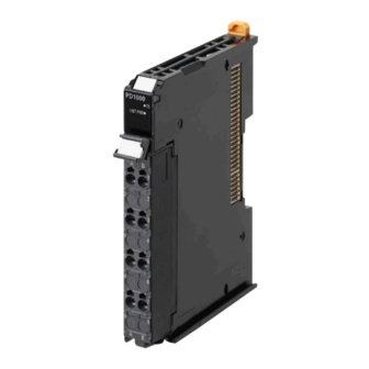
Appendices A-1 Data Sheet The specifications of individual System Units are shown below. A-1-1 Model List Additional NX Unit Power Supply Unit Rated power supply Model NX Unit power supply capacity Reference voltage NX-PD1000 24 VDC 10 W max. page A-5 Additional I/O Power Supply Unit Rated power supply Maximum current of I/O power... -
Page 155: A-1-2 Additional Nx Unit Power Supply Unit
Appendices A-1-2 Additional NX Unit Power Supply Unit Description of Items on the Data Sheet of the Additional NX Unit Power Supply Unit The meanings of the items on the data sheet of the Additional NX Unit Power Supply Unit are ex- plained in the table below. - Page 156 Appendices Item Description Terminal connection di- A diagram of the connection between the Unit and connected external devices. agram When an I/O Power Supply Connection Unit or a Shield Connection Unit is required to be connected to the connected external devices, the description for such is in- cluded.
- Page 157 Appendices Additional NX Unit Power Supply Unit (Screwless Clamping Termi- nal Block, 12 mm Width) Unit name Additional NX Unit Power Supply Unit Model NX-PD1000 External connection ter- Screwless clamping terminal block (8 terminals) minals Power supply voltage 24 VDC (20.4 to 28.8 VDC) NX Unit power supply 10 W max.
- Page 158 Appendices Installation orientation Installation orientation: • and restrictions Connected to a CPU Unit or Communication Control Unit Possible in upright installation. • Connected to a Communications Coupler Unit Possible in 6 orientations. Restrictions: As shown in the following. • For upright installation For 10 W output, 40°C Output power (W) For 8.5 W output, 55°C...
-
Page 159: A-1-3 Additional I/O Power Supply Unit
Appendices *2. The NC terminals are not connected to the internal circuits. A-1-3 Additional I/O Power Supply Unit Description of Items on the Data Sheet of the Additional I/O Power Supply Unit The meanings of the items on the data sheet of the Additional I/O Power Supply Unit are explained in the table below. - Page 160 Appendices Item Description Overload/low voltage The function of the Unit to detect an overload and low voltage in the I/O power sup- detection ply. Protective function The protective function that the Unit has. NX-series System Units User's Manual (W523)
- Page 161 Appendices Additional I/O Power Supply Units (Screwless Clamping Terminal Block, 12 mm Width) Unit name Additional I/O Power Supply Unit Model NX-PF0630 External connection ter- Screwless clamping terminal block (8 terminals) minals Power supply voltage 5 to 24 VDC (4.5 to 28.8 VDC) Maximum current of I/O power supply Current capacity of I/O...
- Page 162 Appendices Terminal connection di- Additional I/O DC Input Unit agram Power Supply Unit NX-PD0630 Two-wire type 24 VDC Three-wire type Overload/low voltage Not supported. detection Protective function Not supported. Use a voltage that is appropriate for the I/O circuits of the NX Units and the connected external devices. A-10 NX-series System Units User's Manual (W523)
- Page 163 Appendices Unit name Additional I/O Power Supply Unit Model NX-PF0730 External connection ter- Screwless clamping terminal block (8 terminals) minals Power supply voltage 5 to 24 VDC (4.5 to 28.8 VDC) Maximum current of I/O 10 A power supply Current capacity of I/O •...
-
Page 164: A-1-4 I/O Power Supply Connection Unit
Appendices Terminal connection di- Additional I/O DC Input Unit agram Power Supply Unit NX-PF0730 Two-wire type 24 VDC Three-wire type Overload/low voltage Not supported. detection Protective function Not supported. Use a voltage that is appropriate for the I/O circuits of the NX Units and the connected external devices. When an Additional I/O Power Supply Unit is connected to the CPU Rack of a CPU Unit, the maximum I/O power sup- ply current value may be smaller than that of the Additional I/O Power Supply Unit. - Page 165 Appendices Item Description NX Unit power con- The power consumption of the NX Unit power supply of the Unit. The power con- sumption sumption of the Unit connected to each of the following Units is separately given. If some of the following Units can not be connected to the Unit, relevant information is omitted.
- Page 166 Appendices I/O Power Supply Connection Unit (Screwless Clamping Terminal Block, 12 mm Width) IOV Terminal Type Unit name I/O Power Supply Connection Unit Model NX-PC0020 External connection ter- Screwless clamping terminal block (16 terminals) minals Number of I/O power IOV: 16 terminals supply terminals Current capacity of I/O...
- Page 167 Appendices Terminal connection di- agram I/O Power Supply DC Input Unit Connection Unit Three-wire type NX-PC0020 Transistor Output Unit A-15 NX-series System Units User's Manual (W523)
- Page 168 Appendices IOG Terminal Type Unit name I/O Power Supply Connection Unit Model NX-PC0010 External connection ter- Screwless clamping terminal block (16 terminals) minals Number of I/O power IOG: 16 terminals supply terminals Current capacity of I/O 4 A/terminal max. power supply terminal Dimensions 12 (W) ×...
- Page 169 Appendices Terminal connection di- agram I/O Power Supply DC Input Unit Connection Unit Three-wire type NX-PC0010 Transistor Output Unit A-17 NX-series System Units User's Manual (W523)
- Page 170 Appendices IOV/IOG Terminal Type Unit name I/O Power Supply Connection Unit Model NX-PC0030 External connection ter- Screwless clamping terminal block (16 terminals) minals Number of I/O power IOV: 8 terminals supply terminals IOG: 8 terminals Current capacity of I/O 4 A/terminal max.
-
Page 171: A-1-5 Shield Connection Unit
Appendices Terminal connection di- agram I/O Power Supply DC Input Unit Connection Unit Three-wire type NX-PC0030 Transistor Output Unit A-1-5 Shield Connection Unit Description of Items on the Data Sheet of the Shield Connection Unit The meanings of the items on the data sheet of the Shield Connection Unit are explained in the table below. - Page 172 Appendices Item Description Installation orientation The installation orientation of the Unit. The installation orientation of the Unit con- and restrictions nected to each of the following Units is separately given, along with details of the specifications restricted due to the installation orientation, if any. If some of the fol- lowing Units can not be connected to the Unit, relevant information is omitted.
- Page 173 Appendices Shield Connection Unit (Screwless Clamping Terminal Block, 12 mm Width) Unit name Shield Connection Unit Model NX-TBX01 External connection ter- Screwless clamping terminal block (16 terminals) minals Number of shield termi- 14 terminals (The following two terminals are functional ground terminals.) nals Dimensions 12 (W) ×...
- Page 174 Appendices Terminal connection di- agram Shield Incremental Connection Unit Encoder NX-TBX01 Input Unit Shield (Open collector Rotary Encoder input) SHLD SHLD SHLD SHLD SHLD SHLD SHLD SHLD SHLD SHLD SHLD SHLD SHLD SHLD Ground of 100 Ω or less A-22 NX-series System Units User's Manual (W523)
-
Page 175: A-2 Dimensions
Appendices A-2 Dimensions A-2-1 Additional NX Unit Power Supply Unit, Additional I/O Power Sup- ply Unit, I/O Power Supply Connection Unit, and Shield Connec- tion Unit 12 mm Width 14.1 0.55 12.0 65.2 (Unit: mm) *1. The dimension is 1.35 mm for Units with lot numbers through December 2014. A-23 NX-series System Units User's Manual (W523) - Page 176 Appendices Installation Height (Unit: mm) A-24 NX-series System Units User's Manual (W523)
-
Page 177: A-3 List Of Nx Objects
Appendices A-3 List of NX Objects This section describes the NX objects of the System Units. The method to access NX objects through instructions or other messages depends on where the NX Unit is connected. If the NX Unit is connected to a CPU Unit, access is possible with the Read NX Unit Object instruction and the Write NX Unit Object instruction. - Page 178 *3. The product codes are assigned for each product model. Bits 0 to 31: Product code *4. OMRON vendor code *5. Bits 24 to 31: Integer part of the Unit version Bits 16 to 23: Fractional part of the Unit version Bits 0 to 15: Reserved (Example) For Ver.
-
Page 179: List Of Screwless Clamping Terminal Block Models
Appendices A-4 List of Screwless Clamping Terminal Block Models This section explains how to read the screwless clamping terminal block model numbers and shows the model number table. A-4-1 Model Notation The screwless clamping terminal block models are assigned based on the following rules. NX -TB Product type TB: Terminal block... - Page 180 Appendices Terminal current capaci- Terminal block model Number of terminals Ground terminal mark NX-TBA081 Not provided NX-TBA121 NX-TBA161 NX-TBB121 NX-TBB161 NX-TBA082 10 A NX-TBA122 NX-TBA162 NX-TBB082 NX-TBB122 NX-TBB162 NX-TBC082 Provided NX-TBC162 Note When you purchase a terminal block, purchase an NX-TB£££2. A-28 NX-series System Units User's Manual (W523)
-
Page 181: A-5 Version Information With Cpu Units
Appendices A-5 Version Information with CPU Units This section provides version-related information when connecting Units to a CPU Unit. This section describes the relationships between the unit versions of each Unit and the CPU Unit, and Sysmac Stu- dio version, and the specification changes for each unit version of each Unit. A-5-1 Relationship between Unit Versions of Units The relationship between the unit versions of each Unit and the CPU Unit, and Sysmac Studio version... - Page 182 Appendices NX Unit Corresponding unit versions/versions Model Unit version CPU Unit Sysmac Studio NX-PD1000 Ver.1.0 Ver.1.13 Ver.1.17 NX-PF0630 NX-PF0730 NX-PC0020 NX-PC0010 NX-PC0030 NX-TBX01 A-30 NX-series System Units User's Manual (W523)
-
Page 183: Version Information With Communications Coupler Units
Appendices A-6 Version Information with Communica- tions Coupler Units This section provides version-related information when connecting Units to a Communications Coupler Unit. Version information is provided separately for each Communications Coupler Unit that an NX Unit is connected to. A-6-1 Connection to an EtherCAT Coupler Unit This section describes the relationship between the unit versions of each Unit, EtherCAT Coupler Unit, CPU Unit and Industrial PC, versions of the Sysmac Studio, and the specification changes for each... -
Page 184: Connection To An Ethernet/Ip Coupler Unit
Appendices NX Unit Corresponding unit versions/versions EtherCAT Coupler CPU Unit or Indus- Model Unit version Sysmac Studio Unit trial PC NX-PD1000 Ver.1.0 Ver.1.0 Ver.1.05 Ver.1.06 NX-PF0630 NX-PF0730 Ver.1.08 NX-PC0020 Ver.1.06 NX-PC0010 NX-PC0030 NX-TBX01 A-6-2 Connection to an EtherNet/IP Coupler Unit This section describes the relationship between the unit versions of each Unit, EtherNet/IP Coupler Unit, CPU Unit and Industrial PC, versions of the Sysmac Studio and NX-IO Configurator, and the specification changes for each unit version. - Page 185 Appendices • You cannot connect the relevant NX Unit to the target Communications Coupler Unit if "---" is shown in the corresponding unit versions/versions column. • If you use the corresponding unit versions/versions given in the following table or later/higher ver- sions, refer to the version information in the user’s manual for the Communications Coupler Unit, CPU Unit, and Industrial PC.
-
Page 186: Version Information With Communication Control Units
Appendices A-7 Version Information with Communica- tion Control Units This section provides version-related information when connecting Units to a Communication Control Unit. This section describes the relationship between the unit versions of each Unit and the Communication Control Unit, and Sysmac Studio version, and the specification changes for each unit version of each Unit. - Page 187 Appendices NX Unit Corresponding unit versions/versions Communication Control Model Unit version Sysmac Studio Unit NX-PD1000 Ver.1.0 Ver.1.00 Ver.1.24 NX-PF0630 NX-PF0730 NX-PC0020 NX-PC0010 NX-PC0030 NX-TBX01 A-35 NX-series System Units User's Manual (W523)
- Page 188 Appendices A-36 NX-series System Units User's Manual (W523)
- Page 189 Index NX-series System Units User's Manual (W523)
- Page 190 Index Index Log of Error................5-6 Access................A-25 Additional I/O Power Supply Unit....4-13, 4-18, 4-23 Marker................4-5 Additional NX Unit Power Supply Unit..4-12, 4-17, 4-22 Marker attachment location........3-2, 3-9 angle for insertion...........4-49, 4-52 maximum current of I/O power supply..4-18, 4-23, 4-34 Applicable Wire..............4-45 Model number indication..........
- Page 191 Index Unit power supply..........4-9, 4-15, 4-20 Unit power supply terminal....4-10, 4-15, 4-20, 4-28 Unit specifications............3-2, 3-9 Unwired terminals............4-28 Wiring Terminals......4-28, 4-32, 4-40, 4-44, 4-45 NX-series System Units User's Manual (W523)
- Page 192 Index NX-series System Units User's Manual (W523)
- Page 194 Hoffman Estates, IL 60169 U.S.A. Tel: (31) 2356-81-300 Fax: (31) 2356-81-388 Tel: (1) 847-843-7900 Fax: (1) 847-843-7787 ©OMRON Corporation 2013-2023 All Rights Reserved. OMRON ASIA PACIFIC PTE. LTD. OMRON (CHINA) CO., LTD. In the interest of product improvement, 438B Alexandra Road, #08-01/02 Alexandra Room 2211, Bank of China Tower, specifications are subject to change without notice.
Need help?
Do you have a question about the sysmac NX Series and is the answer not in the manual?
Questions and answers