Sign In
Upload
Manuals
Brands
Omron Manuals
Controller
NX102 series
Omron NX102 series Manuals
Manuals and User Guides for Omron NX102 series. We have
7
Omron NX102 series manuals available for free PDF download: User Manual, Hardware User Manual, Connection Manual, Network Connection Manual, Firmware Update Instruction
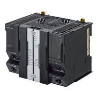
Omron NX102 series User Manual (280 pages)
Machine Automation Controller, CPU Unit Built-in EtherCAT Port
Brand:
Omron
| Category:
Controller
| Size: 18 MB
Table of Contents
Intended Audience
3
Applicable Products
3
Relevant Manuals
5
Manual Structure
8
Page Structure
8
Special Information
9
Precaution on Terminology
9
Sections in this Manual
11
Table of Contents
12
Terms and Conditions Agreement
16
Warranty, Limitations of Liability
16
Application Considerations
17
Disclaimers
17
Safety Precautions
19
Precautions for Safe Use
20
Precautions for Correct Use
21
Regulations and Standards
22
Versions
23
Checking Versions
23
Unit Versions of CPU Units and Sysmac Studio Versions
27
Related Manuals
28
Revision History
31
Introduction
33
Introduction to Ethercat
34
Ethercat Features
34
Ethercat Communications
34
Ethercat Features for NJ/NX-Series CPU Units
35
System Configuration and Configuration Devices
36
System Configuration
36
Determining the Network Configuration
40
Specifications of Built-In Ethercat Port
42
Overview of Communications
44
Process Data Communications and SDO Communications
44
Other Functions
44
Ethercat Communications Procedure
47
Overview
47
Details
47
Section 2 Part Names and Slave Settings
52
Part Names and Functions
52
Built-In Ethercat Port Indicators
52
Windows Used in Sysmac Studio
54
Connecting the Sysmac Studio
57
Setting the Node Addresses of the Ethercat Slaves
59
Setting Node Address Using Hardware Switches
59
Setting the Node Address from the Sysmac Studio
60
Features of Sysmac Devices
62
Sysmac Devices
62
Sysmac Device Features
62
List of Sysmac Devices
64
Sysmac Device Features and Ethercat Masters
65
Section 3 Ethercat Communications
70
Ethercat Communications
70
Ethercat Communications Types and Settings
70
Coe (CAN Application Protocol over Ethercat)
70
Types of Communications
72
Types of Ethercat Variables
74
Settings Required for Ethercat Communications
75
Programming Ethercat Communications
76
State Transitions for Ethercat Communications
77
Self Diagnosis at Startup
77
Control States for Ethercat Communications
77
Ethercat Status in Relation to CPU Unit Status
79
Ethercat Network Wiring
81
Section 4 Ethercat Network Wiring
82
Supported Network Topologies
82
Line/Daisy Chain Topology
82
Branching Topology
82
Ring Topology
84
Precautions for Using Junction Slaves
90
Laying the Ethercat Network
92
Installation Precautions
92
Installing Ethercat Communications Cables
93
Connecting Communications Cables
96
Cable Connection Procedure
98
Setting up Ethercat Communications with the Sysmac Studio
99
Section 5 Setting up Ethercat Communications with the Sysmac
100
Overview of Network Configuration Information
100
Creating the Ethercat Network Configuration
101
Procedure to Create the Ethercat Network Configuration
101
Cable Redundancy Setting
103
Setting Ethercat Slave Variables and Axes
107
Registering Device Variables for All Ethercat Slaves
107
Axis Settings for Servo Drives and Encoder Input Slaves
111
Ethercat Master Parameter Settings
112
Ethercat Slave Parameter Settings
118
Changing the PDO Map Settings
121
Ethercat Slave Enable/Disable Settings
123
Comparing and Merging Ethercat Network Configurations
126
Introduction for Comparing and Merging Ethercat Network Configurations
126
Introduction for Comparing and Merging Ethercat Network Configu- Rations
126
Operation Procedure for Comparing and Merging Ethercat Network Configurations
126
When Compare and Merge with Actual Network Configuration Dialog Box Is Not Displayed
130
When Slaves on Actual Network Configuration Are Not Displayed
137
Automatically Creating the Network Configuration
138
Using the Sysmac Studio to Obtain Serial Numbers from the Actual Network Configuration
141
Using the Sysmac Studio to Obtain Serial Numbers from the Ac- Tual Network Configuration
141
Downloading the Network Configuration Information from the Sysmac Studio
143
Confirming Communications after Completing Ethercat Configuration and Settings5-47
145
Confirming Communications after Completing Ethercat Configuration and Settings
145
Process Data Communications (PDO Communications)
148
Allocated Variables for Process Data Communications
148
Process Data Communications Refresh Timing
149
Checking Validity of Process Data
152
System Response Time in Process Data Communications
157
I/O Operations for Major Fault Level Controller Errors and I/O Refreshing with Specified Values
161
SDO Communications
165
Ethercat Communications Instructions
165
Sample Programming
165
Execution Timing of SDO Communications
167
Minimum Message Response Time for SDO Communications
167
Instructions Used in Ethercat Communications
171
Ethercat Communications Instructions
171
System-Defined Variables that Are Related to the Built-In Ethercat Port
174
What Are System-Defined Variables
174
System-Defined Variables
174
Ethercat Master Function Module, Category Name
181
Example of Operations for Ethercat Communications
193
8-1 Example of Operations for Ethercat Communications
194
System Configuration Example
194
Wiring and Settings
194
Setting the Ethercat Network Configuration
194
Programming
196
Offline Debugging
197
Turning the Power on
197
Online Debugging
197
Downloading the Network Configuration Information and the User Program
197
Confirming the Start of Communications
197
Troubleshooting
199
Overview of Troubleshooting
200
How to Check for Errors
200
Errors Related to the Ethercat Master Function Module
200
Troubleshooting
201
Error Table
201
Error Descriptions
201
Resetting Errors
201
Diagnostic and Statistical Information
201
Identifying an Error Slave and Cause of Error
219
Precautions When Connecting or Disconnecting Slaves During Communications
223
Procedure for Connecting and Disconnecting Slaves During Communications
223
Procedure for Connecting and Disconnecting Slaves During Commu- Nications
223
Prohibition to Physically Disconnecting a Slave and Resetting an Error or Connecting a Slave at the same Time
223
Prohibition to Physically Disconnecting a Slave and Resetting an Er- Ror or Connecting a Slave at the same Time
223
Replacing Slaves During Communications
224
Introduction
224
Slave Replacement Methods
225
Backing up Settings
226
Restoring Settings
228
Replacement Procedure
230
Appendices
237
Ethercat Status in Relation to CPU Unit Status
238
A-1-1 When the Power Supply Is Turned on
238
When the Power Supply Is Turned on
238
A-1-2 CPU Unit Operating Modes
239
A-1-3 Controller Errors Other than Errors in the Built-In Ethercat Master
240
A-1-4 Others
241
A-1-5 When the Power Supply Is Turned off
242
A-2 Monitoring Packets
243
A-3 Multi-Vendor Environments
251
A-3-1 Ethercat Slave Information File (ESI Files
251
Ethercat Slave Information File (ESI Files
251
A-3-2 Connecting Slaves from Other Manufacturers to an OMRON Master
252
A-3-3 Installing ESI Files
252
Editing PDO Entry Tables
257
Settings for MDP-Compatible Slaves from Other Manufacturers
263
A-5 Terminology
267
Setting Transmission Delay Time by Actual Measurement
267
Version Information
267
A-5 Terminology
269
A-6-1 Functions that Were Added or Changed for each Unit Version
271
Differences between Project Unit Version Earlier than 1.40 and Project Unit Version 1.40 or Later
271
A-6 Version Information
271
A-6-2 Differences between Project Unit Version Earlier than 1.40 and Project Unit Version 1.40 or Later
271
Advertisement
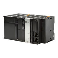
Omron NX102 series User Manual (256 pages)
NX-series; NJ-series Machine Automation Controller CPU Unit Built-in EtherCAT Port
Brand:
Omron
| Category:
Controller
| Size: 13 MB
Table of Contents
Introduction
3
Intended Audience
3
Applicable Products
3
Relevant Manuals
4
Nx701
4
Nx1P2
5
Manual Structure
6
Page Structure
6
Special Information
6
Precaution on Terminology
7
Sections in this Manual
9
Table of Contents
10
Terms and Conditions Agreement
14
Warranty, Limitations of Liability
14
Application Considerations
15
Disclaimers
15
Safety Precautions
16
Precautions for Safe Use
17
Precautions for Correct Use
18
Regulations and Standards
19
Conformance to EU Directives
19
Conformance to Shipbuilding Standards
20
Software Licenses and Copyrights
20
Versions
21
Checking Versions
21
Unit Versions of CPU Units and Sysmac Studio Versions
24
Related Manuals
25
Nj101
25
Nj101
26
Revision History
28
W505-E1
28
Nx102
29
Introduction
31
Introduction to Ethercat
32
Ethercat Features
32
Ethercat Communications
32
Ethercat Features for NJ/NX-Series CPU Units
33
System Configuration and Configuration Devices
34
System Configuration
34
Determining the Network Configuration
38
Specifications of Built-In Ethercat Port
39
1-3-1 Performance Specifications
39
Nx1P2
39
Nj101
40
Introduction of Communications
42
Process Data Communications and SDO Communications
42
Other Functions
42
Ethercat Communications Procedure
44
Overview
44
Details
45
Part Names and Slave Settings
49
Section 2 Part Names and Slave Settings
50
Part Names and Functions
50
Built-In Ethercat Port Indicators
50
Windows Used in Sysmac Studio
52
Connecting the Sysmac Studio
55
Setting the Node Addresses of the Ethercat Slaves
57
Features of Sysmac Devices
60
Sysmac Devices
60
Sysmac Device Features
60
List of Sysmac Devices
63
Sysmac Device Features and Ethercat Masters
64
Section 3 Ethercat Communications
68
Ethercat Communications
68
Ethercat Communications Types and Settings
68
Coe (CAN Application Protocol over Ethercat)
68
Types of Communications
71
Types of Ethercat Variables
72
Settings Required for Ethercat Communications
73
Programming Ethercat Communications
74
State Transitions for Ethercat Communications
75
Self Diagnosis at Startup
75
Control States for Ethercat Communications
75
CPU Unit Status in Relation to Ethercat
77
Ethercat Network Wiring
79
Section 4 Ethercat Network Wiring
80
Laying the Ethercat Network
80
Supported Network Topologies
80
Installation Precautions
82
Installing Ethercat Communications Cables
82
Connecting Communications Cables
86
Cable Connection Procedure
87
Setting up Ethercat Communications with the Sysmac Studio
89
Section 5 Setting up Ethercat Communications with
90
Overview of Network Configuration Information
90
Creating the Ethercat Network Configuration
91
Setting Ethercat Slave Variables and Axes
94
Registering Device Variables for All Ethercat Slaves
94
Axis Settings for Servo Drives and Encoder Input Slaves
98
Ethercat Master and Slave Parameter Settings
99
Setting Ethercat Master
99
Setting Ethercat Slaves
104
Comparing and Merging Ethercat Network Configurations
112
Comparing and Merging with the Actual Network Configuration from the Sysmac Studio
112
Automatically Creating the Network Configuration
117
Using the Sysmac Studio to Obtain Serial Numbers from the Actual Network Configuration
120
Downloading the Network Configuration Information
122
Downloading the Network Configuration Information from the Sysmac Studio
122
Confirming Communications after Completing Ethercat Configuration and Settings
124
Process Data Communications (PDO Communications)
128
Allocated Variables for Process Data Communications
128
Process Data Communications Refresh Timing
130
Checking the Validity of the Process Data
133
System Response Time in Process Data Communications
138
I/O Operations for Major Fault Level Controller Errors and I/O Refreshing with Specified Values
142
SDO Communications
146
Ethercat Instructions
146
Sample Programming
147
Execution Timing of SDO Communications
148
Minimum Message Response Time for SDO Communications
149
Instructions Used in Ethercat Communications
153
Ethercat Instructions
153
7-1 System-Defined Variables that Are Related to the Built-In Ethercat Port
156
What Are System-Defined Variables
156
System-Defined Variables that Are Related to the Built-In Ethercat Port
156
System-Defined Variables
157
Ethercat Master Function Module, Category Name: _EC
163
Example of Operations for Ethercat Communications
173
8-1 Example of Operations for Ethercat Communications
174
System Configuration Example
174
Wiring and Settings
174
Setting the Ethercat Network Configuration
175
Programming
177
Offline Debugging
177
Turning the Power on
177
Online Debugging
177
Downloading the Network Configuration Information and the User Program
177
Confirming the Start of Communications
178
Troubleshooting
179
Overview of Errors
180
How to Check for Errors
181
Errors Related to the Ethercat Master Function Module
181
Troubleshooting
182
Diagnostic and Statistical Information
182
Error Table
182
Error Descriptions
182
Resetting Errors
182
Identifying an Error Slave and Cause of Error
200
Precautions When Connecting or Disconnecting Slaves During Communications
204
Procedure for Connecting and Disconnecting Slaves During Communications
204
Prohibition to Physically Disconnecting a Slave and Resetting an Error or Connecting a Slave at the same Time
204
Precautions When Connecting or Disconnecting Slaves During
204
Communications
204
Procedure for Connecting and Disconnecting Slaves During
204
Replacing Slaves During Communications
205
Introduction
205
Slave Replacement Methods
206
Backing up Settings
207
Restoring Settings
208
Replacement Procedure
210
Appendices
215
Ethercat Status in Relation to CPU Unit Status
216
A-1-1 When the Power Supply Is Turned on
216
When the Power Supply Is Turned on
216
A-1-2 CPU Unit Operating Modes
217
A-1-3 Controller Errors Other than Errors in the Built-In Ethercat Master
219
A-1-4 Others
220
A-1-5 When the Power Supply Is Turned off
221
Monitoring Packets
222
Multi-Vendor Environments
231
A-3-1 Ethercat Slave Information File (ESI Files
231
Ethercat Slave Information File (ESI Files
231
Connecting Slaves from Other Manufacturers to an OMRON Master
233
Installing ESI Files
233
A-3-4 Editing PDO Entry Tables
239
A-3-5 Settings for MDP-Compatible Slaves from Other Manufacturers
244
Glossary
247
Version Information
249
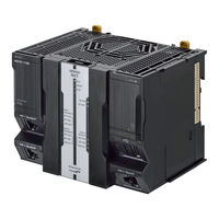
Omron NX102 series Hardware User Manual (218 pages)
Machine Automation Controller
Brand:
Omron
| Category:
Controller
| Size: 7 MB
Table of Contents
Intended Audience
3
Applicable Products
3
Relevant Manuals
4
Manual Structure
6
Page Structure
6
Special Information
7
Precaution on Terminology
7
Sections in this Manual
9
Table of Contents
10
Terms and Conditions Agreement
14
Warranty, Limitations of Liability
14
Application Considerations
15
Disclaimers
15
Statement of Security Responsibilities for Assumed Use Cases and against Threats
16
Safety Precautions
17
Definition of Precautionary Information
17
Symbols
17
Warning
18
Cautions
21
Precautions for Safe Use
23
Precautions for Correct Use
34
Regulations and Standards
39
Conformance to EU Directives
39
Conformance to UL and CSA Standards
40
Conformance to KC Certification
40
Conformance to Shipbuilding Standards
40
Software Licenses and Copyrights
41
Versions
42
Checking Versions
42
Unit Versions of CPU Units and Sysmac Studio Versions
44
Related Manuals
45
Terminology
48
Revision History
53
Introduction to NX-Series Controllers
55
The NX-Series Controller
56
Features
57
Introduction to the System Configurations
60
Specifications
63
Overall Operating Procedure for the CPU Unit
68
Overall Procedure
68
Procedure Details
69
System Configuration
73
Basic System Configuration
74
Ethercat Network Configuration
75
NX Unit Configuration
76
Connecting to the Sysmac Studio
78
Network Configuration
79
CPU Units
82
Models and Specifications
82
Part Names and Functions
84
DIP Switch
86
Operation Status Indicators
88
Terminal Blocks
92
Battery
93
ID Information Indication
94
SD Memory Cards
96
Models and Specifications
96
Purpose
96
Power Supply-Related Units
97
NX Units
98
Sysmac Studio
99
Model Numbers
99
Connection
99
Designing the Power Supply System
101
Power Supply System
102
NX Unit Power Supply and I/O Power Supply
102
NX-Series Power Supply-Related Units
103
User's Manual (Cat. No. W523)
104
Designing the NX Unit Power Supply System
110
Procedure for Designing the NX Unit Power Supply System
110
Calculation Example for the NX Unit Power Supply
111
Designing the I/O Power Supply System
113
I/O Power Supply Method
113
Designing the I/O Power Supply from the NX Bus
114
Designing the I/O Power Supply from External Sources
119
Restrictions on Inrush Current for ON/OFF Operation
120
Selecting External Power Supplies and Protective Devices
121
Selecting the Unit Power Supply
121
Selecting the I/O Power Supplies
123
Selecting Protective Devices
124
Installation and Wiring
129
Processing at Power on and Power off
130
Power on Operation
130
Power off Operation
131
Resetting the Controller from the Sysmac Studio
133
Fail-Safe Circuits
134
Mounting and Removing Units
136
Installation in a Control Panel
136
Preparations for Installation
140
Installing the CPU Unit
142
Attaching Markers
145
Installing and Connecting NX Units
146
Mounting the End Cover
149
Mounting the End Plates
150
Installing and Removing the SD Memory Card
151
Battery Installation
154
Removing CPU Unit
156
Removing NX Units
157
Assembled Appearance and Dimensions
159
Wiring
162
Wiring the Unit Power Supply
162
CPU Unit
162
Wiring the Additional NX Unit Power Supply Unit
163
Wiring the Additional I/O Power Supply Unit
163
Wiring the Protective Devices
163
Grounding
163
Electrically Connected to
165
DIN Track Contact Plate
165
Ground Terminal (Functional Ground Terminal)
165
Additional NX Unit Power Supply Unit
165
Shield Connection Unit
165
Wiring the Built-In Ethercat Port
167
Wiring the Built-In Ethernet/Ip Port
167
DIN Track
167
Wiring to the CPU Unit Terminal Block
168
Control Panel Installation
183
Temperature
183
Humidity
184
Vibration and Shock
185
Atmosphere
185
Electrical Environment
185
Grounding
190
Troubleshooting
195
Overview of Troubleshooting
196
Inspection and Maintenance
197
Cleaning and Maintenance
198
Cleaning
198
Periodic Inspections
199
Unit Replacement Precautions
200
Replacing the Battery
202
The CPU Unit
202
Appendices
205
A-1 Specifications
206
A-2 Dimensions
207
A-2-1 NX-Series NX102 CPU Unit
207
NX-Series NX102 CPU Unit
207
A-2-2 End Cover
208
A-2-3 SD Memory Card
208
End Cover
208
List of Terminal Block Models
209
A-3-1 Model Notation
209
A-3-2 List of Terminal Block Models
209
Ground Terminal
209
A-4 Version Information
211
Support Functions of the CPU Units and Restrictions on the NX Units
212
Advertisement
Omron NX102 series Connection Manual (50 pages)
Machine Automation Controller
Brand:
Omron
| Category:
Controller
| Size: 1 MB
Table of Contents
Table of Contents
3
Related Manuals
4
Terms and Definitions
5
Precautions
6
Overview
7
Applicable Devices and Device Configuration
8
Applicable Devices
8
Device Configuration
9
Communications Settings
11
Ethercat Connection Parameter
11
IO-Link Connection Parameter
11
Slave Terminal Configuration and Device Names
11
Device Variables
12
IO-Link Connection Procedure
13
Work Flow
13
Slave Terminal Setup
15
Hardware Settings
15
Network Configuration for Host Communications
18
IO-Link Master Unit Setup
23
Parameter Settings
23
Controller Setup
26
IO-Link Communication Status Check
33
Checking the Connection Status
33
Initialization Method
45
Initializing a Slave Terminal
45
Initializing a Controller
48
Revision History
49
Omron NX102 series Firmware Update Instruction (44 pages)
Machine Automation Controller
Brand:
Omron
| Category:
Controller
| Size: 0 MB
Table of Contents
Introduction
3
Intended Audience
3
Applicable Products
3
Manual Structure
4
Page Structure
4
Special Information
5
Sections in this Manual
7
Table of Contents
8
Terms and Conditions Agreement
10
Warranty, Limitations of Liability
10
Application Considerations
11
Disclaimers
11
Statement of Security Responsibilities for Assumed Use Cases and against Threats
12
Safety Precautions
13
Precautions for Safe Use
14
Precautions for Correct Use
16
Regulations and Standards
18
Versions
19
Related Manuals
20
Terminology
22
Revision History
23
Restrictions on Firmware Update
25
Restrictions
26
Performing Firmware Update
29
Procedures to Perform Firmware Update
30
Operation Status Indicators
34
Troubleshooting
37
Troubleshooting During Firmware Update
38
Appendices
39
A-1 Formatting SD Memory Cards
40
Omron NX102 series Network Connection Manual (48 pages)
Machine Automation Controller PATLITE IO-Link Signal Tower LR6-IL Connection
Brand:
Omron
| Category:
Controller
| Size: 2 MB
Table of Contents
Table of Contents
3
1 Related Manuals
4
2 Terms and Definitions
5
3 Precautions
6
4 Overview
7
5 Applicable Devices and Device Configuration
8
Applicable Devices
8
Device Configuration
9
6 Communications Settings
11
Ethercat Connection Parameter
11
IO-Link Connection Parameters
11
Slave Terminal Configuration and Device Names
11
Device Variables
12
7 IO-Link Connection Procedure
13
Work Flow
13
Slave Terminal Setup
15
Network Configuration for Host Communications
17
IO-Link Master Unit Setup
22
Controller Setup
26
IO-Link Communication Status Check
33
8 Initialization Method
43
Initializing a Slave Terminal
43
Initializing a Controller
46
9 Revision History
47
Omron NX102 series Network Connection Manual (44 pages)
Machine Automation Controller, HMS Industrial Networks AB, Anybus X-gateway EtherNet/IP Adapter
Brand:
Omron
| Category:
Controller
| Size: 1 MB
Table of Contents
Table of Contents
3
Related Manuals
4
Terms and Definitions
5
Precautions
6
Overview
7
Applicable Devices and Device Configuration
8
Applicable Devices
8
Device Configuration
9
Ethernet/Ip Settings
11
Parameters
11
Global Variables
12
Tag Sets
13
Connection Settings
14
Ethernet/Ip Connection Procedure
15
Work Flow
15
HMS X-Gateway Setup
17
Controller Setup
23
Ethernet/Ip Communication Status Check
40
Initialization Method
42
Initializing a Controller
42
Revision History
43
Advertisement
Related Products
Omron NX102-1
Omron NX102-1220
Omron NX102-1200
Omron NX102-1120
Omron NX102-1100
Omron NX102-1020
Omron NX102-1000
Omron NX102-9020
Omron NX102-9000
Omron SYSMAC NX102 20 Series
Omron Categories
Blood Pressure Monitor
Controller
Accessories
Switch
Inverter
More Omron Manuals
Login
Sign In
OR
Sign in with Facebook
Sign in with Google
Upload manual
Upload from disk
Upload from URL