Table of Contents
Troubleshooting

Subscribe to Our Youtube Channel
Related Manuals for Omron sysmac NX102-9 Series


Summary of Contents for Omron sysmac NX102-9 Series
- Page 1 Machine Automation Controller NJ/NX-series CPU Unit Built-in EtherNet/IP Port User’s Manual NX701-1 NX102-1 NX102-9 NX1P2-1 NX1P2-9 NJ501- NJ301-1 NJ101-10 NJ101-90 CPU Unit W506-E1-21...
- Page 2 No patent liability is assumed with respect to the use of the information contained herein. Moreover, because OMRON is constantly striving to improve its high-quality products, the information contained in this manual is subject to change without notice. Every precaution has been taken in the preparation of this manual. Neverthe- less, OMRON assumes no responsibility for errors or omissions.
-
Page 3: Introduction
Introduction Introduction Thank you for purchasing an NJ/NX-series CPU Unit. This manual contains information that is necessary to use the NJ/NX-series CPU Unit. Please read this manual and make sure you understand the functionality and performance of the NJ/NX-series CPU Unit before you attempt to use it in a control system. -
Page 4: Relevant Manuals
Relevant Manuals Relevant Manuals The following table provides the relevant manuals for the NJ/NX-series CPU Units. Read all of the manuals that are relevant to your system configuration and application before you use the NJ/NX-series CPU Unit. Most operations are performed from the Sysmac Studio Automation Software. Refer to the Sysmac Stu- dio Version 1 Operation Manual (Cat. - Page 5 Relevant Manuals Manual Basic information Purpose of use Writing the user program Using motion control Using EtherCAT Using EtherNet/IP Using OPC UA Using FINS Using the database connection service Using the GEM Services ...
-
Page 6: Manual Structure
Manual Structure Manual Structure Page Structure The following page structure is used in this manual. Level 1 heading 4 Installation and Wiring Level 2 heading Level 3 heading Mounting Units Level 2 heading Gives the current Level 3 heading headings. 4-3-1 Connecting Controller Components The Units that make up an NJ-series Controller can be connected simply by pressing the Units together... - Page 7 Manual Structure Special Information Special information in this manual is classified as follows: Precautions for Safe Use Precautions on what to do and what not to do to ensure safe usage of the product. Precautions for Correct Use Precautions on what to do and what not to do to ensure proper operation and performance. Additional Information Additional information to read as required.
- Page 8 Manual Structure NJ/NX-series CPU Unit Built-in EtherNet/IP Port User’s Manual (W506)
- Page 9 Sections in this Manual Sections in this Manual Modbus TCP Master Introduction Function Installing Ethernet FTP Server Networks System-defined Variables Related to the Built-in Eth- FTP Client erNet/IP Port Determining Automatic Clock IP Addresses Adjustment Sysmac Studio Settings for the Built-in Ether- SNMP Agent Net/IP Port Communications Per-...
-
Page 10: Table Of Contents
CONTENTS CONTENTS Introduction ....................... 1 Relevant Manuals ...................... 2 Manual Structure ....................... 4 Sections in this Manual .................... 7 Terms and Conditions Agreement ................. 15 Safety Precautions ....................17 Precautions for Safe Use..................18 Precautions for Correct Use................... 19 Regulations and Standards..................20 Versions ........................ - Page 11 CONTENTS 2-1-1 Recommended Network Devices ....................2-2 2-1-2 Ethernet Switch Types ........................ 2-3 2-1-3 Ethernet Switch Functions ......................2-3 2-1-4 Precautions for Ethernet Switch Selection.................. 2-4 Network Installation ........................ 2-6 2-2-1 Basic Installation Precautions..................... 2-6 2-2-2 Recommended Network Devices ....................2-6 2-2-3 Precautions When Laying Twisted-pair Cable ................
- Page 12 CONTENTS Section 7 Tag Data Link Functions Introduction to Tag Data Links ....................7-2 7-1-1 Tag Data Links ..........................7-2 7-1-2 Data Link Data Areas ........................7-3 7-1-3 Tag Data Link Functions and Specifications ................7-6 7-1-4 Overview of Operation ........................ 7-7 7-1-5 Starting and Stopping Tag Data Links..................
- Page 13 CONTENTS CIP Object Services....................... 8-47 8-5-1 CIP Objects Sent to the Built-in EtherNet/IP Port ..............8-47 8-5-2 Identity Object (Class ID: 01 hex) ..................... 8-47 8-5-3 NX Configuration Object (Class ID: 74 hex) ................8-50 8-5-4 TCP/IP Interface Object (Class ID: F5 hex)................8-72 8-5-5 Ethernet Link Object (Class ID: F6 hex) ...................
- Page 14 CONTENTS Section 11 FTP Server 11-1 Overview and Specifications ....................11-2 11-1-1 Overview ........................... 11-2 11-1-2 Specifications ..........................11-2 11-2 FTP Server Function Details....................11-3 11-2-1 Supported Files ......................... 11-3 11-2-2 Connecting to the FTP Server....................11-3 11-3 Using the FTP Server Function .................... 11-6 11-3-1 Procedure..........................
- Page 15 CONTENTS Section 15 Communications Performance and Communications Load 15-1 Communications System...................... 15-2 15-1-1 Tag Data Link Communications Method ................... 15-2 15-1-2 Calculating the Number of Connections ................... 15-4 15-1-3 Packet Interval (RPI) Accuracy ....................15-5 15-2 Adjusting the Communications Load .................. 15-6 15-2-1 Checking Bandwidth Usage for Tag Data Links................
- Page 16 CONTENTS A-8 Example of NX Unit Setting Using NX Configuration Object Service.......A-69 A-8-1 Changing the Unit Operation Settings for Singe NX Unit............A-69 A-8-2 Changing the Unit Operation Settings for Multiple NX Units.............A-70 A-8-3 Initializing the Unit Operation Settings for Singe NX Unit ............A-71 A-9 Version Information .......................A-72 Index NJ/NX-series CPU Unit Built-in EtherNet/IP Port User’s Manual (W506)
-
Page 17: Terms And Conditions Agreement
Omron’s exclusive warranty is that the Products will be free from defects in materials and workman- ship for a period of twelve months from the date of sale by Omron (or such other period expressed in writing by Omron). Omron disclaims all other warranties, express or implied. - Page 18 Disclaimers Performance Data Data presented in Omron Company websites, catalogs and other materials is provided as a guide for the user in determining suitability and does not constitute a warranty. It may represent the result of Omron’s test conditions, and the user must correlate it to actual application requirements. Actual perfor- mance is subject to the Omron’s Warranty and Limitations of Liability.
-
Page 19: Safety Precautions
Safety Precautions Safety Precautions Refer to the following manuals for safety precautions. • NX-series CPU Unit Hardware User’s Manual (Cat. No. W535) • NX-series NX102 CPU Unit Hardware User’s Manual (Cat. No. W593) • NX-series NX1P2 CPU Unit Hardware User’s Manual (Cat. No. W578) •... -
Page 20: Precautions For Safe Use
Precautions for Safe Use Precautions for Safe Use Refer to the following manuals for precautions for safe use. • NX-series CPU Unit Hardware User’s Manual (Cat. No. W535) • NX-series NX102 CPU Unit Hardware User’s Manual (Cat. No. W593) • NX-series NX1P2 CPU Unit Hardware User’s Manual (Cat. No. W578) •... -
Page 21: Precautions For Correct Use
Precautions for Correct Use Precautions for Correct Use Refer to the following manuals for precautions for correct use. • NX-series CPU Unit Hardware User’s Manual (Cat. No. W535) • NX-series NX102 CPU Unit Hardware User’s Manual (Cat. No. W593) • NX-series NX1P2 CPU Unit Hardware User’s Manual (Cat. No. W578) •... -
Page 22: Regulations And Standards
Concepts EMC Directive OMRON devices that comply with EU Directives also conform to the related EMC standards so that they can be more easily built into other devices or the overall machine. The actual products have been checked for conformity to EMC standards.* Whether the products conform to the standards in the system used by the customer, however, must be checked by the customer. - Page 23 The NJ/NX-series Controllers comply with the following shipbuilding standards. Applicability to the shipbuilding standards is based on certain usage conditions. It may not be possible to use the prod- uct in some locations. Contact your OMRON representative before attempting to use a Controller on a ship.
-
Page 24: Versions
Versions Versions Hardware revisions and unit versions are used to manage the hardware and software in NJ/NX-series Units and EtherCAT slaves. The hardware revision or unit version is updated each time there is a change in hardware or software specifications. Even when two Units or EtherCAT slaves have the same model number, they will have functional or performance differences if they have different hard- ware revisions or unit versions. - Page 25 Versions The ID information on an NX-series NX1P2- CPU Unit is shown below. MAC address PORT1 : PORT2 : Ver.1. HW Rev. Unit version Hardware revision LOT No. DDMYY xxxx ID information indication Lot number Serial number Note The hardware revision is not displayed for the Unit that the hardware revision is in blank. The ID information on an NJ-series NJ501-...
- Page 26 Versions Right-click CPU Rack under Configurations and Setup - CPU/Expansion Racks in the Multi- view Explorer and select Production Information. The Production Information Dialog Box is displayed. Checking the Unit Version of an NJ-series CPU Unit You can use the Production Information while the Sysmac Studio is online to check the unit version of a Unit.
- Page 27 Versions Changing Information Displayed in Production Information Dialog Box Click the Show Detail or Show Outline Button at the lower right of the Production Information Dialog Box. The view will change between the production information details and outline. Outline View Detail View Unit Versions of CPU Units and Sysmac Studio Versions The functions that are supported depend on the unit version of the NJ/NX-series CPU Unit.
-
Page 28: Related Manuals
Related Manuals Related Manuals The followings are the manuals related to this manual. Use these manuals for reference. Manual name Cat. No. Model numbers Application Description NX-series CPU Unit W535 NX701- Learning the basic specifi- An introduction to the entire NX701 system is pro- Hardware User’s Manual cations of the NX701 CPU vided along with the following information on the... - Page 29 Related Manuals Manual name Cat. No. Model numbers Application Description NJ/NX-series Instruc- W502 NX701- Learning detailed specifica- The instructions in the instruction set (IEC 61131-3 tions Reference Manual NX102- tions on the basic instruc- specifications) are described. NX1P2- tions of an NJ/NX-series NJ501-...
-
Page 30: Revision History
Revision History Revision History A manual revision code appears as a suffix to the catalog number on the front and back covers of the manual. W506-E1-21 Cat. No. Revision code Revision code Date Revised content July 2011 Original production March 2012 •... - Page 31 Revision History Revision code Date Revised content October 2016 • Added information on the NX1P2- NX-series CPU Units. • Added information on functional support for unit version 1.13 of the CPU Units. • Corrected mistakes. April 2017 • Added information on functional support for unit version 1.14 of the CPU Units.
- Page 32 Revision History NJ/NX-series CPU Unit Built-in EtherNet/IP Port User’s Manual (W506)
-
Page 33: Introduction
Introduction 1-1 Introduction ..........1-2 1-1-1 EtherNet/IP Features . -
Page 34: Ethernet/Ip Features
1 Introduction Introduction 1-1-1 EtherNet/IP Features EtherNet/IP is an industrial multi-vendor network that uses Ethernet. The EtherNet/IP specifications are open standards managed by the ODVA (Open DeviceNet Vendor Association), just like DeviceNet. Eth- erNet/IP is not just a network between Controllers. It is also used as a field network. Because Ether- Net/IP uses standard Ethernet technology, various general-purpose Ethernet devices can be used in the network. -
Page 35: Features Of Built-In Ethernet/Ip Port On Nj/Nx-Series Cpu Units
1 Introduction 1-1-2 Features of Built-in EtherNet/IP Port on NJ/NX-series CPU Units Tag Data Links Cyclic communications between Controllers or between Controllers and other devices are possible on an EtherNet/IP network. Tag data links can quickly perform data exchanges. ... - Page 36 1 Introduction Network Management with an SNMP Manager The SNMP agent passes internal status information from the built-in EtherNet/IP port to network management software that uses an SNMP manager. * A separate SNMP manager is necessary for network management. ...
-
Page 37: System Configuration And Configuration Devices
NJ501-, 301- or 101- work. NJ-series CPU Unit (built-in EtherNet/IP port) NX701-, NX102- or NX1P2- NX-series CPU Unit (built-in EtherNet/IP port) OMRON PLCs CJ2H-CPU-EIP or CJ2M-CPU3 CJ2 CPU Unit (built-in EtherNet/IP port) CJ-series CJ1W-EIP21 EtherNet/IP Unit* CS-series CS1W-EIP21 EtherNet/IP Unit (2) Twisted-pair cable The twisted-pair cable has a RJ45 Modular Connector at each end. -
Page 38: Support Software Required To Construct A Network
1 Introduction 1-2-2 Support Software Required to Construct a Network This section describes the Support Software that is required to construct an EtherNet/IP network. The built-in EtherNet/IP port has Ethernet Settings and Tag Data Link Settings, which are stored in the non- volatile memory of the CPU Unit. -
Page 39: Built-In Ethernet/Ip Port
1 Introduction Built-in EtherNet/IP Port 1-3-1 Specifications Specifications NX701- NX102- NX1P2- NJ501-/NJ301- NJ101- / Item Unit ver- Unit ver- Unit ver- Unit ver- Unit ver- Unit ver- sion 1.10 sion 1.30 sion 1.13 sion 1.00 sion 1.03 sion 1.10 or later or later... - Page 40 1 Introduction Specifications NX701- NX102- NX1P2- NJ501-/NJ301- NJ101- / Item Unit ver- Unit ver- Unit ver- Unit ver- Unit ver- Unit ver- sion 1.10 sion 1.30 sion 1.13 sion 1.00 sion 1.03 sion 1.10 or later or later or later to 1.02...
- Page 41 1 Introduction Specifications NX701- NX102- NX1P2- NJ501-/NJ301- NJ101- / Item Unit ver- Unit ver- Unit ver- Unit ver- Unit ver- Unit ver- sion 1.10 sion 1.30 sion 1.13 sion 1.00 sion 1.03 sion 1.10 or later or later or later to 1.02...
- Page 42 1 Introduction Specifications NX701- NX102- NX1P2- NJ501-/NJ301- NJ101- / Item Unit ver- Unit ver- Unit ver- Unit ver- Unit ver- Unit ver- sion 1.10 sion 1.30 sion 1.13 sion 1.00 sion 1.03 sion 1.10 or later or later or later to 1.02...
-
Page 43: Part Names And Functions
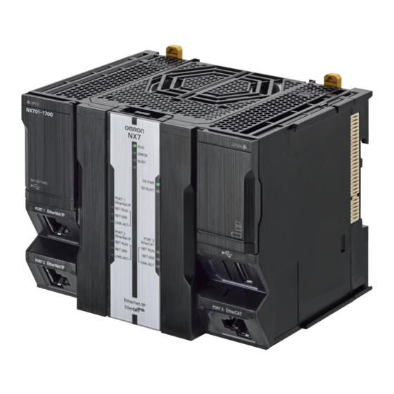
1 Introduction 1-3-2 Part Names and Functions Parts and Names NX701 CPU Unit ERROR BUSY SHTDWN SD PWR SD BUSY PORT1 EtherNet/IP NET RUN NET ERR Indicators LINK/ACT PORT1 EtherNet/IP PORT2 PORT3 EtherNet/IP EtherCAT NET RUN NET RUN Built-in EtherNet/IP USB port NET ERR NET ERR... - Page 44 1 Introduction NX102 CPU Unit PORT1 EtherNet/IP Built-in EtherNet/IP port 1 Indicators PORT2 EtherNet/IP Built-in EtherNet/IP port 2 PORT3 EtherCAT Built-in EtherCAT port MAC Address Notation A specific MAC address is allocated to each device connected to the Ethernet network. The built-in EtherNet/IP port’s MAC address is listed in 12-digit hexadecimal in the place shown below on the CPU Unit.
- Page 45 1 Introduction NX1P2 CPU Unit SW SETTING POWER PORT1 EtherNet/IP ERROR BUSY Built-in EtherNet/IP port SD PWR SD BUSY PORT1 EtherNet/IP NET RUN PORT2 EtherCAT NET ERR LINK/ACT PORT2 EtherCAT NETRUN NET ERR LINK/ACT Indicators MAC Address Notation A specific MAC address is allocated to each device connected to the Ethernet network. The built-in EtherNet/IP port's MAC address is listed in 12-digit hexadecimal in the place shown below on the CPU Unit.
- Page 46 1 Introduction NJ-series CPU Unit USB port Built-in EtherNet/IP port Built-in EtherCAT port Indicators MAC Address Notation A specific MAC address is allocated to each device connected to the Ethernet network. The built-in EtherNet/IP port’s MAC address is listed in 12-digit hexadecimal in the two places shown below on the CPU Unit.
- Page 47 1 Introduction Indicators (LEDs) PORT1 EtherNet/IP EtherNet/IP PORT1 NET RUN NET RUN NET ERR NET ERR LINK/ACT LINK/ACT Bottom indicators PORT2 PORT3 EtherNet/IP EtherCAT NET RUN NET RUN NET ERR NET ERR LINK/ACT LINK/ACT NX701 CPU Unit NX102 CPU Unit NX1P2 CPU Unit NJ-series CPU Unit ...
- Page 48 1 Introduction Indicator Color Status Operating status Link not established. Not lit • The cable is not connected. • The power supply is OFF or was reset. LINK/ACT Flashing Data communications in progress after establishing link. Yellow Links established. Additional Information When the built-in EtherNet/IP port is set to disable, all the indicators will not light.
-
Page 49: Introduction To Communications Services
1 Introduction Introduction to Communications Services 1-4-1 CIP (Common Industrial Protocol) Communications Services Tag Data Links (Cyclic Communications) A program is not required to perform cyclic data exchanges with other devices on the EtherNet/IP net- work. Normally, a connection is started with the target device for each tag set that was created with the Network Configurator to start communications for tag data links for a built-in EtherNet/IP port. - Page 50 1 Introduction CIP Message Communications User-specified CIP commands can be sent to devices on the EtherNet/IP network. CIP commands, such as those for reading and writing data, can be sent and their responses received by executing the CIP communications instructions from the user program in the NJ/NX-series CPU Unit. Built-in EtherNet/IP port NJ/NX-series Controller C IP _ S E N D...
-
Page 51: Ip Routing
In the case of relay hops, the timeout for the relay route must be added to the timeout for the request. OMRON products that support CIP subtract 5 seconds per hop. Version Information For NJ-series CPU Unit, you can use the EtherNet/IP Unit with the CPU unit version 1.01 or later and the Sysmac Studio version 1.02 or higher. -
Page 52: Packet Filter
1 Introduction Port Forward - IP Forward The port forward function divides the built-in EtherNet IP port 1 network and the built-in EtherNet IP port 2 network. To divide the networks, set IP Forward to Do not use. When it is set to Do not use, IP packets other than the one addressed for the Controller are discarded. -
Page 53: Ftp Server
1 Introduction 1-4-5 FTP Server An FTP server is built into the built-in EtherNet/IP port so that files can be read from and written to the SD Memory Card in the CPU Unit of the Controller from computers at other Ethernet nodes. This makes it possible to exchange data files between a host computer and the Controller with the host com- puter as the FTP client and the Controller as the FTP server. -
Page 54: Automatic Clock Adjustment
1 Introduction 1-4-7 Automatic Clock Adjustment With the built-in EtherNet/IP port, clock information is read from the NTP server at the specified time or at a specified interval after the power supply to the CPU Unit is turned ON. The internal clock time in the CPU Unit is updated with the read time. -
Page 55: Specifying Host Names
1 Introduction 1-4-9 Specifying Host Names You can directly specify IP addresses, but you can also use the host names instead of the IP addresses for NTP servers, SNMP managers, or the destinations of socket instructions and CIP communications instructions (DNS client or hosts settings). Example: Setting Host Names on the DNS Server DNS server IP address... -
Page 56: Snmp Agent
1 Introduction 1-4-10 SNMP Agent The SNMP agent has the following functions. SNMP Agent The SNMP agent passes internal status information from the built-in EtherNet/IP port to network man- agement software that uses an SNMP manager. Monitoring Ethernet/IP Devices SNMP manager Built-in EtherNet/IP port Ethernet... -
Page 57: Ethernet/Ip Communications Procedures
1 Introduction EtherNet/IP Communications Procedures Basic Operation Section 2 Installing Ethernet Wire the Ethernet network with twisted-pair cable. Networks ↓ Section 4 Determining IP Set the built-in EtherNet/IP port IP address with the Sysmac Studio. Addresses 1. Use the Sysmac Studio to create a new project. 2. - Page 58 1 Introduction Connect the Network Configurator online. ↓ Download the tag data link setting. ↓ Start the tag data links (the links starts automatically when power is turned ON). ↓ 1-3-2 Part Names and Func- Check operation. tions • Check the built-in EtherNet/IP port indicators. Section 16 Troubleshooting •...
- Page 59 1 Introduction ↓ Execute automatic clock adjustment. • Execute automatic adjustment at specified times or specified intervals. • Use the Sysmac Studio to check the NTP Last Operation Time and NTP Opera- tion Result system-defined variables. • Check the event log to see if the NTP client started. ...
- Page 60 1 Introduction 1-28 NJ/NX-series CPU Unit Built-in EtherNet/IP Port User’s Manual (W506)
-
Page 61: Installing Ethernet Networks
Installing Ethernet Networks 2-1 Selecting the Network Devices ........2-2 2-1-1 Recommended Network Devices . -
Page 62: Selecting The Network Devices
The following table shows the devices recommended for use with the EtherNet/IP. Ethernet Switches Manufacturer Model Description OMRON Corporation W4S1-03B • Packet priority control (QoS): EtherNet/IP control data priority • Failure detection: Broadcast storm, LSI error detection W4S1-05B • 10/100Base-TX W4S1-05C •... -
Page 63: Ethernet Switch Types
Ethernet switch as IGMP snooping or GMRP. “Specific nodes” are nodes equipped with an IGMP client that have made transfer requests to the Ethernet switch. (OMRON built-in EtherNet/IP ports are equipped with an IGMP client.) When the Ethernet switch does not use multicast filtering, multicast packets are sent to all nodes, just like broadcast packets, which increases the traffic in the network. -
Page 64: Precautions For Ethernet Switch Selection
2 Installing Ethernet Networks 2-1-4 Precautions for Ethernet Switch Selection The functions supported by the Ethernet switch may affect tag data link transmission delays and the settings in the Controller configurations and setup. In addition, if the Ethernet switch supports advanced functions, special settings are required for those functions. - Page 65 2 Installing Ethernet Networks Selecting the Ethernet Switch Based on the Ethernet Switch’s Supported Functions L2 Ethernet Switch without Multicast Filtering We recommend this kind of Ethernet switch when only tag data links are executed and any of the following conditions is met.
-
Page 66: Network Installation
2 Installing Ethernet Networks Network Installation 2-2-1 Basic Installation Precautions • Take the greatest care when you install the Ethernet System. Be sure to follow ISO 8802-3 specifica- tions. Be sure you understand them before attempting to install an Ethernet System. •... - Page 67 2 Installing Ethernet Networks • 10Base-T or 100Base-TX Connect the cable shields to the connector hoods as described in either a) or b) below. a) Connecting the shields at both ends of the cable Connect the shields at both ends of the cables to connector hoods. Ethernet switches Connect shield to connector hood Connector...
- Page 68 2 Installing Ethernet Networks Additional Information Noise immunity may be reduced and device damage may occur due to ground loops, which can occur due to improper shield connections and grounding methods. When using a baud rate of 100 Mbps or less, it may be possible to alleviate this problem by connecting only the Ethernet switch side as described in b), rather than connecting both ends as described in a).
- Page 69 2 Installing Ethernet Networks Recommended Clamp Core and Attachment Method If you connect a shielded cable with only the Ethernet switch side connected to connector hoods to an NX-series CPU Unit, you must attach a clamp core to the EtherNet/IP port side. The recommended clamp core and attachment method are given below.
-
Page 70: Precautions When Installing And Connecting Ethernet Switches
2 Installing Ethernet Networks 2-2-4 Precautions When Installing and Connecting Ethernet Switches Precautions When Installing Ethernet Switches • Do not ground the Ethernet switch in the same location as a drive-system component, such as an inverter. • Always use a dedicated power supply for the Ethernet switch’s power supply. Do not use the same power supply for other equipment, such as an I/O power supply, motor power supply, or control power supply. -
Page 71: Connecting To The Network
2 Installing Ethernet Networks Connecting to the Network 2-3-1 Ethernet Connectors The following standards and specifications apply to the connectors for the Ethernet twisted-pair cable. • Electrical specifications: Conforming to IEEE 802.3 standards. • Connector structure: RJ45 8-pin Modular Connector (conforming to ISO 8877) •... -
Page 72: Connecting The Cable
2 Installing Ethernet Networks 2-3-2 Connecting the Cable Precautions for Correct Use Precautions for Correct Use • Turn OFF the Controller's power supply before connecting or disconnecting Ethernet commu- nications cable. • Allow extra space for the bending radius of the communications cable. For the CPU Unit dimensions when the communications cable is connected to the Unit, refer to the NJ-series CPU Unit Hardware User’s Manual (Cat. -
Page 73: System-Defined Variables Related To The Built-In Ethernet/Ip Port
System-defined Variables Related to the Built-in EtherNet/IP Port 3-1 System-defined Variables Related to the Built-in EtherNet/IP Port ..3-2 3-2 System-defined Variables ........3-3 3-3 Specifications for Individual System-defined Variables . - Page 74 3 System-defined Variables Related to the Built-in EtherNet/IP Port System-defined Variables Related to the Built-in EtherNet/IP Port You can use the system-defined variables that are provided for the built-in EtherNet/IP port in programs to check the status of the built-in EtherNet/IP port. ...
-
Page 75: System-Defined Variables
3 System-defined Variables Related to the Built-in EtherNet/IP Port System-defined Variables The variables are described in the tables as shown below. Range of Variable name Meaning Function Data type Reference values This is the system- This is the mean- The function of the variable is described. The data The range of The page of... - Page 76 3 System-defined Variables Related to the Built-in EtherNet/IP Port Range of Variable name Meaning Function Data type Reference values _EIP_PortErr Communications Port This is the error status variable for the WORD 16#0000 to page 3-34 Error communications port. 16#00F0 NX-series CPU Units: Represents the col- lective status of the following error flags.
- Page 77 3 System-defined Variables Related to the Built-in EtherNet/IP Port Range of Variable name Meaning Function Data type Reference values _EIP1_PortErr Communications This is the error status variable for the WORD 16#0000 to page 3-35 Port1 Error communications port. 16#00F0 It represents the collective status of the following error flags.
- Page 78 3 System-defined Variables Related to the Built-in EtherNet/IP Port Range of Variable name Meaning Function Data type Reference values _EIP_CipErr CIP Communications This is the error status variable for CIP WORD 16#0000 to page 3-36 Error communications. 16#00F0 NX-series CPU Units: Represents the col- lective status of the following error flags.
- Page 79 3 System-defined Variables Related to the Built-in EtherNet/IP Port Range of Variable name Meaning Function Data type Reference values _EIP2_CipErr CIP Communica- This is the error status variable for CIP WORD 16#0000 to page 3-37 tions2 Error communications 2. 16#00F0 It represents the collective status of the following error flags.
- Page 80 3 System-defined Variables Related to the Built-in EtherNet/IP Port Range of Variable name Meaning Function Data type Reference values _EIP2_MacAdrErr Port2 MAC Address Indicates that an error occurred when the BOOL TRUE or page 3-38 Error MAC address was read on the communi- FALSE cations port 2 at startup.
- Page 81 3 System-defined Variables Related to the Built-in EtherNet/IP Port Range of Variable name Meaning Function Data type Reference values _EIP2_EtnCfgErr Port2 Basic Ethernet Indicates that the Ethernet communica- BOOL TRUE or page 3-39 Setting Error tions speed setting (Speed/Duplex) for the FALSE communications port 2 is incorrect.
- Page 82 3 System-defined Variables Related to the Built-in EtherNet/IP Port Range of Variable name Meaning Function Data type Reference values _EIP2_IPAdrCfgErr Port2 IP Address Set- Indicates the IP address setting errors for BOOL TRUE or page 3-40 ting Error the communications port 2. FALSE TRUE: •...
- Page 83 3 System-defined Variables Related to the Built-in EtherNet/IP Port Range of Variable name Meaning Function Data type Reference values _EIP_BootpErr BOOTP Server Error NX-series CPU Units: Indicates that a BOOL TRUE or page 3-42 BOOTP server connection failure FALSE occurred on the communications port 1. TRUE: There was a failure to connect to the BOOTP server (timeout).
- Page 84 3 System-defined Variables Related to the Built-in EtherNet/IP Port Range of Variable name Meaning Function Data type Reference values _EIP_IdentityErr Identity Error NX-series CPU Units: Indicates that the BOOL TRUE or page 3-43 identity information for CIP communica- FALSE tions 1 (which you cannot overwrite) is incorrect.
- Page 85 3 System-defined Variables Related to the Built-in EtherNet/IP Port Range of Variable name Meaning Function Data type Reference values _EIP_TDLinkOpnErr Tag Data Link Con- NX-series CPU Units: Indicates that BOOL TRUE or page 3-45 nection Failed establishing a tag data link connection for FALSE CIP communications 1 failed.
- Page 86 3 System-defined Variables Related to the Built-in EtherNet/IP Port Range of Variable name Meaning Function Data type Reference values _EIP_TDLinkErr Tag Data Link Com- NX-series CPU Units: Indicates that a tim- BOOL TRUE or page 3-46 munications Error eout occurred in a tag data link connection FALSE for CIP communications 1.
- Page 87 3 System-defined Variables Related to the Built-in EtherNet/IP Port Range of Variable name Meaning Function Data type Reference values _EIP_TagAdrErr Tag Name Resolution NX-series CPU Units: Indicates that tag BOOL TRUE or page 3-47 Error resolution for CIP communications 1 failed FALSE (i.e., the address could not be identified from the tag name).
- Page 88 3 System-defined Variables Related to the Built-in EtherNet/IP Port Range of Variable name Meaning Function Data type Reference values _EIP2_TagAdrErr CIP Communica- Indicates that tag resolution for CIP com- BOOL TRUE or page 3-48 tions2 Tag Name munications 2 failed (i.e., the address FALSE Resolution Error could not be identified from the tag name).
- Page 89 3 System-defined Variables Related to the Built-in EtherNet/IP Port Range of Variable name Meaning Function Data type Reference values _EIP_NTPSrvErr NTP Server Connec- TRUE: The NTP client failed to connect to BOOL TRUE or page 3-49 tion Error the server (timeout). FALSE FALSE: NTP is not set or the connection was successful.
- Page 90 3 System-defined Variables Related to the Built-in EtherNet/IP Port Hierarchical Relationship of System-defined Variables Related to EtherNet/IP Errors in the NX-series CPU Unit The system-defined variables that are related to EtherNet/IP errors have the following hierarchi- cal relationship. For example, if the value of any of the _EIP1_PortErr, _EIP2_PortErr, EIP1_Ci- pErr, _EIP2_CipErr, and _EIP_TcpAppErr variables in the second level is TRUE, then the _EIP_ErrSta variable in the first level also changes to TRUE.
- Page 91 3 System-defined Variables Related to the Built-in EtherNet/IP Port Meanings of Error Status Bits Bit: WORD Meaning Master-detected error: This bit indicates whether the master detected a Controller error in the Unit/slave for the error status of the Controller error. These bits show Unit errors. They will not change to TRUE for errors in Ether- Net/IP communications.
- Page 92 3 System-defined Variables Related to the Built-in EtherNet/IP Port Functional Classification: EtherNet/IP Communications Status You can check the status of the built-in EtherNet/IP port (e.g., communications status). Range of Variable name Meaning Function Data type Reference values _EIP_EtnOnlineSta Online NX-series CPU Units: Indicates that the BOOL TRUE or...
- Page 93 3 System-defined Variables Related to the Built-in EtherNet/IP Port Range of Variable name Meaning Function Data type Reference values _EIP_TDLinkRunSta Tag Data Link Com- NX-series CPU Units: Indicates that at BOOL TRUE or page 3-50 munications Status least one connection is in normal opera- FALSE tion in CIP communications 1.
- Page 94 3 System-defined Variables Related to the Built-in EtherNet/IP Port Range of Variable name Meaning Function Data type Reference values _EIP_RegTargetSta Registered Target NX-series CPU Units: Gives a list of ARRAY TRUE or page 3-52 [255] Node Information nodes for which built-in EtherNet/IP con- [0..255] OF FALSE nections are registered for CIP communi-...
- Page 95 3 System-defined Variables Related to the Built-in EtherNet/IP Port Range of Variable name Meaning Function Data type Reference values _EIP_EstbTargetSta Normal Target Node NX-series CPU Units: Gives a list of ARRAY TRUE or page 3-53 [255] Information nodes that have normally established Eth- [0..255] OF FALSE erNet/IP connections for CIP communica-...
- Page 96 3 System-defined Variables Related to the Built-in EtherNet/IP Port Range of Variable name Meaning Function Data type Reference values _EIP_TargetPLC- Target PLC Operat- NX-series CPU Units: Shows the operat- ARRAY TRUE or page 3-54 ModeSta [255] ing Mode ing status of the target node Controllers [0..255] OF FALSE that are connected for CIP communica-...
- Page 97 3 System-defined Variables Related to the Built-in EtherNet/IP Port Range of Variable name Meaning Function Data type Reference values _EIP2_TargetPLC- CIP Communica- Shows the operating status of the target ARRAY TRUE or page 3-54 ModeSta [255] tions2 Target PLC node Controllers that are connected for [0..255] OF FALSE Operating Mode...
- Page 98 3 System-defined Variables Related to the Built-in EtherNet/IP Port Range of Variable name Meaning Function Data type Reference values _EIP1_TargetPLCErr CIP Communica- Shows the error status (logical OR of fatal ARRAY TRUE or page 3-55 [255] tions1 Target PLC and non-fatal errors) of the target node [0..255] OF FALSE Error Information...
- Page 99 3 System-defined Variables Related to the Built-in EtherNet/IP Port Range of Variable name Meaning Function Data type Reference values _EIP_TargetNodeErr Target Node Error NX-series CPU Units: Indicates that the ARRAY TRUE or page 3-56 [255] Information connection for the Registered Target [0..255] OF FALSE Node Information for CIP communications...
- Page 100 3 System-defined Variables Related to the Built-in EtherNet/IP Port Range of Variable name Meaning Function Data type Reference values _EIP1_Target- CIP Communica- Indicates that the connection for the Reg- ARRAY TRUE or page 3-56 NodeErr [255] tions1 Target Node istered Target Node Information for CIP [0..255] OF FALSE Error Information...
- Page 101 3 System-defined Variables Related to the Built-in EtherNet/IP Port Range of Variable name Meaning Function Data type Reference values _EIP_NTPResult NTP Operation Infor- Use the GetNTPStatus instruction to read _sNTP_ page 3-57 mation the NTP operation information from the RESULT user program.
- Page 102 3 System-defined Variables Related to the Built-in EtherNet/IP Port Additional Information Communications Status with Target Node The communications status with the target node of an NJ/NX-series Controller is shown by the combination of the values of four system-defined variables. • _EIP_RegTargetSta (Registered Target Node Information) •...
- Page 103 3 System-defined Variables Related to the Built-in EtherNet/IP Port Functional Classification: EtherNet/IP Communications Switches You can start and stop tag data links. Range of Variable name Meaning Function Data type Reference values _EIP_TDLinkStart- Tag Data Link Com- NX-series CPU Units: Change this vari- BOOL TRUE or page 3-58...
- Page 104 3 System-defined Variables Related to the Built-in EtherNet/IP Port Range of Variable name Meaning Function Data type Reference values _EIP1_TDLinkStop- CIP Communica- Change this variable to TRUE to stop tag BOOL TRUE or page 3-59 tions1 Tag Data Link data links for CIP communications 1. FALSE Communications Stop It automatically changes back to FALSE...
-
Page 105: Specifications For Individual System-Defined Variables
3 System-defined Variables Related to the Built-in EtherNet/IP Port Specifications for Individual System- defined Variables The specifications for each system-defined variable are given as described below. Variable name This is the system-defined variable name. The prefix Members The member names are given for gives the category name. - Page 106 3 System-defined Variables Related to the Built-in EtherNet/IP Port Variable name _EIP_PortErr Meaning Communications Port Error Global/local Global Function This is the error status variable for the communications port. NX-series CPU Units: Represents the collective status of the following error flags. •...
- Page 107 3 System-defined Variables Related to the Built-in EtherNet/IP Port Variable name _EIP1_PortErr Meaning Communications Port1 Error Global/local Global Function This is the error status variable for the communications port 1. It represents the collective status of the following error flags. •...
- Page 108 3 System-defined Variables Related to the Built-in EtherNet/IP Port Variable name _EIP_CipErr Meaning CIP Communications Error Global/local Global Function This is the error status variable for CIP communications. NX-series CPU Units: Represents the collective status of the following error flags. •...
- Page 109 3 System-defined Variables Related to the Built-in EtherNet/IP Port Variable name _EIP2_CipErr Meaning CIP Communications2 Error Global/local Global Function This is the error status variable for CIP communications 2. It represents the collective status of the following error flags. • _EIP2_IdentityErr (CIP Communications2 Identity Error) •...
- Page 110 3 System-defined Variables Related to the Built-in EtherNet/IP Port Variable name _EIP1_MacAdrErr Meaning Port1 MAC Address Error Global/local Global Function Indicates that an error occurred when the MAC address was read on the communications port 1 at startup. TRUE: Error FALSE: Normal Note You can use this system-defined variable only for NX-series CPU Units.
- Page 111 3 System-defined Variables Related to the Built-in EtherNet/IP Port Variable name _EIP2_LanHwErr Meaning Port2 Communications Controller Error Global/local Global Function Indicates that a communications controller failure occurred on the communications port 2. TRUE: Failure FALSE: Normal Note You can use this system-defined variable only for the NX701 CPU Units and NX102 CPU Units. Data type BOOL Range of values...
- Page 112 3 System-defined Variables Related to the Built-in EtherNet/IP Port Variable name _EIP_IPAdrCfgErr Meaning IP Address Setting Error Global/local Global Function NX-series CPU Units: Indicates the IP address setting errors for the communications port 1. TRUE: • There is an illegal IP address setting. •...
- Page 113 3 System-defined Variables Related to the Built-in EtherNet/IP Port Variable name _EIP_IPAdrDupErr Meaning IP Address Duplication Error Global/local Global Function NX-series CPU Units: Indicates that the same IP address is assigned to more than one node for the communica- tions port 1. TRUE: Duplication occurred.
- Page 114 3 System-defined Variables Related to the Built-in EtherNet/IP Port Variable name _EIP_BootpErr Meaning BOOTP Server Error Global/local Global Function NX-series CPU Units: Indicates that a BOOTP server connection failure occurred on the communications port 1. TRUE: There was a failure to connect to the BOOTP server (timeout). FALSE: The BOOTP is not enabled, or BOOTP is enabled and an IP address was normally obtained from the BOOTP server.
- Page 115 3 System-defined Variables Related to the Built-in EtherNet/IP Port Variable name _EIP_IPRTblErr Meaning IP Route Table Error Global/local Global Function NX-series CPU Units: Indicates that the default gateway settings or IP router table settings are incorrect. Or, a read operation failed. TRUE: Setting incorrect or read failed FALSE: Normal NJ-series CPU Units: Indicates that the IP router table or hosts settings are incorrect.
- Page 116 3 System-defined Variables Related to the Built-in EtherNet/IP Port Variable name _EIP2_IdentityErr Meaning CIP Communications2 Identity Error Global/local Global Function Indicates that the identity information for CIP communications 2 (which you cannot overwrite) is incorrect. Or, a read operation failed. TRUE: Setting incorrect or read failed FALSE: Normal Note You can use this system-defined variable only for the NX701 CPU Units and NX102 CPU Units.
- Page 117 3 System-defined Variables Related to the Built-in EtherNet/IP Port Variable name _EIP_TDLinkOpnErr Meaning Tag Data Link Connection Failed Global/local Global Function NX-series CPU Units: Indicates that establishing a tag data link connection for CIP communications 1 failed. TRUE: Establishing a tag data link connection failed due to one of the following causes. •The information registered for a target node in the tag data link parameters is different from the actual node information.
- Page 118 3 System-defined Variables Related to the Built-in EtherNet/IP Port Variable name _EIP_TDLinkErr Meaning Tag Data Link Communications Error Global/local Global Function NX-series CPU Units: Indicates that a timeout occurred in a tag data link connection for CIP communications 1. TRUE: A timeout occurred. FALSE: Other than the above.
- Page 119 3 System-defined Variables Related to the Built-in EtherNet/IP Port Variable name _EIP_TagAdrErr Meaning Tag Name Resolution Error Global/local Global Function NX-series CPU Units: Indicates that tag resolution for CIP communications 1 failed (i.e., the address could not be identi- fied from the tag name). TRUE: Tag resolution failed (i.e., the address could not be identified from the tag name).
- Page 120 3 System-defined Variables Related to the Built-in EtherNet/IP Port Variable name _EIP2_TagAdrErr Meaning CIP Communications2 Tag Name Resolution Global/local Global Error Function Indicates that tag resolution for CIP communications 2 failed (i.e., the address could not be identified from the tag name). TRUE: Tag resolution failed (i.e., the address could not be identified from the tag name).
- Page 121 3 System-defined Variables Related to the Built-in EtherNet/IP Port Variable name _EIP_TcpAppCfgErr Meaning TCP Application Setting Error Global/local Global Function TRUE: At least one of the set values for a TCP application (FTP, NTP, SNMP) is incorrect. Or, a read operation failed.
- Page 122 3 System-defined Variables Related to the Built-in EtherNet/IP Port Variable name _EIP1_EtnOnlineSta Meaning Port1 Online Global/local Global Function Indicates that the built-in EtherNet/IP port’s communications can be used via the communications port 1 (that is, the link is ON, IP address is defined, and there are no errors). TRUE: The built-in EtherNet/IP port’s communications can be used.
- Page 123 3 System-defined Variables Related to the Built-in EtherNet/IP Port Variable name _EIP2_TDLinkRunSta Meaning CIP Communications2 Tag Data Link Communi- Global/local Global cations Status Function Indicates that at least one connection is in normal operation in CIP communications 2. TRUE: Normal operation FALSE: Other than the above.
- Page 124 3 System-defined Variables Related to the Built-in EtherNet/IP Port Variable name _EIP_RegTargetSta [255] Meaning Registered Target Node Information Global/local Global Function NX-series CPU Units: Gives a list of nodes for which built-in EtherNet/IP connections are registered for CIP com- munications 1. This variable is valid only when the built-in EtherNet/IP port is the originator.
- Page 125 3 System-defined Variables Related to the Built-in EtherNet/IP Port Variable name _EIP_EstbTargetSta [255] Meaning Normal Target Node Information Global/local Global Function NX-series CPU Units: Gives a list of nodes that have normally established EtherNet/IP connections for CIP com- munications 1. Array[x] is TRUE: The connection to the node with a target node ID of x was established normally.
- Page 126 3 System-defined Variables Related to the Built-in EtherNet/IP Port Variable name _EIP_TargetPLCModeSta [255] Meaning Target PLC Operating Mode Global/local Global Function NX-series CPU Units: Shows the operating status of the target node Controllers that are connected for CIP com- munications 1, with the built-in EtherNet/IP port as the originator. The array elements are valid only when the corresponding Normal Target Node Information is TRUE.
- Page 127 3 System-defined Variables Related to the Built-in EtherNet/IP Port Variable name _EIP_TargetPLCErr [255] Meaning Target PLC Error Information Global/local Global Function NX-series CPU Units: Shows the error status (logical OR of fatal and non-fatal errors) of the target node Controllers that are connected for CIP communications 1, with the built-in EtherNet/IP ports as the originator.
- Page 128 3 System-defined Variables Related to the Built-in EtherNet/IP Port Variable name _EIP_TargetNodeErr [255] Meaning Target Node Error Information Global/local Global Function NX-series CPU Units: Indicates that the connection for the Registered Target Node Information for CIP communi- cations 1 was not established or that an error occurred in the target Controller. The array elements are valid only when the Registered Target Node Information is TRUE.
- Page 129 3 System-defined Variables Related to the Built-in EtherNet/IP Port Variable name _EIP2_TargetNodeErr [255] Meaning CIP Communications2 Target Node Error Infor- Global/local Global mation Function Indicates that the connection for the Registered Target Node Information for CIP communications 2 was not estab- lished or that an error occurred in the target Controller.
- Page 130 3 System-defined Variables Related to the Built-in EtherNet/IP Port Functional Classification: EtherNet/IP Communications Switches Variable name _EIP_TDLinkStartCmd Meaning Tag Data Link Communications Start Switch Global/local Global Function NX-series CPU Units: Change this variable to TRUE to start tag data links for CIP communications 1. It automatically changes back to FALSE after tag data link operation starts.
- Page 131 3 System-defined Variables Related to the Built-in EtherNet/IP Port Variable name _EIP_TDLinkStopCmd Meaning Tag Data Link Communications Stop Switch Global/local Global Function NX-series CPU Units: Change this variable to TRUE to stop tag data links for CIP communications 1. It automatically changes back to FALSE after tag data link operation stops. NJ-series CPU Units: Change this variable to TRUE to stop tag data links.
- Page 132 3 System-defined Variables Related to the Built-in EtherNet/IP Port 3-60 NJ/NX-series CPU Unit Built-in EtherNet/IP Port User’s Manual (W506)
-
Page 133: Determining Ip Addresses
Determining IP Addresses 4-1 IP Addresses ..........4-2 4-1-1 IP Address Configuration . -
Page 134: Ip Addresses
4 Determining IP Addresses IP Addresses 4-1-1 IP Address Configuration IP addresses are made up of 32 bits of binary data that specify the network number (net ID) and host number (host ID). The network number identifies the network, and the host number identifies the node (or host) on the network. -
Page 135: Allocating Ip Addresses
4 Determining IP Addresses 4-1-2 Allocating IP Addresses You must assign IP addresses nodes so that each IP address is assigned only once in the network or between several networks. 4-1-3 Subnet Masks Operation and management of a network can become very difficult if too many nodes are connected on a single network. -
Page 136: Cidr
4 Determining IP Addresses As shown in the above table, node 1 and node 2 have the same network address, which means these nodes belong to the same network. 4-1-4 CIDR CIDR, or classless interdomain routing, is used to assign IP addresses that do not use classes. IP addresses that use classes are separated into blocks according to network IDs and host IDs, resulting in inefficient usage of IP address space. -
Page 137: Built-In Ethernet/Ip Port Ip Address Settings
4 Determining IP Addresses Built-in EtherNet/IP Port IP Address Settings 4-2-1 Determining IP Addresses Use one of the following methods to set the IP address of the built-in EtherNet/IP port. Setting a User-specified IP Address If you need to change the default IP address of the built-in EtherNet/IP port or if you need to use the built-in EtherNet/IP port with another EtherNet/IP node, set the IP address to the required value. -
Page 138: Setting Ip Addresses
4 Determining IP Addresses 4-2-2 Setting IP Addresses Use the Sysmac Studio to set the IP address of the built-in EtherNet/IP port. Select the setting method for IP addresses. Make the following settings on the TCP/IP Settings Display of the Built-in EtherNet/IP Port Set- tings Tab Page in the Controller Setup to set the local IP address. - Page 139 4 Determining IP Addresses After the IP address settings are downloaded, the IP address is reflected in the CPU Unit as fol- lows: Setting a User-specified IP Address After the IP address settings are downloaded, the set IP address is automatically saved in the CPU Unit.
- Page 140 4 Determining IP Addresses Additional Information For an NJ-series CPU Unit, NX102 CPU Unit, and NX1P2 CPU Unit, when the local IP address of the built-in EtherNet/IP port is set, the FINS node address is automatically set as shown below. Note that the FINS node address is provided only to the NJ-series CPU Unit, NX102 CPU Unit, and NX1P2 CPU Unit.
-
Page 141: Online Connection
4 Determining IP Addresses 4-2-3 Online Connection Connect the Sysmac Studio online to the CPU Unit. Types of Connections between the CPU Unit and Computer That Runs the Sysmac Studio The CPU Unit and the computer that runs Sysmac Studio are connected as shown below via USB or Ethernet: USB Connection Direct Connection via USB... - Page 142 4 Determining IP Addresses Additional Information • Auto IP automatically assigns IP addresses in Windows 98 and later operating systems. Unique IP addresses are automatically assigned from the address 169.254.0.0 to 169.254.255.255. • If the IP address of the connected EtherNet/IP port is changed when the Sysmac Studio is connected online via a built-in EtherNet/IP port, a timeout will occur in the Sysmac Studio.
- Page 143 4 Determining IP Addresses Additional Information If there is an error in the set IP address, the CPU Unit behaves as follows: • The NET RUN indicator on the CPU Unit does not light and the NET ERR indicator flashes red.
-
Page 144: Checking The Current Ip Address
4 Determining IP Addresses 4-2-4 Checking the Current IP Address The current IP address can be confirmed in the Controller Status Pane of the Sysmac Studio either when it is set manually or obtained from the BOOTP server. Display when using the NJ-series CPU Unit and the NX1P2 CPU Unit •... -
Page 145: Private And Global Addresses
4 Determining IP Addresses Private and Global Addresses 4-3-1 Private and Global Addresses There are two kinds of IP addresses, private and global. IP address Description Global address These are IP addresses that connect directly to the Internet. Allocated by application to NIC, each address is unique in the world, and as many as 4.3 billion can be allocated world- wide. -
Page 146: Using A Private Address For The Built-In Ethernet/Ip Port
4 Determining IP Addresses 4-3-2 Using a Private Address for the Built-in EtherNet/IP Port Intranet CIP client on a Explicit message computer, such as Sysmac Studio or Network Configurator Ethernet (EtherNet/IP) Communications in intranet Firewall Controller IP router Built-in EtherNet/IP port: Private address Internet Intranet Explicit message... -
Page 147: Using A Global Address For The Built-In Ethernet/Ip Port
4 Determining IP Addresses 4-3-3 Using a Global Address for the Built-in EtherNet/IP Port Intranet CIP client on a computer, such as Network Configurator Ethernet (EtherNet/IP) Communications Firewall over Internet Private address IP router Cannot connect to Internet Internet Global address (required) Cannot connect to Internet Intranet... - Page 148 4 Determining IP Addresses 4-16 NJ/NX-series CPU Unit Built-in EtherNet/IP Port User’s Manual (W506)
-
Page 149: Sysmac Studio Settings For The Built-In Ethernet/Ip Port
Sysmac Studio Settings for the Built-in EtherNet/IP Port 5-1 TCP/IP Settings Display ......... 5-2 5-2 Link Settings Display . -
Page 150: Tcp/Ip Settings Display
5 Sysmac Studio Settings for the Built-in EtherNet/IP Port TCP/IP Settings Display NX-series CPU Unit NJ-series CPU Unit IP Address - Port 1 (NX-series CPU Unit) Set IP addresses for built-in EtherNet/IP port 1. Setting Description Default IP address setting Select one of the following IP address setting methods for Fixed setting method... - Page 151 5 Sysmac Studio Settings for the Built-in EtherNet/IP Port *2 Refer to 4-2 Built-in EtherNet/IP Port IP Address Settings for details on setting IP addresses. Precautions for Correct Use Precautions for Correct Use For an NX701 CPU Unit and an NX102 CPU Unit, you cannot set IP addresses that make two built-in EtherNet/IP ports belong to the same network.
- Page 152 5 Sysmac Studio Settings for the Built-in EtherNet/IP Port *1 For systems that use OPC UA to connect to an information system network, it is recommended that you set this to Do not stop. Version Information The setting for the Use of duplicated IP address can be used with the CPU Units that corre- spond to OPC UA and the Sysmac Studio.
- Page 153 5 Sysmac Studio Settings for the Built-in EtherNet/IP Port Keep Alive Setting Description Default Keep Alive Set whether to use the remote node keep alive function of Use. connected servers and clients (such as socket services, FTP server, Sysmac Studio, and FINS/TCP) for each con- nection number.
- Page 154 5 Sysmac Studio Settings for the Built-in EtherNet/IP Port Additional Information IP Router Table Setting Example Set the following IP router table in node A to use tag data links or CIP message communications between node A and node B through the IP router. When you set the IP router table, node A sends packets to the gateway IP address (130.25.36.253) if communications instructions are executed on node A and addressed to node B.
- Page 155 5 Sysmac Studio Settings for the Built-in EtherNet/IP Port Precautions for Correct Use Precautions for Correct Use • NA-series and NS-series Programmable Terminals connections to the CPU Unit are restricted if this function is enabled. Register the IP address of target device in the Packet Filter settings to connect with above devices.
-
Page 156: Link Settings Display
5 Sysmac Studio Settings for the Built-in EtherNet/IP Port Link Settings Display NX701 CPU Unit NJ-series CPU Unit NX102 CPU Unit NX1P2 CPU Unit LINK settings - Port 1 and Port 2 (NX701 CPU Unit and NX102 CPU Unit) Set for each built-in EtherNet/IP port. -
Page 157: Ftp Display
5 Sysmac Studio Settings for the Built-in EtherNet/IP Port FTP Display Setting Description Default FTP server Specify whether to use the FTP server. FTP connections Do not use. from external devices will not be possible if the Do not use Option is selected. -
Page 158: Ntp Settings Display
5 Sysmac Studio Settings for the Built-in EtherNet/IP Port NTP Settings Display Setting Description Default NTP server clock information Set whether to obtain clock information from the NTP Do not get. server to update the clock in the CPU Unit. *1*2 Set the port number to use to connect to the NTP Port No. - Page 159 5 Sysmac Studio Settings for the Built-in EtherNet/IP Port Additional Information Refer to Section 13 Automatic Clock Adjustment for details on obtaining clock information from the NTP server. 5-11 NJ/NX-series CPU Unit Built-in EtherNet/IP Port User’s Manual (W506)
-
Page 160: Snmp Settings Display
5 Sysmac Studio Settings for the Built-in EtherNet/IP Port SNMP Settings Display SNMP Setting Description Default SNMP Do not use. Specify whether to use the SNMP monitor service. If not using the SNMP monitor service is specified, an SNMP manager cannot connect from an external device. - Page 161 5 Sysmac Studio Settings for the Built-in EtherNet/IP Port Recognition 1 Setting Description Default Recognition method Set the method to use to specify SNMP managers for which IP address access is permitted. • IP address • Host name Make these settings to permit access by only certain SNMP managers.
-
Page 162: Snmp Trap Settings Display
5 Sysmac Studio Settings for the Built-in EtherNet/IP Port SNMP Trap Settings Display SNMP Trap Setting Description Default SNMP trap Specify whether to use the SNMP trap (network error detec- Do not use. tion). If the SNMP trap service is not used, SNMP traps are not sent to the SNMP manager. - Page 163 5 Sysmac Studio Settings for the Built-in EtherNet/IP Port Trap 1 Setting Description Default Specifying method Set the specifying method for the SNMP manager destination IP address for SNMP traps. • IP address • Host name IP address Set the IP address of the SNMP manager. (Set this setting if None the specifying method in the trap 1 settings is set to the IP address Option.)
- Page 164 5 Sysmac Studio Settings for the Built-in EtherNet/IP Port 5-16 NJ/NX-series CPU Unit Built-in EtherNet/IP Port User’s Manual (W506)
-
Page 165: Testing Communications
Testing Communications 6-1 Testing Communications ........6-2 6-1-1 PING Command . -
Page 166: Ping Command
6 Testing Communications Testing Communications If the basic settings (in particular the IP address and subnet mask) have been made correctly for the built-in EtherNet/IP port, then it is possible to communicate with nodes on the EtherNet/IP network. This section describes how to use the PING command to test communications with the built-in EtherNet/IP port. -
Page 167: Host Computer Operation
6 Testing Communications 6-1-3 Host Computer Operation The PING command can be executed from the host computer to send an echo request packet to a built-in EtherNet/IP port. The following example shows how to use the PING command in the host com- puter. - Page 168 6 Testing Communications NJ/NX-series CPU Unit Built-in EtherNet/IP Port User’s Manual (W506)
- Page 169 Tag Data Link Functions 7-1 Introduction to Tag Data Links ........7-2 7-1-1 Tag Data Links .
-
Page 170: Introduction To Tag Data Links
7 Tag Data Link Functions Introduction to Tag Data Links 7-1-1 Tag Data Links Tag data links enable cyclic tag data exchanges on an EtherNet/IP network between Controllers or between Controllers and other devices. Variables are assigned to tags. (You can also assign I/O mem- ory addresses to tags.) The settings for tag data links are made with the Network Configurator. -
Page 171: Data Link Data Areas
7 Tag Data Link Functions 7-1-2 Data Link Data Areas Tags A tag is a unit that is used to exchange data with tag data links. Data is exchanged between the local network variables and remote network variables specified in the tags or between specified I/O memory areas. - Page 172 7 Tag Data Link Functions Example In the following example, input tags a to g at the originator are a tag set named SP1_IN and output tags i and ii are a tag set named SP1_OUT. A connection is set between these two tag sets. Originator device Target Device IP address: N...
- Page 173 7 Tag Data Link Functions Number of Tags in Tag Sets You can set any tag sets containing one or more tags for the input and output tag sets for one con- nection. For example, you can set a tag set with one tag for the input tag set and set a tag set with more than one tag for the output tag set.
-
Page 174: Tag Data Link Functions And Specifications
7 Tag Data Link Functions 7-1-3 Tag Data Link Functions and Specifications The tag data link and performance specifications of the NJ/NX-series CPU Unit are given below. Specification NJ501-/NJ301- Item /NJ101- NX701- NX102- NX1P2- Unit version Unit version 1.00 to 1.02 1.03 or later Communications type... -
Page 175: Overview Of Operation
7 Tag Data Link Functions *1 For an NX102 CPU Unit, an NX1P2 CPU Unit, and an NJ-series CPU Unit, to specify a specific I/O memory address for a tag, create a variable, use an AT specification of the I/O memory address on the Sysmac Studio, and then specify the variable with the AT specification for the tag. - Page 176 7 Tag Data Link Functions Precautions for Correct Use Precautions for Correct Use • If a variable with AT specification is used to a tag, you do not need to set a refreshing task. It is refreshed in the primary periodic task. •...
-
Page 177: Starting And Stopping Tag Data Links
7 Tag Data Link Functions Connection Setting Parameters The connection settings in step 4 above have the following setting parameters. Setting the Requested Packet Interval (RPI) The RPI (Requested Packet Interval) is the I/O data refresh cycle on the Ethernet line when tag data links are established. -
Page 178: Controller Status
7 Tag Data Link Functions 7-1-6 Controller Status You can include the Controller status as a member of a tag set in the data sent and received. The Con- troller status is a set of flags that indicate the operating status of the CPU Unit (operating information, error information, Controller error level). -
Page 179: Controller Status
7 Tag Data Link Functions Example: Using an NJ-series CPU Unit to send the Target PLC Operating Mode of the Target Node with an IP Address of 192.168.250.2 IP address = 192.168.250.2 _EIP_TargetPLCModeSta (Target PLC Operating Mode) Value of last byte = 2 Target ID = #002 Controller status NJ-series Controller... - Page 180 7 Tag Data Link Functions When you use multiple connections to communicate with one specific node, the information in the Con- troller status is stored in the following variables if the Controller status is specified in the input tags and the output tags for all connections.
-
Page 181: Concurrency Of Tag Data Link Data
7 Tag Data Link Functions 7-1-7 Concurrency of Tag Data Link Data To maintain the concurrency of data in a tag data link, you must set a refreshing task for each network variable that is assigned to a tag. • Maintain concurrency in the tag data in a tag set. •... - Page 182 7 Tag Data Link Functions • Not Setting Refreshing Tasks for Tags (Network Variables) Concurrency of the tags in the tag set is not maintained. NJ/NX-series Controller NJ/NX-series Controller Refreshing task Refreshing task Value of variable Tag set Tag set Value of variable values of Connection...
- Page 183 7 Tag Data Link Functions Synchronizing the Update Timing of Network Variables (Tags) with the User Program Execution Period To have the values of network variables (tags) updated to the latest tag data values each time the user program that accesses those network variables is executed, set the refreshing task for the net- work variables (tags) to the same type of the task as for the user program that accesses the network variables (tags).
- Page 184 7 Tag Data Link Functions • NX102 CPU Units • The communications bridge service, tag data link service and system service can be exe- cuted in parallel with the tasks. • The order of execution priority is communications bridge service, tag data link service and then system service.
- Page 185 7 Tag Data Link Functions • NJ-series CPU Units • Execution of the tag data link service is given priority over execution of the priority-17 periodic task. However, execution of the primary periodic task and priority-16 periodic task is given even higher priority.
- Page 186 7 Tag Data Link Functions Additional Information Relationship between Refreshing Tasks and Data Concurrency in Tag Data Links If you do not specify a refreshing task for global variables in tag data links, the following may occur. 1. When the data is sent for the output tag set, another task may have already written different values before that data is sent, depending on the timing of the task.
-
Page 187: Setting Tag Data Links
Configurator. Using the Windows Start Menu To start the Network configurator, select OMRON - Sysmac Studio - Network Configurator for EtherNetIP - Network Configurator from the Windows Start Menu. When the Network Configurator starts, the following window is displayed. - Page 188 7 Tag Data Link Functions Main Window The Main Window consists of a Hardware List and a Network Configuration Pane, as shown in the fol- lowing diagram. Network Configuration Pane: This is used to configure the network by placing devices to be configured and monitored. Hardware List: This is a list of devices that you can add to the network.
-
Page 189: Tag Data Link Setting Procedure
7 Tag Data Link Functions 7-2-2 Tag Data Link Setting Procedure This section describes the procedure to set tag data links (i.e., connection information). For data links between Controllers, the connection information is set only in the originator, i.e., the node that receives data. -
Page 190: Registering Devices
7 Tag Data Link Functions 7-2-3 Registering Devices Register all of the devices required in the equipment (such as EtherNet/IP Units performing tag data links) in the network configuration. Register the devices that will participate in the tag data links by dragging the devices from the Hardware List and dropping them in the Network Configuration Pane on the right. - Page 191 7 Tag Data Link Functions Precautions for Correct Use Precautions for Correct Use Make sure that you select the devices with the same device names and the same major CIP revisions as the devices that you use in actual operation. The following will occur if any device names or CIP revisions are different when you attempt to download tag data link parameters on the Network Configurator.
-
Page 192: Creating Tags And Tag Sets
7 Tag Data Link Functions 7-2-4 Creating Tags and Tag Sets You must create the tag sets and set member tags required to create connections for a registered Eth- erNet/IP Unit. You can set the network variables used in control programs for tags. This section first describes the basic procedure to create tags and tag sets (1, below). - Page 193 7 Tag Data Link Functions Click the Tag Sets Tab at the top of the Edit Device Parameters Dialog Box. There are two kinds of tag sets: input (consume) and output (produce). Creating and Adding Tags Click the Edit Tags Button. The Edit Tags Dialog Box is displayed.
- Page 194 7 Tag Data Link Functions Click the In - Consume Tab, and then click the New Button. The Edit Tag Dialog Box is dis- played. Enter the variable name directly into the Name Box. ( Example: Var_In_a) Additional Information • You can use the following characters in tag names. 0 to 9, A to Z, a to z, single-byte kana, _ (underbar), and multi-byte characters (e.g., Japanese) •...
- Page 195 7 Tag Data Link Functions Precautions for Correct Use Precautions for Correct Use NX102 CPU Unit, NX1P2 CPU Unit, and NJ-series CPU Unit • To specify an I/O memory address for a tag, create a variable with an AT specification of the I/O memory address on the Sysmac Studio, and then specify the variable with the AT specifi- cation for the tag.
- Page 196 7 Tag Data Link Functions The Fault Action setting is not required for input (consume) tag sets. • Retain output for major fault: Hold (default) Output data maintains its previous status even after a major fault occurs. • Clear output at major fault: Clear Output data is cleared to 0 when a major fault occurs.
- Page 197 7 Tag Data Link Functions Precautions for Correct Use Precautions for Correct Use Make the following settings to refresh all of the tag data in the same tag set at the same time. • Use the Sysmac Studio to specify, in advance, the same refreshing task for all of the variables that are assigned to tags in the tag set.
- Page 198 7 Tag Data Link Functions If an input tag is already registered in an input tag set, and you want to change its registration to a different input tag set, it is necessary to delete the tag from the tag set in which it was originally registered.
- Page 199 7 Tag Data Link Functions To edit a registered tag set and add tags, either double-click the tag set, or select the tag set and click the Edit Button. The Edit Tag Set Dialog Box is displayed. The Tag List on the left side of the dialog box shows the tags that are already registered, and the Candidate Tag List on the right side of the dialog box shows the other tags that are not regis- tered yet.
- Page 200 7 Tag Data Link Functions After you register all of the required tags, click the OK Button at the bottom of the Edit Tags Dia- log Box. At this point, a confirmation dialog box is displayed to check whether the registered tag names are used as the tag set names.
- Page 201 7 Tag Data Link Functions (2) Importing Variables with a Network Publish Attribute Created on the Sysmac Studio to the Network Configurator You can create network variables in the Sysmac Studio and import these variables to the Network Con- figurator to assign them to tags and tag sets. Use the following procedure. ...
- Page 202 7 Tag Data Link Functions Click the Tag Sets Tab at the top of the Edit Device Parameters Dialog Box. Select Import from File from the To/From File Button. A confirmation dialog box is displayed that asks you how you want to import the variables as shown below.
- Page 203 7 Tag Data Link Functions The variables will be imported as shown below on the Tag Sets Tab Page. Each variable will be imported into a different tag set and the device parameters will be automatically edited. (The variable name will be used for the tag set name.) To place more than one input variable (input tag) imported from the Sysmac Studio into one tag set, you must delete the input tags that were registered.
-
Page 204: Connection Settings
7 Tag Data Link Functions You can change tag set names in this dialog box. To confirm a change, click the Regist Button in the Edit Tag Set Dialog Box. Perform steps 1 to 3 for all the devices to import variables and to create tag sets. 7-2-5 Connection Settings After you create the tag sets, click the Connections Tab at the top of the Edit Device Parameters Dia-... - Page 205 7 Tag Data Link Functions In the Unregister Device List, click the target device that requires connection settings so its color changes to gray, and click the Button. The selected target device is displayed in the Register Device List, as shown in the following diagram. Target node IDs are assigned to the devices that are registered in the Register Device List.
- Page 206 7 Tag Data Link Functions Editing Settings for Individual Connections You can edit each connection separately. NoteRefer to the following section for information on how to perform batch editing in a table format. Click the Connections Tab and then click the New Button. The following Edit Connection Dia- log Box is displayed according to the type of device that is selected.
- Page 207 7 Tag Data Link Functions The settings are as follows: Setting Description Connection I/O Type Select Input Only (tag type) to use tag data links with a CS1W-EIP21, CJ1W-EIP21, CJ2B-EIP21, CJ2M-EIP21, CJ1W-EIP21(CJ2), CJ1W-EIP21(NJ), NX701, NX102- , NX1P2, NJ501-, NJ301-, or NJ101. When you create tag data links for other devices, select the connection I/O type specified in that device’s EDS file.
- Page 208 7 Tag Data Link Functions Click the Connections Tab, and then click the Edit All Button. The following Edit All Connec- tions Dialog Box is displayed. The settings are as follows: Setting Description Target Device Select the target device. Connection Name Any name can be given to the connection (32 single-byte characters max.).
- Page 209 7 Tag Data Link Functions Setting Description Set the data update cycle (i.e., the packet interval) of each connection between the originator and target. The default setting is 50 ms (i.e., data is updated once every 50 ms). • NX701 CPU Unit: Set the RPI to between 0.5 and 10,000 ms in 0.5-ms increments.
- Page 210 7 Tag Data Link Functions Click the OK Button. The following kind of diagram is displayed. Indicates the IP address of the originator where the connection was set. Repeat the connections setting procedure until all of the connections are set. Precautions for Correct Use Precautions for Correct Use After you have made all of the settings, always click the OK Button before you close the Edit...
- Page 211 7 Tag Data Link Functions Example 1: Automatic Connections with the Same Tag Set Names The following connections are automatically set with the same tag set name (A_Signal) if there is an output (produce) tag set named A_Signal at node A and input (consume) tag sets named A_Signal at nodes B and C.
- Page 212 7 Tag Data Link Functions Select Auto Connection Configuration from the Network Menu. The connections will be set automatically. A dialog box will appear to set forward and backward ellipses for both output and input tag sets as soon as automatic connection setting processing has begun. Input the ellipses and click the OK Button.
- Page 213 7 Tag Data Link Functions A device connection structure tree is displayed when processing is completed. Use the device connection structure tree as required to change the RPI and timeout settings. 7-45 NJ/NX-series CPU Unit Built-in EtherNet/IP Port User’s Manual (W506)
- Page 214 7 Tag Data Link Functions Device Connection Structure Tree Connection settings can be displayed on the network configuration. Select View Device’s Connection Structure Tree from the Network Menu. • You can use the Display the detail of Connection Check Box to switch between device-level and con- nection-level displays of tag data link communications.
-
Page 215: Creating Connections Using The Wizard
Set tags and tag sets for all devices before starting the Wizard. Refer to 7-2-4 Creating Tags and Tag Sets for the setting procedure. For tag data links between OMRON PLCs, a connection is created in the PLC (i.e., the origina- tor device) that receives data as input data. - Page 216 7 Tag Data Link Functions Create the connection following the instructions that are given by the Wizard after the Wizard starts. (See the following figure.) A list of tag sets is displayed on the right side of the Wizard Dialog Box with target devices that support receiving input data.
- Page 217 7 Tag Data Link Functions Click the Next Button to switch to the table in the following Wizard Dialog Box. Follow the instructions to select the input tag set of the originator device that receives the output tag set of the target device from the list box.
-
Page 218: Creating Connections By Device Dragging And Dropping
(1) Refer to 7-2-4 Creating Tags and Tag Sets for information on creating the settings if the target is one of the OMRON EtherNet/IP devices given above. (2) If the target is another EtherNet/IP device, refer to the manual of that device and per- form settings as required. - Page 219 7 Tag Data Link Functions A dialog box as in the following figure for connection allocation will be displayed when you drag the target device and drop it at the OMRON EtherNet/IP device. (1) Using One of the Above OMRON EtherNet/IP Devices As Target...
- Page 220 7 Tag Data Link Functions The following display will appear when you click the Show Detail Button. The specified values for detailed parameters will be displayed. Change the values as required. Connection names are automatically created using the following rule. default_N (where N is a 3-digit number (001, 002, etc.) starting from 1) Additional Information The following dialog box will be displayed if a target device that does not have I/O data is...
-
Page 221: Connecting The Network Configurator To The Network
7 Tag Data Link Functions 7-2-8 Connecting the Network Configurator to the Network This section describes how to Connect the Network Configurator online. Additional Information Although the NX102 CPU Units and NX701 CPU Units provide two EtherNet/IP ports, the Net- work Configurator treats these two ports as two different units and connects them individually. - Page 222 7 Tag Data Link Functions Click the OK Button. Select the network to connect. The Network Configurator will connect to the EtherNet/IP network. If the Network Configurator goes online normally, “Online” is displayed in the status bar at the bottom of the window. The network connection icon is displayed in blue on the Network Tab Page in which the Network Configurator is connected.
- Page 223 7 Tag Data Link Functions The following dialog box is displayed. Click the OK Button. Select the network to connect to. Additional Information If the following dialog box appears in the Network Configurator when you go online with an NJ/NX-series CPU Unit, refer to the following table for possible causes and corrections. Assumed cause Correction The cable is not connected correctly.
- Page 224 7 Tag Data Link Functions Connections through CPU Unit’s USB Port Use the following procedure to connect to the built-in EtherNet/IP port via the USB port on the NJ/NX- series CPU Unit. Precautions for Correct Use Precautions for Correct Use The NX102 CPU Unit and NX1P2 CPU Unit do not support the connection via USB port.
- Page 225 7 Tag Data Link Functions Additional Information If the following dialog box appears in the Network Configurator when you go online with an NJ/NX-series CPU Unit, refer to the following table for possible causes and corrections. Assumed cause Correction The cable is not connected correctly. Check if the cable is disconnected or loose.
- Page 226 7 Tag Data Link Functions Select TCP:2 and then click the OK Button. The following dialog box is displayed. Select the network to connect. The Network Configurator will connect to the EtherNet/IP network. If the Network Configurator goes online normally, “On-line” is displayed in the status bar at the bottom of the window. 7-58 NJ/NX-series CPU Unit Built-in EtherNet/IP Port User’s Manual (W506)
- Page 227 7 Tag Data Link Functions Additional Information If the following dialog box appears in the Network Configurator when you go online with an NJ/NX-series CPU Unit, refer to the following table for possible causes and corrections. Assumed cause Correction The cable is not connected correctly. Check if the cable is disconnected or loose.
-
Page 228: Downloading Tag Data Link Parameters
7 Tag Data Link Functions 7-2-9 Downloading Tag Data Link Parameters To make tag data links, you must download tag data link parameters, such as tag set settings and con- nection settings, to all devices in the EtherNet/IP network. When the download operation is executed, the tag data link parameters are transferred to the EtherNet/IP Units that require the settings. - Page 229 7 Tag Data Link Functions Connect the Network Configurator online. There are two ways to download the parameters. Downloading to All Devices in the Network Select Network - Download. The following dialog box is displayed. Downloading Individually to Particular Devices Select the icon of the EtherNet/IP Unit to which you want to download.
- Page 230 7 Tag Data Link Functions Click the Yes Button to download the tag data link parameters to the EtherNet/ IP Unit. The fol- lowing dialog box is displayed if any of the CPU Units is not in PROGRAM mode. If the Download after changed to Program mode Button is clicked, all CPU Units are changed to PROGRAM mode and the parameters are downloaded.
-
Page 231: Uploading Tag Data Link Parameters
7 Tag Data Link Functions 7-2-10 Uploading Tag Data Link Parameters You can upload tag data link parameters (such as the tag set settings and connection settings) from EtherNet/IP Units in the EtherNet/IP network. The following procedure shows how to upload the param- eters. - Page 232 7 Tag Data Link Functions Clicking the No Button: Performing a Batch Upload over the Network Parameters are uploaded from all devices on the network. The current Network Configuration Information will be lost. The following dialog box will be displayed. Select the devices for which to upload parameters and click the OK Button.
- Page 233 7 Tag Data Link Functions Uploading Individually from Particular Devices Connect the Network Configurator online and select the icon of the EtherNet/IP Unit from which you want to upload the parameters. To select multiple nodes, press and hold the Shift Key or the Ctrl Key while you select additional icons.
-
Page 234: Verifying The Tag Data Links
7 Tag Data Link Functions 7-2-11 Verifying the Tag Data Links Tag data link parameters (such as the tag set settings and connection settings) can be compared with the parameters of the built-in EtherNet/IP ports in the EtherNet/IP network. The following procedure shows how to compare the parameters. - Page 235 7 Tag Data Link Functions Differences Found in the Comparison Differences Found in the Device Type Click the OK Button or the Close Button. Verifying the Device Parameters Use the following procedure to compare the device parameters for the devices selected in the Network Configuration Pane with those of the devices connected on the EtherNet/IP network.
- Page 236 7 Tag Data Link Functions The following dialog box is displayed. Click the Yes Button or the No Button. The following dialog box is displayed. Differences Not Found in the Comparison Differences Found in the Comparison Differences Found in the Device Type Click the OK Button or the Close Button.
- Page 237 7 Tag Data Link Functions If multiple nodes have been selected and compared, the following message is displayed. Click the Yes Button. The comparison results are displayed in order of the selected nodes. 7-69 NJ/NX-series CPU Unit Built-in EtherNet/IP Port User’s Manual (W506)
-
Page 238: Starting And Stopping Tag Data Links
7 Tag Data Link Functions 7-2-12 Starting and Stopping Tag Data Links Automatically Starting Tag Data Links Tag data links are automatically started immediately after the data link parameters are downloaded from the Network Configurator. (They are automatically started after the CPU Unit’s power is turned ON or the Unit is restarted.) Additional Information With CPU Units with unit version 1.04 or later, a Tag Data Link Connection Timeout error will... - Page 239 7 Tag Data Link Functions Additional Information • Change the Tag Data Link Start Switch to TRUE, while the Tag Data Link Communications Stop Switch is FALSE. If the Tag Data Link Stop Switch is TRUE, the tag data links do not start even if the Tag Data Link Start Switch is changed to TRUE.
-
Page 240: Clearing The Device Parameters
7 Tag Data Link Functions 7-2-13 Clearing the Device Parameters You can clear the tag data link settings (or return them to their factory settings) that are saved in the registered EtherNet/IP device. The following procedure shows how to clear the tag data link settings. For details on how to connect to the network from the Network Configurator, refer to 7-2-8 Connecting the Network Configurator to the Network. - Page 241 7 Tag Data Link Functions Yes Button: The following dialog box is displayed. Select the Initialize tag data link configuration, and then emulate cycling power Option and then click the OK Button. Precautions for Correct Use Precautions for Correct Use The Controller is not restarted.
-
Page 242: Saving The Network Configuration File
7 Tag Data Link Functions 7-2-14 Saving the Network Configuration File You can save device parameters set in the Network Configurator or device parameters uploaded from the network in a network configuration file. Select File - Save As. The following dialog box is displayed. Untitled.nvf is displayed as the default file name. -
Page 243: Reading A Network Configuration File
7 Tag Data Link Functions Select the check boxes of the networks to save and click the OK Button. 7-2-15 Reading a Network Configuration File You can read a previously saved network configuration file into the Network Configurator. Select File - Open or click the Button. - Page 244 7 Tag Data Link Functions If the network configuration file that you want to read is not displayed, change to another folder. If you select the network configuration file that you want to read, that file name is displayed in the File name Field.
-
Page 245: Checking Connections
7 Tag Data Link Functions 7-2-16 Checking Connections You can check the consistency of connection parameters for network configuration files with device parameters that were set with the Network Configurator or device parameters uploaded from the net- work. Select Check Connection from the Network Menu. The following dialog box is displayed if parameters are normal. -
Page 246: Changing Devices
7 Tag Data Link Functions 7-2-17 Changing Devices You can change devices that are registered in a network configuration with the Network Configurator. Select Change Device from the Device Menu to display a list of the possible devices to change to. Select the desired device. -
Page 247: Displaying Device Status
7 Tag Data Link Functions 7-2-18 Displaying Device Status Device status is displayed using the following icons in Maintenance Mode. To enter Maintenance Mode, select Large Icons - Maintenance Mode from the View Menu. Icon Status Offline (white) Default (including no Controller Configurations and Setup) (gray) Idle (including when CPU Unit of Controller is in PROGRAM mode) -
Page 248: Ladder Programming For Tag Data Links
(_EIP_EstbTargetSta) is TRUE. Condition for the Controller operating mode (operating or stopped) of the target node (valid for OMRON Controllers only): (4) The bit corresponding to the target node address in the Target PLC Operating Mode (_EIP_TargetPLCModeSta) is TRUE. - Page 249 7 Tag Data Link Functions *3 This is a system-defined variable for an NJ-series CPU Unit. For an NX701 CPU Unit and an NX102 CPU Unit, the variable is varied by the built-in EtherNet/IP port number to communicate with. Built-in EtherNet/IP port 1: _EIP1_TargetPLCModeSta Built-in EtherNet/IP port 2: _EIP2_TargetPLCModeSta For an NX1P2 CPU Unit, shown below.
- Page 250 7 Tag Data Link Functions *1 This is a system-defined variable for an NJ-series CPU Unit. For an NX701 CPU Unit and an NX102 CPU Unit, the variable is varied by the built-in EtherNet/IP port number to communicate with. Built-in EtherNet/IP port 1: _EIP1_EtnOnlineSta Built-in EtherNet/IP port 2: _EIP2_EtnOnlineSta For an NX1P2 CPU Unit, shown below.
- Page 251 7 Tag Data Link Functions Programming Example to Detect Errors The following programming can be used to check for tag data link errors for each target node. This programming is used to detect errors only after the data links for all nodes have started normally. Normal Target Online Node Information (#1)
- Page 252 7 Tag Data Link Functions • You can use MC - MCR instructions and JMP instructions to process data only when the data links are operating normally as shown below. Node A data link normal operation flag Node A data processing Node B data link normal operation flag Node B data processing...
-
Page 253: Status Flags Related To Tag Data Links
7 Tag Data Link Functions 7-3-2 Status Flags Related to Tag Data Links The status of the tag data links is reflected in the following system-defined variables. Variable name Description This variable shows the operating status of the target node _EIP_TargetPLCModeSta[255] (Target PLC Controllers that are connected with the built-in EtherNet/IP... -
Page 254: Tag Data Links With Other Models
7 Tag Data Link Functions Tag Data Links with Other Models The performance of tag data links depends on the CPU Unit and EtherNet/IP Unit model as shown below. When you use tag data links between the built-in EtherNet/IP port on the NJ/NX-series CPU Unit and another CPU Unit or EtherNet/IP Unit, use tag data link settings of the Unit with the lower commu- nications performance. - Page 255 7 Tag Data Link Functions NX-series CPU Unit CJ2M-CPU3 NJ-series CPU Unit CS1W-EIP21, Unit version CJ1W-EIP21, Item Unit ver- Unit ver- or CJ2H- NX701 NX102 NX1P2 2.1 or sion 1.00 sion 1.03 CPU6-EIP later to 1.02 or later Connec- Number 256 (total 32 (total tions...
- Page 256 7 Tag Data Link Functions Specifying Tags You can specify where to assign a tag either with a variable or with a I/O memory address. However, some CPU Units may not support both of these methods. Communications with the devices are pos- sible regardless of whether the remote node tags are set using I/O memory addresses or network variables.
- Page 257 CIP Message Communications 8-1 Overview of the CIP Message Communications Service ....8-3 8-1-1 Overview of the CIP Message Communications Service ....8-3 8-1-2 Message Communications Service Specifications .
- Page 258 8 CIP Message Communications 8-5 CIP Object Services ......... . . 8-47 8-5-1 CIP Objects Sent to the Built-in EtherNet/IP Port .
-
Page 259: Overview Of The Cip Message Communications Service
8 CIP Message Communications Overview of the CIP Message Communications Service 8-1-1 Overview of the CIP Message Communications Service CIP commands can be sent to devices on the EtherNet/IP network whenever they are required. You execute CIP_SEND instructions in a program in the NJ/NX-series CPU Unit to send CIP commands, such as those to read and write data and to receive the responses. -
Page 260: Cip Messaging Communications Client Function
8 CIP Message Communications CIP Messaging Communications Client Function 8-2-1 Overview The CIP Messaging Communications Client function is available for an NJ/NX-series CPU Unit. This function allows you to request a service by sending CIP messages to an external device and specifying a self-contained object of a device supporting the CIP Communication Server functions. -
Page 261: Cip Communications Instructions
8 CIP Message Communications 8-2-2 CIP Communications Instructions The following CIP communications instructions are available. For details on CIP communications instructions, refer to the NJ/NX-series Instructions Reference Manual (Cat. No. W502). Communica- Instruction Name Description tions method Read Variable Reads the value of a variable with a Network Publish attribute from CIP UCMM CIPUCMMRead UCMM Explicit... -
Page 262: Using Cip Communications Instructions
8 CIP Message Communications 8-2-3 Using CIP Communications Instructions CIP message communications include the following processes. If CIP class 3 connections are used, the open and close processes are required before and after the data is sent and received. Process Description Instruction Open process... -
Page 263: Route Path
8 CIP Message Communications 8-2-4 Route Path The route path indicates the path from the local CPU Unit to the remote Controller on the network. Routing is performed for CIP communications instructions based on route paths. Route Path Notation The EPATH data type is used to give route paths. The basic format is shown below. Network_type_number \Remote_address ... - Page 264 8 CIP Message Communications Route Path Output from built-in EtherNet/IP port 1 : 02\192.168.250.2 Output from built-in EtherNet/IP port 2 : 01\#01 \02\192.168.251.2 • Regardless of to which communications port (EtherNet/IP port 1 or 2) the data is actually input, you can access both CPU Units (CPU#00 and CPU#01) that control the EtherNet/IP ports, via backplane port.
- Page 265 8 CIP Message Communications (1) When Routing the Output to a Unit on the CPU Rack Output the command to the backplane port as a network with the CPU Rack. Specify the Unit address as the address of the remote Unit. (2) When Routing the Output to a Communications Port on a Communications Unit Output the command to an EtherNet/IP port.
- Page 266 8 CIP Message Communications Additional Information Unit Addresses A unit address is used to discriminate several devices connected to a single node on a network. Set the unit address as shown below. • CPU Unit: 00 hex, 01 hex • CPU Bus Units (EtherNet/IP Units): Unit number + 10 hex Route Path Notation Examples ...
- Page 267 8 CIP Message Communications • Network type number: ”01” (Output to Backplane port) • Destination address: ”#01” (CPU#01) This is in order to output using the sender IP address of built-in EtherNet/IP port 2. (b) Local CPU #01 to destination IP address •...
- Page 268 8 CIP Message Communications • Destination address: ”#01” (CPU#01) This is in order to output using the sender IP address of built-in EtherNet/IP port 2. (b) Local CPU #01 to destination IP address • Network type number: ”02” (Output to communication port) •...
- Page 269 8 CIP Message Communications (6) Using an NX701 CPU or an NX102 CPU Unit as a relay unit (built-in EtherNet/IP port 2 to built-in EtherNet/IP port 1) (Local CPU #00 to destination CPU #00 via local CPU #01, relay CPU #01, and relay CPU #00) NX701 CPU Unit or NX102 CPU Unit (Relay unit) NX701 CPU Unit or NX102 CPU Unit...
- Page 270 8 CIP Message Communications • Network type number: “#02” (Output the command via built-in EtherNet/IP port.) • Destination address: Specify the destination IP address • Route path: 02\192.168.250.2 NJ-series CPU Unit The notation of the route path is different for communications on the built-in EtherNet/IP port and for communication on an EtherNet/IP Unit.
- Page 271 8 CIP Message Communications Communicating between EtherNet/IP Units Example: Communicating via EtherNet/IP Units Mounted to CPU Unit 1 and CPU Unit 2 EtherNet/IP Unit 2 CPU Unit 1 EtherNet/IP Unit 1 CPU Unit 2 Unit address Backplane Unit address 00 hex port #01 11 hex Backplane...
- Page 272 8 CIP Message Communications Accessing via a Relay Node Example: Communicating from CPU Unit 1 to CPU Unit 3 via CPU Unit 2 CPU Unit 3 CPU Unit 1 CPU Unit 2 EtherNet/IP Unit 2 EtherNet/IP Unit 3 Backplane IP address: Backplane Unit address port #01...
-
Page 273: Request Path (Ioi)
8 CIP Message Communications 8-2-5 Request Path (IOI) A request path indicates an object of a device on the network. A CIP communications instruction uses the request path to access an object of a device. Overview of Request Path In the CIP world, each device is modeled as a collection of objects. An Object abstractly represents the specific configuration elements of a device. - Page 274 8 CIP Message Communications Providing the Structure Variables to Input Request Paths For a CIP commincations instruction, you prepare a variable to store the request path. In this variable, you specify the object to access with the user program. A structure in which the Class ID, Instance ID and Attribute ID are specified is provided for the data type of a variable for a request path.
- Page 275 8 CIP Message Communications Input a value for each standard structure variable member. Input the following values into the communications parameters that were registered as mem- bers of the standard structure variable. MOVE Variable name OUT1 A. ClasslD MOVE Member name of RqPath data type A .
- Page 276 8 CIP Message Communications Variable table Name Data type _sREQUEST_PATH_EX Select an extension structure for the data type of variable A. Input a value for each extension structure variable member. Input the following values into the communications parameters that were registered as mem- bers of the extension structure variable.
-
Page 277: Service Data And Response Data
8 CIP Message Communications 8-2-6 Service Data and Response Data CIP communications instructions send and receive data that is stored in array variables. Preparing Array Variables to Input and Output Service Data and Response Data This section describes the array variables for storing service data and response data that CIP commu- nications instructions send and receive. -
Page 278: Sample Programming For Cip Connectionless (Ucmm) Message Communications
8 CIP Message Communications Use the following procedure to create a variable in the variable table. Select the Array Check Box. Specify the element first number, the element last number, and the data type. Example: UINT Array Variable table Array Variable name Data type Specify the array element first... - Page 279 8 CIP Message Communications IP address: 192.168.250.2 Built-in EtherNet/IP Port Built-in EtherNet/IP Port Value of variable written. Variable name: WritingDat WriteDat Global variable Network Publish attribute Value of variable read. Variable name: OriginalDat ReadDat Global variable Network Publish attribute Message sent to read identity information (product name).
- Page 280 8 CIP Message Communications Execute instructions. CIPUCMMWrite_instance Operating CIPUCMMWrite Execute Done ‘02\192.168.250.2’ RoutePath Busy UINT#20 TimeOut Error ‘WritingDat’ DstDat ErrorID UINT#1 Size ErrorIDEx WriteDat SrcDat CIPUCMMRead_instance CIPUCMMWrite_instance.Done CIPUCMMRead Execute Done ‘02\192.168.250.2’ RoutePath Busy UINT#20 TimeOut Error ‘OriginalDat’ SrcDat ErrorID UINT#1 Size ErrorIDEx DstDat...
- Page 281 8 CIP Message Communications Internal Variable Data type Initial value Comment Variables Trigger BOOL False Execution condition DoUCMMTrigger BOOL False Processing Stage Status change WriteDat 1234 Write data ReadDat Read data ReqPath _sREQUEST_ (ClassID:=0, InstanceID:=0, Request path PATH isAttributeID:=False, Attribu- teID:=0) RespDat ARRAY[0..10] OF...
- Page 282 8 CIP Message Communications IF (CIPUCMMWrite_instance.Done=TRUE) THEN Stage :=INT#2; // Normal end ELSIF (CIPUCMMWrite_instance.Error=TRUE) THEN Stage :=INT#10; // Error end END_IF; // Request reading value of variable. CIPUCMMRead_instance( Execute :=TRUE, RoutePath :='02\192.168.250.2', // Route path TimeOut :=UINT#20, // Timeout value SrcDat :='OriginalDat', // Source variable name...
-
Page 283: Sample Programming For Cip Connection (Class 3) Message Communications
8 CIP Message Communications 8-2-8 Sample Programming for CIP Connection (Class 3) Message Communications This sample uses CIP class 3 messages to write a variable, read a variable, and send a message. The Controllers are connected to an EtherNet/IP network. The IP address of the remote node is 192.168.250.2. - Page 284 8 CIP Message Communications Variable Data type Initial value Comment OperatingEnd BOOL False Processing finished. Trigger BOOL False Execution condition Operating BOOL False Processing WriteDat 1234 Source data ReadDat Read data ReqPath _sREQUEST_ (ClassID:=0, InstanceID:=0, isAt- Request path PATH tributeID:=False, AttributeID:=0) RespDat ARRAY[0..10] OF [11(16#0)]...
- Page 285 8 CIP Message Communications Execute instructions. CIPOpen_instance Operating CIPOpen Execute Done ‘02\192.168.250.2’ RoutePath Busy UINT#20 TimeOut Error ErrorID ErrorIDEx Handle CIPWrite_instance CIPOpen_instance.Done CIPWrite Execute Done CIPOpen_instance.Handle Handle Busy ‘WritingDat’ DstDat Error UINT#1 Size ErrorID WriteDat SrcDat ErrorIDEx CIPRead_instance CIPWrite_instance.Done CIPRead Execute Done CIPOpen_instance.Handle...
- Page 286 8 CIP Message Communications Processing after normal end Inline ST CIPClose_instance.Done Operating 1 // Processing after normal end Processing after error end. Inline ST CIPOpen_instance.Error Operating 1 // Processing after error end. CIPWrite_instance.Error CIPRead_instance.Error CIPSend_instance.Error CIPClose_instance.Error 8-30 NJ/NX-series CPU Unit Built-in EtherNet/IP Port User’s Manual (W506)
- Page 287 8 CIP Message Communications Internal Variable Data type Initial value Comment Variables Trigger BOOL False Execution condition DoCIPTrigger BOOL False Processing Stage Status change WriteDat 1234 Write data ReadDat Read data ReqPath _sREQUEST_ (ClassID:=0, InstanceID:=0, Request path PATH isAttributeID:=False, AttributeID:=0) RespDat ARRAY[0..10] OF [11(16#0)]...
- Page 288 8 CIP Message Communications IF (DoCIPTrigger=TRUE) THEN CASE Stage OF // Open CIP Class 3 Connection (Large_Forward_Open) CIPOpen_instance( Execute :=TRUE, TimeOut :=UINT#20, // Timeout time: 2.0 s RoutePath :='02\192.168.250.2'); // Route path IF (CIPOpen_instance.Done=TRUE) THEN Stage :=INT#2; // Normal end ELSIF (CIPOpen_instance.Error=TRUE) THEN Stage :=INT#10;...
- Page 289 8 CIP Message Communications // Send message ReqPath.ClassID :=UINT#01; ReqPath.InstanceID :=UINT#01; ReqPath.isAttributeID:=TRUE; ReqPath.AttributeID :=UINT#07; CIPSend_instance( Execute :=TRUE, Handle :=CIPOpen_instance.Handle, // Handle ServiceCode:=BYTE#16#0E, // Service code RqPath :=ReqPath, // Request path ServiceDat :=Dummy, // Service data Size :=UINT#0, // Number of elements RespServiceDat:=RespDat);...
-
Page 290: Operation Timing
8 CIP Message Communications 8-2-9 Operation Timing Output Variable Operation and Timing You can monitor the values of the output variables to determine the status throughout instruction execu- tion. The following timing chart shows the operation of the output variables. Execute Busy (Executing) -
Page 291: Response Codes
8 CIP Message Communications Precautions for Correct Use Precautions for Correct Use If Execute changes back to FALSE before Done changes to TRUE, Done stays TRUE for only one task period. (Example 1) If you want to see if Done is TRUE at any time, make sure to keep Execute TRUE until you con- firm that Done is TRUE. - Page 292 8 CIP Message Communications General status Status name Description of status code (hex) Service not supported The requested service was not supported or was not defined for this object class/instance. Invalid attribute value Invalid attribute data was detected. Attribute list error An attribute in the Get_Attribute_List or Set_Attribute_List response has a non-zero status.
- Page 293 8 CIP Message Communications General status Status name Description of status code (hex) Write-once value or medium An attempt was made to write to a write-once medium already written (e.g. WORM drive or PROM) that was previously written or cannot be changed. Invalid Reply Received An invalid reply was received.
- Page 294 8 CIP Message Communications General Sta- Additional Status (hex) Description tus (hex) 0116 Major or minor revision information in the key segment does not match the device. 0117 Invalid connection point. 0118 Invalid configuration format. 0119 Connection request failed because there is no controlling connection currently open.
-
Page 295: Cip Communication Server Functions
8 CIP Message Communications CIP Communication Server Functions The CIP Communication Server functions are exclusively available for the NJ/NX-series Controllers. These functions execute services for a specified self-contained object in the CPU Unit after receiving the CIP messages from external devices. This section provides information on CIP messages structure along with information about how to use CIP messages in a program that runs on a computer or by other means and uses the CIP Communica- tion Server functions to perform following:... -
Page 296: Cip Message Structure For Accessing Cip Objects
8 CIP Message Communications 8-3-1 CIP Message Structure for Accessing CIP Objects This section shows how to specify messages to access CIP objects. The CIP objects to access are expressed by connecting the segments that are defined in the CIP Com- mon specifications in the request path field in a CIP explicit message. -
Page 297: Specifying Request Path
8 CIP Message Communications Specifying Request Path The CIP object, variable name, structure member name, and array index are specified for the request path. In CIP, the EPATH data type is used for the request path. With this method, the request path is divided into segments and a value is assigned to each segment. -
Page 298: Logical Segment
8 CIP Message Communications 8-4-3 Logical Segment A logical segment is used to give the range of the CIP Object or variable (array) in the request path. Segment Format Bits Segment Type Logical Type Logical Format Logical Type Meaning Class ID Instance ID Member ID Connection Point... -
Page 299: Data Segment
8 CIP Message Communications 8-4-4 Data Segment A data segment is used to give the specified variable name in the request path. Segment Type Segment Type Segment Type Segment Type Segment Type Segment Type Segment Sub-Type Segment Sub-Type Segment Sub-Type Segment Sub-Type Segment Sub-Type Segment Sub-Type... -
Page 300: Specifying Variable Names In Request Paths
8 CIP Message Communications 8-4-5 Specifying Variable Names in Request Paths Variable Names A variable name is specified as a symbolic segment (ANSI extended symbol segment). Variable Name Specification Format BYTE 91 hex ANSI Extended Symbol Segment BYTE Length in BYTE Length of variable name in bytes Array of Variable name encoded in UTF-8... - Page 301 8 CIP Message Communications Specification Examples This example shows how to specify VarAA.MemB[1.2] for the following structure variable. struct UINT MemA; BOOL MemB[10][10]; } VarAA; Variable Name Specification Format BYTE 91 hex ANSI Extended Symbol Segment BYTE 05 hex Length of variable name in bytes Array of Variable name octet...
- Page 302 8 CIP Message Communications Specification Example for Structure Members and Array Elements 0x91 0x05“VarAA”0x00 0x91 0x04“MemB” 0x28 0x01 0x28 0x02 VAR://VarAA.member[1][2] VarAA.memB[1.2] This example shows how to specify VarAA[1].MemB[1.2] for the following structure variable. struct UINT MemA; BOOL MemB[10][10]; } VarAA[3]; Variable Name Specification Format BYTE 91 hex...
-
Page 303: Cip Object Services
8 CIP Message Communications CIP Object Services This section shows services that specify the CIP object in the Request Path and access the CIP mes- sage server function of the NJ/NX-series Controllers. 8-5-1 CIP Objects Sent to the Built-in EtherNet/IP Port The following CIP objects can be sent to an EtherNet/IP port. - Page 304 8 CIP Message Communications Instance ID Specify 00 or 01 hex. Attribute ID The attribute ID specifies the information to read. Class Attribute ID The class attribute ID specifies the attribute of the entire object. Read data Attribute ID Parameter name Description Attribute...
- Page 305 8 CIP Message Communications (2) Major and Minor CIP Revisions CIP revisions Unit version Major revision Minor revision Unit version 1.00 01 hex 01 hex Unit version 1.01 or 1.02 03 hex Unit version 1.03 to 1.08 02 hex 01 hex Unit version 1.09 02 hex Unit version 1.10...
-
Page 306: Nx Configuration Object (Class Id: 74 Hex)
8 CIP Message Communications Request Paths (IOIs) to Specify Objects When you specify an object, specify the request path (IOI) for each service code as given below. Service code Class ID Instance ID Attribute ID 01 hex Get_Attribute_All 01 hex •... - Page 307 8 CIP Message Communications Read NX Object (Service Code: 33 hex) Read the NX object of the specified NX Unit. Request Data Format Parameter name Data type Description Service USINT Read NX object service: 33 hex Request Path Size USINT Size of Request Path: 02 hex Request Path...
- Page 308 8 CIP Message Communications CIP Error Codes General status Error name Cause code (hex) Resource unavailable Resources needed for the object to perform the requested service were unavailable. Object state conflict The object cannot perform the requested service in its cur- rent mode/state.
- Page 309 8 CIP Message Communications Response Data Format When the processing is successful Parameter name Data type Description Reply Service USINT Write NX object service response: B4 hex Reserved USINT Reserved: 00 hex General Status USINT Code indicating normal: 00 hex Size of Additional Status USINT Size of Additional Status: 00 hex...
- Page 310 8 CIP Message Communications Restart NX Unit (Service Code: 35 hex) Restart the specified NX Units. Request Data Format Parameter name Data type Description Service USINT Restart NX Unit service: 35 hex Request Path Size USINT Size of Request Path: 02 hex Request Path Padded EPATH Request path: 2074 2401 hex...
- Page 311 8 CIP Message Communications General status Error name Cause code (hex) Not enough data Data required for the execution of the required service is insufficient. Too much data Extra data for the execution of the required service is included. Vendor specific error The service could not be executed due to internal reasons.
- Page 312 8 CIP Message Communications CIP Error Codes General status Error name Cause code (hex) Resource unavailable Resources needed for the object to perform the requested service were unavailable. Object state conflict The object cannot perform the requested service in its cur- rent mode/state.
- Page 313 8 CIP Message Communications When the processing is failed Parameter name Data type Description Reply Service USINT Switch parameter write mode service response: B7 hex Reserved USINT Reserved: 00 hex General Status USINT Current error code defined by CIP Size of Additional Status USINT Size of Additional Status: 00 hex or 01 hex Additional Status...
- Page 314 8 CIP Message Communications Response Data Format When the processing is successful Parameter name Data type Description Reply Service USINT Read total power on time service response: B8 Reserved USINT Reserved: 00 hex General Status USINT Code indicating normal: 00 hex Size of Additional Status USINT Size of Additional Status: 00 hex...
- Page 315 8 CIP Message Communications Get Current Error (Service Code: 3A hex) Obtain the current errors of the Controller or specified NX Unit. Request Data Format Parameter name Data type Description Service USINT Get current error service: 3A hex Request Path Size USINT Size of Request Path: 02 hex Request Path...
- Page 316 8 CIP Message Communications When the processing is failed Parameter name Data type Description Reply Service USINT Get current error service response: BA hex Reserved USINT Reserved: 00 hex General Status USINT Current error code defined by CIP Size of Additional Status USINT Size of Additional Status: 00 hex or 01 hex Additional Status...
- Page 317 8 CIP Message Communications Parameter name Data type Description Event occurred time UDINT Error occurred time Product code UDINT Product code of the Unit in which errors occurred Event code UDINT Event code Additional information[0] Array of BYTE Attached information (system information) of event.
- Page 318 8 CIP Message Communications If the total number of readout records does not satisfy the Number of registered record, it means that there are records which have not been read. Specify the following parameters and execute Get current error again. •...
- Page 319 8 CIP Message Communications Response Data Format When the processing is successful Parameter name Data type Description Reply Service USINT Get event log service response: BB hex Reserved USINT Reserved: 00 hex General Status USINT Code indicating normal: 00 hex Size of Additional Status USINT Size of Additional Status: 00 hex...
- Page 320 8 CIP Message Communications Event Log Record Structure The format of the event log record information differs between the Controller and NX Unit. Controller system event log and access event log Parameter name Data type Description Index UDINT Event log index number This number is assigned when system event logs and access event logs are registered.
- Page 321 8 CIP Message Communications NX Unit Parameter name Data type Description Index UDINT Current error index number This number is assigned when system event logs and access event logs are registered. Unit number USINT Unit number 0000 hex: Controller 0001 to 0020 hex: NX Unit Event priority USINT Event level...
- Page 322 8 CIP Message Communications • Event log record When the first response is obtained, the value of Latest index of registered record value is retained as the record index during the previous readout. When the second response onwards is obtained, the record index during the previous readout and Latest index of registered record value are compared.
- Page 323 8 CIP Message Communications Response Data Format When the processing is successful Parameter name Data type Description Reply Service USINT Clear event log service response: BC hex Reserved USINT Reserved: 00 hex General Status USINT Code indicating normal: 00 hex Size of Additional Status USINT Size of Additional Status: 00 hex...
- Page 324 8 CIP Message Communications Request Data Format Parameter name Data type Description Service USINT Initialize unit operation parameter service: 3D hex Request Path Size USINT Size of Request Path: 02 hex Request Path Padded EPATH Request path: 2074 2401 hex Class ID: 74 hex Instance ID: 01 hex Unit No...
- Page 325 8 CIP Message Communications General status Error name Cause code (hex) Too much data Extra data for the execution of the required service is included. Vendor specific error The service could not be executed due to internal reasons. Invalid parameter •...
- Page 326 8 CIP Message Communications Parameter name Data type Description User error record[0] Array of struct User User-defined error array error record Stores data for the “Number of readout record” from User error record index 0. The remaining User error record[8] elements of the User error record array are not included in the response data.
- Page 327 8 CIP Message Communications CIP Error Codes General status Error name Cause code (hex) Resource unavailable Resources needed for the object to perform the requested service were unavailable. Object state conflict The object cannot perform the requested service in its cur- rent mode/state.
-
Page 328: Tcp/Ip Interface Object (Class Id: F5 Hex)
8 CIP Message Communications 8-5-4 TCP/IP Interface Object (Class ID: F5 hex) This object is used to read and write settings such as the IP address, subnet mask, and default gate- way. For an NX701 CPU Unit and an NX102 CPU Unit, it is necessary to use the route path of the CIP communications command (the RoutePath in-out variable) to specify the port number (1 or 2) of the built-in EtherNet/IP port to access. - Page 329 8 CIP Message Communications Instance Attribute ID The instance attribute ID specifies the attribute of the instance. Read/write data Attribute ID Parameter name Description Attribute Data Value type 01 hex Interface Configuration Indicates the IP address set- Read DWORD Bits 0 to 3: Interface Configuration Status tings status of the interface.
-
Page 330: Ethernet Link Object (Class Id: F6 Hex)
8 CIP Message Communications Request Paths (IOIs) to Specify Objects When you specify an object, specify the request path (IOI) for each service code as given below. Service code Class ID Instance ID Attribute ID 01 hex Get_Attribute_All F5 hex •... - Page 331 8 CIP Message Communications Instance Attribute ID The instance attribute ID specifies the attribute of the instance. Read/write data Attribute ID Parameter name Description Attribute Data Value type 01 hex Interface Speed Gives the baud rate for the inter- Read UDINT Reads the current value.
- Page 332 8 CIP Message Communications Read/write data Attribute ID Parameter name Description Attribute Data Value type 05 hex Media Counters Media counters for the communi- Read Struct cations port. Alignment Errors Number of frames received that UDINT Reads the current value. were not octets in length.
- Page 333 8 CIP Message Communications Read/write data Attribute ID Parameter name Description Attribute Data Value type HC Interface Counters The number of packets Read Struct 0C hex sent/received through the HC interface. HCInOctets The number of octets received ULINT Reads the current value. through the interface.This counter is the 64-bit edition of In Octets.
- Page 334 8 CIP Message Communications (1) Interface Flag Details Name Description LinkStatus FALSE: The link is down. TRUE: The link is up. Half/FullDuplex FALSE: Half duplex TRUE: Full duplex 2 to 4 Negotiation Status 00 hex: Auto-negotiation is in progress. 01 hex: Auto-negotiation and speed detection failed. 02 hex: Auto-negotiation failed, but speed detection succeeded.
-
Page 335: Controller Object (Class Id: C4 Hex)
8 CIP Message Communications 8-5-6 Controller Object (Class ID: C4 hex) This object is used to get the status of the Controller or to change the operating mode of the Controller. Service Codes Specify the service to execute with the service code. Supported services Service Parameter name... -
Page 336: Read And Write Services For Variables
8 CIP Message Communications Read and Write Services for Variables This section shows services that specify the CIP object in the Request Path and access the CIP mes- sage server function of the NJ/NX-series Controllers. 8-6-1 Read Services for Variables Specify service code 4C hex to read the value of the variable that is specified by the request path. - Page 337 8 CIP Message Communications Response Codes Meaning Cause status status SUCCESS The service ended normally. RESOURCE_UNAVAILABLE The internal processing buffer is not avail- able. PATH_SEGMENT_ERROR The request path specification is not cor- rect. PATH_DESTINATION_UNKNOWN The variable specification is not correct. OBJECT_STATE_CONFLICT 8010 Downloading, starting up...
-
Page 338: Write Service For Variables
8 CIP Message Communications 8-6-2 Write Service for Variables Specify service code 4D hex to write the value of the variable that is specified by the request path. Request Data Format for Writing a Variable Request Path Data Variable name specification Request Service Data Data type of variable to write Data Type... - Page 339 8 CIP Message Communications Response Codes Meaning Cause status status SUCCESS The service ended normally. RESOURCE_UNAVAILABLE The internal processing buffer is not available. PATH_SEGMENT_ERROR The request path specification is not cor- rect. PATH_DESTINATION_UNKNOWN The link was followed to the end, but the variable was not found.
-
Page 340: Variable Data Types
Vendor Specific TIME_OF_DAY_NSEC Vendor Specific Union Vendor Specific * “CIP Common” indicates codes that are defined in the CIP Common Specifications. “Vendor Specific” indicates codes that are assigned by OMRON. 8-84 NJ/NX-series CPU Unit Built-in EtherNet/IP Port User’s Manual (W506) -
Page 341: Common Format
8 CIP Message Communications 8-7-2 Common Format The basic format on the data line is shown below. Data Format Refer to Data Type Codes on page 8-84 for specific values. USINT Data Type Additional information: Field length in bytes USINT AddInfo Length Additional information: CRC value of structure or other (AddInfo) - Page 342 8 CIP Message Communications Fixed-length 8-byte Data Applicable data types: LINT, ULINT, ULINT BCD, LREAL, and LWORD Data Format USINT Data Type USINT 00 hex UINT Num of Elem 01 hex 00 hex Data (Least-significant byte) (Most-significant byte) Boolean Data Data Format USINT Data Type...
-
Page 343: Derived Data Types
8 CIP Message Communications 8-7-4 Derived Data Types Arrays and structures are handled as derived data types. Accessing One Member The data format for accessing one element of an array or one member of a structure is the same as the data format for the corresponding elementary data type. - Page 344 8 CIP Message Communications • Handling Multi-dimensional Array Elements for a multi-dimensional array are given in order from the deepest elements. For exam- ple, the data is read in the following format when Var is specified for a variable defined with UINT Var[2][2].
- Page 345 Socket Service 9-1 Basic Knowledge on Socket Communications ..... . 9-2 9-1-1 Sockets ............9-2 9-1-2 Port Numbers for Socket Services .
-
Page 346: Basic Knowledge On Socket Communications
9 Socket Service Basic Knowledge on Socket Communications 9-1-1 Sockets A socket is an interface that allows you to directly use TCP or UDP functions from the user program. In a host computer (e.g., personal computer), sockets are provided in the form of a C language interface library. -
Page 347: Basic Knowledge On Protocols
9 Socket Service Basic Knowledge on Protocols 9-2-1 Differences between TCP and UDP The TCP and UDP functions used on socket services differ as shown below. TCP Communications The following operations are performed each time data is sent to ensure that it reaches the destination node. - Page 348 9 Socket Service TCP Communications Procedure You execute socket communications instructions in sequence to perform TCP communications for the built-in EtherNet/IP port. Client Server Socket Bind SktTCPAccept Instruction Listen Socket • Execution of Socket Functions Socket(), Bind(), Listen(), and SktTCPConnect Instruction Accept Connect Accept()
-
Page 349: Fragmenting Of Send Data
9 Socket Service 9-2-2 Fragmenting of Send Data The receive buffer for the built-in EtherNet/IP port is a maximum of 9,000 bytes per socket handle. If any data that is larger than 9,000 bytes is received, any data over 9,000 bytes is discarded. Up to 2,000 bytes can be received for a single request. - Page 350 9 Socket Service Additional Information If TCP is used to send data to a different segment, the data is separated into 536-byte frag- ments. Using UDP The conditions shown in the following figure occur when data is sent in fragments in UDP communica- tions.
-
Page 351: Data Reception Processing
9 Socket Service 9-2-3 Data Reception Processing This section describes data reception processing for TCP and UDP. TCP Receive Processing With TCP communications, the receive data that is stored in the receive buffer can be separated and received. (The receive buffer holds up to 9,000 bytes.) This can be used to receive data that exceeds the size that can be received with one data request (2,000 bytes), i.e., more than one receive request is used to receive all of the data. - Page 352 9 Socket Service UDP Receive Processing With UDP communications, the receive data that is stored in the receive buffer cannot be separated and received. (The receive buffer holds up to 9,000 bytes.) Therefore, the data that is sent for each send request must be received with one receive request.
- Page 353 9 Socket Service • When There Is Only One Receive Request for Data Sent for Multiple Send Requests You cannot use just one receive request to receive the data that was sent for multiple send requests, regardless of the size of the data. Example 2: Receive Request for 1,000 Bytes when 200 Bytes of Data Was Sent for Two Send Requests 1.
-
Page 354: Broadcasting
9 Socket Service 9-2-4 Broadcasting You can set the destination IP address to a broadcast address for a UDP socket to broadcast data to the host and all nodes on the same network as the EtherNet/IP port. If there is a router on the network, packets are not sent beyond the router. -
Page 355: Overview Of Built-In Ethernet/Ip Port Socket Services
9 Socket Service Overview of Built-in EtherNet/IP Port Socket Services 9-3-1 Overview Socket services on the built-in EtherNet/IP port are used to exchange data between Controllers and general-purpose applications that do not support CIP message communications. The Controller requests the socket service from the user program. General purpose (non-CIP communications) application Intranet At the host, system calls of sockets, e.g.,... -
Page 356: Settings Required For The Socket Services
9 Socket Service Settings Required for the Socket Services Make the following settings in the Unit Setup to use the socket services. Sysmac Studio Unit Settings Tab Setting Setting conditions Page Setting Local IP Address Required Subnet Mask Required TCP/IP Keep Alive Optional (Change when the default setting of 5 minutes is unacceptable.) Linger Option... -
Page 357: Socket Service Instructions
9 Socket Service Socket Service Instructions You can use the following socket service instructions for socket services use. Refer to the NJ/NX-series Instructions Reference Manual (Cat. No. W502) for information on the socket service instructions. UDP/TCP Instruction Socket service UDP sockets SktUDPCreate Create UDP Socket instruction SktUDPRcv... -
Page 358: Details On Using The Socket Services
9 Socket Service Details on Using the Socket Services 9-6-1 Using the Socket Services The built-in EtherNet/IP port has the total number of sockets for TCP and UDP that is given in the fol- lowing table. Number of sockets NX-series CPU Unit NJ-series CPU Unit UDP/TCP Unit version 1.00 to... -
Page 359: Procedure To Use Socket Services
9 Socket Service 9-6-2 Procedure to Use Socket Services You execute special instructions for sockets in sequence to use the socket services according to the procedure shown below. Use the values of the output variables for each instruction to confirm that each instruction is completed normally. - Page 360 9 Socket Service Open Processing Execute SktUDPCreate instruction. Error End Check error details based on Output variable: Error = TRUE the error code and take Instruction end normally? suitable actions. Output variable: ErrorID Normal End Output variable: Done = TRUE Send Processing Execute SktUDPSend instruction.
-
Page 361: Timing Chart For Output Variables Used In Communications
9 Socket Service 9-6-3 Timing Chart for Output Variables Used in Communications Output Variable Operation and Timing You can monitor the values of the output variables to determine the status throughout instruction execu- tion. The following timing chart shows the operation of the output variables. Execute Busy (Executing) - Page 362 9 Socket Service Precautions for Correct Use Precautions for Correct Use If Execute changes back to FALSE before Done changes to TRUE, Done stays TRUE for only one task period. (Example 1) If you want to see if Done is TRUE at any time, make sure to keep Execute TRUE until you con- firm that Done is TRUE.
-
Page 363: Udp Sample Programming
9 Socket Service 9-6-4 UDP Sample Programming In this sample, the UDP socket service is used for data communications between the NJ/NX-series Controller and a remote node. IP address: 192.168.250.1 IP address: 192.168.250.2 UDP port number: 6000 UDP port number: 6001 Data sent. - Page 364 9 Socket Service // Start sequence when Trigger changes to TRUE. IF((Trigger=TRUE) AND(DoSendAndRcv=FALSE) AND (_EIP_EtnOnlineSta=TRUE))THEN DoSendAndRcv :=TRUE; Stage :=INT#1; SktUDPCreate_instance(Execute:=FALSE); // Initialize instance. SktUDPSend_instance( // Initialize instance. Execute :=FALSE, SendDat :=SendSocketDat[0]); // Dummy SktUDPRcv_instance( // Initialize instance. Execute :=FALSE, RcvDat :=RcvSocketDat[0]);...
- Page 365 9 Socket Service // Request receiving data. SktUDPRcv_instance( Execute :=TRUE, Socket :=WkSocket, // Socket TimeOut :=UINT#0, // Timeout value Size :=UINT#2000, // Receive data size RcvDat :=RcvSocketDat[0]); // Receive data IF (SktUDPRcv_instance.Done=TRUE) THEN Stage :=INT#4; // Normal end ELSIF (SktUDPRcv_instance.Error=TRUE) THEN Stage :=INT#30;...
- Page 366 9 Socket Service Internal Variable Data type Initial value Comment Variables Trigger BOOL False Execution condition DoSendAndRcv BOOL False Processing Stage Status change RcvSocketDat ARRAY[0..1999] OF [2000(16#0)] Receive data BYTE WkSocket _sSOCKET (Handle:=0, Socket SrcAdr:=(PortNo:=0, IpAdr:=’’), DstAdr:=(PortNo:=0, IpAdr:=’’)) SendSocketDat ARRAY[0..1999] OF [2000(16#0)] Send data BYTE...
- Page 367 9 Socket Service // Request receiving data. SktUDPRcv_instance( Execute :=TRUE, Socket :=WkSocket, // Socket TimeOut :=UINT#0, // Timeout value Size :=UINT#2000, // Receive data size RcvDat :=RcvSocketDat[0]); // Receive data IF (SktUDPRcv_instance.Done=TRUE) THEN Stage :=INT#3; // Normal end ELSIF (SktUDPRcv_instance.Error=TRUE) THEN Stage :=INT#20;...
-
Page 368: Tcp Sample Programming
9 Socket Service 9-6-5 TCP Sample Programming In this sample, the TCP socket service is used for data communications between the NJ/NX-series Controller and a remote node. IP address: 192.168.250.1 IP address: 192.168.250.2 TCP port number: Automatically assigned. TCP port number: 6000 Data sent. - Page 369 9 Socket Service *1 For an NX701 CPU Unit or an NX102 CPU Unit, replace the variable with _EIP1_EtnOnlineSta (Port1 Online) or _EIP2_EtnOnlineSta (Port2 Online), depending on the built-in EtherNet/IP port which is used. For an NX1P2 CPU Unit, replace the variable with _EIP1_EtnOnlineSta (Port1 Online). // Start sequence when Trigger changes to TRUE.
- Page 370 9 Socket Service // Request reading status. SktGetTCPStatus_instance( Execute :=TRUE, Socket :=WkSocket); // Socket IF (SktGetTCPStatus_instance.Done=TRUE) THEN Stage :=INT#4; // Normal end ELSIF (SktGetTCPStatus_instance.Error=TRUE) THEN Stage :=INT#30; // Error end END_IF; // Send request SktTCPSend_instance( Execute :=TRUE, Socket :=WkSocket, // Socket SendDat :=SendSocketDat[0], // Send data...
- Page 371 9 Socket Service // Normal end DoTCP :=FALSE; Trigger :=FALSE; ELSE // Interrupted by error. DoTCP :=FALSE; Trigger :=FALSE; END_CASE; END_IF; Remote Node Programming In this example, programming is also required in the remote node. The order of sending and receiv- ing is reversed in comparison with the above procedure.
- Page 372 9 Socket Service // Start sequence when Trigger changes to TRUE. IF ((Trigger=TRUE) AND (DoTCP=FALSE) AND (_EIP_EtnOnlineSta=TRUE)) THEN DoTCP :=TRUE; Stage :=INT#1; SktTCPAccept_instance(Execute:=FALSE); // Initialize instance. SktTCPSend_instance( // Initialize instance. Execute :=FALSE, SendDat :=SendSocketDat[0]); // Dummy SktTCPRcv_instance( // Initialize instance. Execute :=FALSE, RcvDat...
- Page 373 9 Socket Service // Send request SendSocketDat:=RcvSocketDat; SktTCPSend_instance( Execute :=TRUE, Socket :=WkSocket, // Socket SendDat :=SendSocketDat[0], // Send data Size :=UINT#2000); // Send data size IF (SktTCPSend_instance.Done=TRUE) THEN Stage :=INT#4; // Normal end ELSIF (SktTCPSend_instance.Error=TRUE) THEN Stage :=INT#30; // Error end END_IF;...
-
Page 374: Precautions In Using Socket Services
9 Socket Service Precautions in Using Socket Services 9-7-1 Precautions for UDP and TCP Socket Services • Communications processing are sometimes delayed when multiple functions of the built-in Ether- Net/IP port are used simultaneously or due to the contents of the user program. •... - Page 375 9 Socket Service • For TCP sockets, the send data is resent up to 12 times if an acknowledgment (ACK) from the remote node is not received. The resend interval increases to between one second and 64 seconds for each resend. •...
-
Page 376: Tcp/Udp Message Service
9 Socket Service TCP/UDP Message Service 9-8-1 Outline of TCP/UDP Message Service TCP/UDP socket communication to enable simple access to the CIP object of the Controller from sys- tems which do not support EtherNet/IP is possible. This enables change of settings and I/O control of the units connected to the Controller and NX bus. -
Page 377: Command Format Specifications
9 Socket Service 9-8-4 Command Format Specifications Request Command Example of Parameter Offset Size VendorID Description name address (bytes) readout Sequence The user specifies any number. The number specified 1000 here is stored in the sequence No. of the response command corresponding to the request command. - Page 378 9 Socket Service 9-34 NJ/NX-series CPU Unit Built-in EtherNet/IP Port User’s Manual (W506)
-
Page 379: Modbus Tcp Master Function
Modbus TCP Master Function 10-1 Overview of Modbus TCP Master Function ......10-2 10-2 Modbus TCP Master Function Details ......10-3 10-2-1 Modbus TCP Instruction Type . -
Page 380: Overview Of Modbus Tcp Master Function
TCP Master function sends Modbus commands to the Modbus TCP slave and receives responses from the Modbus TCP slave. Modbus TCP Master Built-in EtherNet/IP port CPU Unit Ethernet Sending Modbus command Sending Modbus command response Omron RFID, etc. Modbus TCP slave 10 - 2 NJ/NX-series CPU Unit Built-in EtherNet/IP Port User’s Manual (W506) -
Page 381: Modbus Tcp Master Function Details
10 Modbus TCP Master Function 10-2 Modbus TCP Master Function Details The Modbus TCP Master Function can be used by executing Modbus TCP instructions in the user pro- gram. 10-2-1 Modbus TCP Instruction Type The Modbus TCP instruction type and function are as follows. Instruction Function ModbusTCPCmd... -
Page 382: Modbus Tcp Master Function Procedure
10 Modbus TCP Master Function 10-3 Modbus TCP Master Function Procedure When you use the Modbus TCP Master Function, you need to also use the following instructions other than the Modbus TCP instruction. Instruction Description SktTCPConnect Establishes the TCP/IP connection with the Modbus TCP slave before the exe- cution of the Modbus TCP instruction. - Page 383 10 Modbus TCP Master Function Procedure Use the Modbus TCP Master Function as follows. Check the value of the output variables of each instruction to confirm whether the instruction ended normally. Execute SktTCPConnect instruction. Error end Output variable ErrorID=TRUE Check error details based on the error code which Instruction end normally? is output to the ErrorID output variable and take...
- Page 384 10 Modbus TCP Master Function 10 - 6 NJ/NX-series CPU Unit Built-in EtherNet/IP Port User’s Manual (W506)
- Page 385 FTP Server 11-1 Overview and Specifications ........11-2 11-1-1 Overview .
-
Page 386: Overview And Specifications
11 FTP Server 11-1 Overview and Specifications 11-1-1 Overview The built-in EtherNet/IP port contains an FTP (file transfer protocol) server. You can therefore send FTP commands from an FTP client software application on a computer on an Ethernet network to upload and download large files on the SD Memory Card. -
Page 387: Ftp Server Function Details
11 FTP Server 11-2 FTP Server Function Details 11-2-1 Supported Files The file system in the Controller that can be accessed by the built-in EtherNet/IP port includes files in any SD Memory Card mounted in the CPU Unit. The directory tree is shown below. /: root MEMCARD1: SD Used by system... - Page 388 11 FTP Server Restrictions on Login Name and Password Setting The following restrictions apply to login names and passwords. • Only single-byte alphanumeric characters can be used in the login name and password. The login name and password are case sensitive. •...
- Page 389 11 FTP Server Restrictions on Connection to FTP Server If you repeat connection to and disconnection from the FTP server frequently in a short period of time, your access may be restricted temporarily to protect the system. If you cannot connect to the FTP server, wait for 10 minutes and try again.
-
Page 390: Using The Ftp Server Function
11 FTP Server 11-3 Using the FTP Server Function 11-3-1 Procedure Make the basic settings. Refer to 1-5 EtherNet/IP Communications Procedures for basic operations. Set up the FTP server on the Sysmac Studio. (Refer to 5-3 FTP Display.) Select Built-in EtherNet/IP Port Settings under Configuration - Controller Setup on the Sys- mac Studio. -
Page 391: Ftp Server Application Example
11 FTP Server 11-4 FTP Server Application Example An example application of the FTP server when the login name is “user1” and the password is “pass- word” is shown below. Additional Information When a general-purpose FTP application is used, you can use a graphical user interface similar to Explorer to transfer and read files. - Page 392 11 FTP Server Enter FTP commands (underlined in the following diagram) to read and write files. The following directory tree is used in this example. / (root directory) MEMCARD1 (subdirectory) DEF.BIN (file) ftp>ls File names read. 200 PORT command successful. 150 Opening ASCII mode data connection for ‘file list’...
-
Page 393: Using Ftp Commands
11 FTP Server 11-5 Using FTP Commands This section describes the FTP commands which the host computer (FTP client) can send to the FTP server of the built-in EtherNet/IP port. The descriptions should also apply to most workstations, but slight differences may arise. Refer to your workstation’s operation manuals for details. 11-5-1 Table of Commands The FTP commands which can be sent to the built-in EtherNet/ IP port are listed in the following table. -
Page 394: Using The Commands
11 FTP Server 11-5-2 Using the Commands open Format open [IP_address or host_name_of_FTP_server] Function Connects the FTP server. Normally when the FTP client is booted, the FTP server IP address is specified to execute this command automatically. user ... - Page 395 11 FTP Server Format dir [remote_file_name [local_file_name]] Function • Displays the names, creation dates, and sizes of files on the remote host (on the SD Memory Card). • It displays the same information as command [ls -l]. • Specify a file on the SD Memory Card for the remote file name. •...
- Page 396 11 FTP Server rmdir Format rmdir directory_name Function • Deletes the directory with the specified name from the remote host (from the SD Memory Card). • The directory must be empty to delete it. • An error will occur if the specified directory does not exist or is not empty. ...
- Page 397 11 FTP Server • The following data types are supported: ascii: Files are transferred as ASCII data. binary (image): Files are transferred as binary data. The CPU Unit handles binary files. Use the type command to specify binary transfers before you upload or download files. File contents can- not be guaranteed if transferred as ASCII data.
- Page 398 11 FTP Server delete Format delete file_name Function • Deletes the specified remote file (on the SD Memory Card). mdelete Format mdelete file_name Function • You can include wildcards (*) in the file name to delete multiple remote files from the SD Memory Card.
-
Page 399: Using Sd Memory Card Operations
11 FTP Server 11-6 Using SD Memory Card Operations The built-in EtherNet/IP port can be used to upload and download the following data between the SD Memory Card and the FTP server. • Variables files (binary format) The following three methods are used by the CPU Unit to store and read data on the SD Memory Card. Sysmac Studio 1) Creating and reading files from the Sysmac Studio... -
Page 400: File Types
11 FTP Server 11-6-2 File Types File Names Files are distinguished by assigning file names and extensions. The following characters can be used in file names and extensions: File names are not case sensitive. A to Z, a to z, 0 to 9, and the following symbols: $ % ’ - _ @ ! ‘ ( ) ~ = # & + ^ [ ] { } , . ; The following characters cannot be used in files names and extensions: Blanks, multi-bytes characters, and the following symbols: / \ ? * ”... -
Page 401: Format Of Variable Data
11 FTP Server 11-6-4 Format of Variable Data Binary Format The IOM format is a data format used for binary data specified by the ladder instructions, FileReadVar (Read Variables File) and FileWriteVar (Save Variables File), in the CPU Unit. You can also read and save arrays and structures. -
Page 402: Application Example From A Host Computer
11 FTP Server 11-7 Application Example from a Host Computer The following procedure provides an example of FTP operations from a host computer. In this example, the following assumptions are made. • The IP address of the built-in EtherNet/IP port is registered in the hosts as host name [nj]. •... - Page 403 11 FTP Server Read the file RESULT.BIN and transfer it to the workstation. ftp> get RESULT.BIN Read file. 200 PORT command successful. 150 opening data connection for result.bin (**IPaddress**port#**) (**bytes). 226 Transfer complete. ** bytes received in *.*** seconds (**bytes/s) ftp>...
- Page 404 11 FTP Server 11-20 NJ/NX-series CPU Unit Built-in EtherNet/IP Port User’s Manual (W506)
- Page 405 FTP Client 12-1 Using the FTP Client to Transfer Files ......12-2 12-1-1 Transferring Files .
-
Page 406: Ftp Client
12 FTP Client 12-1 Using the FTP Client to Transfer Files You can use the FTP client to transfer files between the FTP client and an FTP server. You can transfer files in either direction: download data from the FTP server to the FTP client or upload data from the FTP client to the FTP server. -
Page 407: Connectable Ftp Servers
12 FTP Client 12-1-2 Connectable FTP Servers An NJ/NX-series CPU Unit can connect to the following FTP servers. Refer to the relative manuals for information on setting and using the FTP servers. • FTP server in a built-in EtherNet/IP port on NJ/NX-series CPU Unit •... -
Page 408: Other Functions
12 FTP Client File Deletion after Transfer You can specify whether to delete the source files after the file transfer. If the file transfer fails for any reason, the source files are not deleted even if deletion is specified. ... -
Page 409: Ftp Client Communications Instructions
12 FTP Client 12-2 FTP Client Communications Instructions All file transfers that use the FTP client are executed with FTP client communications instructions. The FTP client communications instructions and their functions are given in the following table. Instruction Function FTPGetFileList Gets a file list from the FTP server. - Page 410 12 FTP Client Additional Information The updated dates of files at 12 am and 12 pm are improved in the CPU Unit with unit version 1.14 or later. FTPGetFile Instruction The FTPGetFile instruction downloads the specified file from the specified directory on the FTP server to the specified directory in the SD Memory Card.
-
Page 411: Restrictions On The Ftp Client Communications Instructions
12 FTP Client FTP server Ethernet Uploading One or more files FTP client FTPRemoveFile Instruction The FTPRemoveFile instruction deletes the specified file in the specified directory on the FTP server. You can use wildcards to specify the file name to allow you to delete more than one file at the same time. - Page 412 12 FTP Client • If you execute more than one FTP client communications instruction to read and write data in an SD Memory Card at a time, unexpected operation may result, such as reading data from a file to which data is being written.
-
Page 413: Ftp Client Application Example
12 FTP Client 12-3 FTP Client Application Example All FTP client functionality is executed with FTP client communications instructions. This section pro- vides sample programming that uses the FTP client communications instructions. This programming executes an SD Memory Card backup and then uploads all of the backup-related files to the /Backup/yyyy-mm-dd directory on the FTP server. - Page 414 12 FTP Client Internal Vari- Variable Data type Initial value Comment ables FTPPutFile_in- Instance of FTPPutFile FTPPutFile stance instruction _sFTP_CON- (Adr := '', PortNo := 0, User- Connected FTP server FTPAddr NECT_SVR Name := '', Password := '') settings ARRAY[0..0] OF [(Name := '', TxError := False, PutResult _sFTP_FILE_RE-...
- Page 415 12 FTP Client Prepare connected FTP server settings. P_First_RunMode MOVE MOVE '192.168.250.2' FTPAddr.Adr UINT#21 FTPAddr.PortNo MOVE MOVE 'FTPUser' FTPAddr.UserName '12345678' FTPAddr.Password Determine if instruction execution is completed. BackupToMemoryCard_instance.Done FTPPutFile_instance.Done OperatingEnd BackupToMemoryCard_instance.Error FTPPutFile_instance.Error Accept trigger. RS_instance Trigger BackupToMemoryCard_instance.Busy FTPPutFile_instance.Busy Operating OperatingEnd Reset1 Execute BackupToMemoryCard and FTPPutFile instructions.
- Page 416 12 FTP Client Internal Vari- Variable Data type Initial value Comment ables Instance of R_TRIG R_TRIG_instance R_TRIG instruction UP_Q BOOL FALSE Trigger output FTPPutFile_in- Instance of FTPPutFile FTPPutFile stance instruction Execution condition for DoFTPTrigger BOOL FALSE BackupToMemoryCard and FTPPutFile _sFTP_CON- (Adr := '', PortNo := 0, User- Connected FTP server FTPAddr...
- Page 417 12 FTP Client FTPPutFile_instance( Execute := TRUE, // Execution ConnectSvr := FTPAddr, // Connected FTP server SvrDirName := '/Backup/yyyy-mm-dd',// FTP server directory name LocalDirName := '/', // Local directory name FileName := '*.*', // File name PutFileResult := PutResult) ; // Uploaded file results IF (FTPPutFile_instance.Done = TRUE) THEN Stage := INT#0;...
- Page 418 12 FTP Client 12-14 NJ/NX-series CPU Unit Built-in EtherNet/IP Port User’s Manual (W506)
-
Page 419: Automatic Clock Adjustment
Automatic Clock Adjustment 13-1 Automatic Clock Adjustment ........13-2 13-1-1 Overview . -
Page 420: Overview
13 Automatic Clock Adjustment 13-1 Automatic Clock Adjustment 13-1-1 Overview With the built-in EtherNet/IP port, clock information is read from the NTP server at the specified time or at a specified interval after the power supply to the CPU Unit is turned ON. The internal clock time in the CPU Unit is updated with the read time. -
Page 421: Specifications
13 Automatic Clock Adjustment 13-1-2 Specifications Item Specification Protocol Port No. 123 (UDP) However, you can change the port number in the Built-in EtherNet/IP Port Settings on the Sysmac Studio. Access to NTP server Writes the clock information from the Obtains the clock information from the NTP NTP server to the local CPU Unit. -
Page 422: Procedure To Use The Automatic Clock Adjustment Function
13 Automatic Clock Adjustment 13-2 Procedure to Use the Automatic Clock Adjustment Function 13-2-1 Procedure Make the basic settings. Refer to 1-5 EtherNet/IP Communications Procedures for the flow of basic operations. Select Built-in EtherNet/IP Port Settings from the Controller Setup on the Sysmac Studio, and then set the following on the NTP Settings Display. - Page 423 SNMP Agent 14-1 SNMP Agent ..........14-2 14-1-1 Overview .
-
Page 424: Snmp Agent
14 SNMP Agent 14-1 SNMP Agent The SNMP (simple network management protocol) is a network management protocol. You can use the SNMP to manage any network that consists of devices that support SNMP. The server that manages the network is called the SNMP manager. The managed network devices are called SNMP agents. EtherNet/IP devices are monitored. -
Page 425: Specifications
14 SNMP Agent SNMP Traps When a failure or some other specific problem occurs, a status report called a trap is sent. This enables monitoring changes in status even if the SNMP manager does not monitor the built-in EtherNet/IP port periodically. -
Page 426: Mib Specifications
14 SNMP Agent 14-1-4 MIB Specifications This section describes the specifications of the MIB that is supported by the built-in EtherNet/IP port. MIB System Diagram The built-in EtherNet/IP port MIB consists of the following tree structure. root iso (1) org (3) dod (6) internet (1) mgmt (2) - Page 427 Subtree name Standard [(identifier) attribute] Support Implementation specifications sysDescr (1) RO Sup- “OMRON Corporation” + CPU ported. Unit model + CPU Unit version Device information (including hardware, OS, software names, and versions) • CPU Unit model (example): ASCII characters only.
- Page 428 14 SNMP Agent Interfaces Group Implementation Subtree name Standard [(identifier) attribute] Support specifications ifNumber (1) RO Sup- • NX701 CPU Unit: 3 ported. • NX102 CPU Unit: 3 The number of network interfaces. • NX1P2 CPU Unit: • NJ-series CPU Unit: 2 14-6 NJ/NX-series CPU Unit Built-in EtherNet/IP Port User’s Manual (W506)
- Page 429 14 SNMP Agent Implementation Subtree name Standard [(identifier) attribute] Support specifications ifTable (2) NA Interface entity table ifEntry (1) NA Row data for interface information The index is ifIndex. ifIndex (1) RO Sup- • NX701 CPU Unit: 1 ported. to 3 A number used to identify the interface.
- Page 430 14 SNMP Agent Implementation Subtree name Standard [(identifier) attribute] Support specifications ifOperStatus (8) RO Sup- According to the ported. standard. The current status of the interface. You cannot send normal packets in the testing state. up(1) down(2) testing(3) ifLastChange (9) RO Sup- According to the ported.
- Page 431 14 SNMP Agent Implementation Subtree name Standard [(identifier) attribute] Support specifications ifOutQLen (21) RO Sup- Always 0. ported. The size of the send packet queue (i.e., the num- ber of packets). ifSpecific (22) RO Sup- ported. The object ID that represents a reference to the media-specific MIB for the interface.
- Page 432 14 SNMP Agent Ip Group: Ip Implementation Subtree name Standard [(identifier) attribute] Support specifications ipForwarding (1) RW Sup- • NX701 CPU Unit: Indicates if the device operates as a gateway. IP ported. Forwarding(1) gateways can transfer datagrams, but IP hosts •...
- Page 433 14 SNMP Agent Implementation Subtree name Standard [(identifier) attribute] Support specifications ipOutNoRoutes (12) RO Sup- According to the ported. standard. The number of IP datagrams that were discarded because there was no transmission path. This counter includes datagrams that attempted to be sent through ipForwDatagrams, but were dis- carded because they were set with no-route.
- Page 434 14 SNMP Agent Implementation Subtree name Standard [(identifier) attribute] Support specifications ipAdEn- (5) RO Sup- According to the tReasmMax- ported. standard. The maximum IP packet size that can be reas- Size sembled from IP fragmented input IP datagrams received through the interface. ipRouteTable (21) NA The IP routing table for this entity.
- Page 435 14 SNMP Agent Implementation Subtree name Standard [(identifier) attribute] Support specifications ipRouteProto (9) RO Sup- According to the ported. standard. This is the routing mechanism used to determine routes. Some values correspond to gateway rout- ing protocols, but be aware that the host may not support those protocols.
- Page 436 14 SNMP Agent Implementation Subtree name Standard [(identifier) attribute] Support specifications ipNetToMediaTable (22) NA The IP address conversion table used to map IP addresses to physical addresses. ipNetToMediaEntry (1) NA Row data for the conversion table. The indices are ipNetToMediaIfIndex and ipNetToMediaNetAd- dress.
- Page 437 14 SNMP Agent Ip Group: Icmp Implementation Name Standard [(identifier) attribute] Support specifications icmpInMsgs (1) RO Sup- According to the ported. standard. The total number of received ICMP messages. This includes messages counted by icmpInErrors. icmpInErrors (2) RO Sup- According to the ported.
- Page 438 14 SNMP Agent Implementation Name Standard [(identifier) attribute] Support specifications icmpOutRedirects (20) RO Sup- According to the ported. standard. The number of Redirect messages sent. icmpOutEchos (21) RO Sup- According to the ported. standard. The number of Echo (request) messages sent. icmpOutEchoReps (22) RO Sup-...
- Page 439 14 SNMP Agent Ip Group: Tcp Implementation Name Standard [(identifier) attribute] Support specifications tcpRtoAlgorithm (1) RO Sup- According to the ported. standard. The algorithm used to determine the timeout value for resending. Other (1): Other than the following items. Constant (2): A constant RTO value.
- Page 440 14 SNMP Agent Implementation Name Standard [(identifier) attribute] Support specifications tcpConnTable (13) NA According to the standard. The information table specific to the TCP connec- tion. tcpConnEntry (1) NA According to the standard. Entry information related to a specific TCP con- nection.
- Page 441 14 SNMP Agent Ip Group: Udp Implementation Name Standard [(identifier) attribute] Support specifications udpInDatagrams (1) RO Sup- According to the stan- ported. dard. The total number of UDP datagrams (i.e., the number of packets) sent to the UDP user. udpNoPorts (2) RO Sup-...
- Page 442 14 SNMP Agent Standard [(identi- Name fier) attribute] snmpInNoSuchNames (9) RO Sup- According to the ported. standard. The total number of PDUs received with an error status of noSuchName. snmpInBadValues (10) RO Sup- According to the ported. standard. The total number of PDUs received with an error status of badValue.
- Page 443 14 SNMP Agent Standard [(identi- Name fier) attribute] snmpEnableAuthen (30) RW Sup- According to the Traps ported. standard. Determines if the agent generates verification failed traps. Enabled (1) Disabled (2) 14-21 NJ/NX-series CPU Unit Built-in EtherNet/IP Port User’s Manual (W506)
-
Page 444: Procedure To Use The Snmp Agent
14 SNMP Agent 14-2 Procedure to Use the SNMP Agent 14-2-1 Procedures Make the basic settings. Refer to 1-5 EtherNet/IP Communications Procedures for the flow of basic operations. Select Built-in EtherNet/IP Port Settings from the Controller Setup on the Sysmac Studio, and then set the following on the SNMP Settings Display or SNMP Trap Settings Display. - Page 445 14 SNMP Agent Tab page Setting Setting conditions Reference SNMP Trap Settings SNMP trap Required. page 5-14 Port No. Specified by user. Note Required to change from the default value of 162. Trap 1 and trap 2 page 5-15 IP address Required.
- Page 446 14 SNMP Agent 14-24 NJ/NX-series CPU Unit Built-in EtherNet/IP Port User’s Manual (W506)
- Page 447 Communications Performance and Communications Load 15-1 Communications System ........15-2 15-1-1 Tag Data Link Communications Method .
-
Page 448: Communications System
15 Communications Performance and Communications Load 15-1 Communications System 15-1-1 Tag Data Link Communications Method Requested Packet Interval (RPI) Settings In tag data links for the built-in EtherNet/IP port, the data transmission period is set for each connection as the RPI. The target device will send data (i.e., output tags) once each RPI, regardless of the number of nodes. - Page 449 15 Communications Performance and Communications Load Requested Packet Interval (RPI) and Bandwidth Usage (PPS) The number of packets transferred each second is called the used bandwidth or PPS (packets per sec- ond). The PPS is calculated from the RPI and heartbeat as follows for each connection: PPS used in a connection (pps) = (1,000 ÷...
-
Page 450: Calculating The Number Of Connections
15 Communications Performance and Communications Load 15-1-2 Calculating the Number of Connections The maximum number of connections for the built-in EtherNet/IP port for each series is as follows: • NX701 CPU Unit: 256 • NX102 CPU Unit: 32 • NX1P2 CPU Unit: 32 •... -
Page 451: Packet Interval (Rpi) Accuracy
15 Communications Performance and Communications Load 15-1-3 Packet Interval (RPI) Accuracy The send processing delay occurs in the built-in EtherNet/IP port when data packets are sent once each packet interval (RPI). This delay varies with the RPI error shown in the following graph, so the send processing delay time is the maximum value for each RPI. -
Page 452: Adjusting The Communications Load
15 Communications Performance and Communications Load 15-2 Adjusting the Communications Load In an Ethernet network using an Ethernet switch, the network bandwidth is not shared by all of the nodes; independent transmission paths are established between individual nodes through the Ethernet switch. - Page 453 15 Communications Performance and Communications Load The following sections show how to check the device bandwidth being used by the tag data links in the designed network, and how to set the appropriate values. 15-7 NJ/NX-series CPU Unit Built-in EtherNet/IP Port User’s Manual (W506)
-
Page 454: Checking Bandwidth Usage For Tag Data Links
15 Communications Performance and Communications Load 15-2-1 Checking Bandwidth Usage for Tag Data Links The Network Configurator can display the bandwidth actually used for tag data links at each built-in Eth- erNet/IP port, based on the connections set in the network configuration. The device bandwidth used by tag data links can be checked by clicking the Detail Button in the Usage of Device Bandwidth Area at the bottom of the Network Configuration Window. -
Page 455: Tag Data Link Bandwidth Usage And Rpi
15 Communications Performance and Communications Load Checking the Usage of Capacity and Network Bandwidth for Tag Data Links The percentage of the allowable communications bandwidth for tag data links for each built-in Ether- Net/IP port is displayed as the Usage of Capacity and the bandwidth used for tag data link commu- nications in the entire network is displayed as the Mbit/s. -
Page 456: Adjusting Device Bandwidth Usage
15 Communications Performance and Communications Load 15-2-3 Adjusting Device Bandwidth Usage This paragraph provides the method to adjust the device bandwidth usage for tag data links. Precautions for Correct Use Precautions for Correct Use Ethernet switch must be corresponding to the maximum values of the network bandwidth, which can be set to CPU Units. - Page 457 15 Communications Performance and Communications Load depending on the network connection (e.g., cascade connections of Ethernet switches). Calculate the number of multicast filters required by each Ethernet switch on the network and make sure that the number does not exceed the number of Ethernet switch multicast filters. If the number of Ethernet switch multicast filters is not sufficient, use switches with enough multicast filters or revise connection settings, such as the RPI settings.
-
Page 458: Changing The Rpi
15 Communications Performance and Communications Load 15-2-4 Changing the RPI You can check the usage of capacity offline without multicast filtering against the tag data link’s allow- able bandwidth by following the procedures in 15-2-1 Checking Bandwidth Usage for Tag Data Links. The usage of capacity without multicast filtering can be adjusted against the tag data link’s allowable bandwidth by changing the packet interval (RPI). - Page 459 15 Communications Performance and Communications Load The usage of capacity without multicast filtering can be adjusted against the tag data link’s allowable bandwidth by changing the associated devices’ packet interval (RPI) settings. The RPI settings can be changed with the following three methods. Method 1: Change All Connections to the Same RPI The usage of capacity without a multicast filter can be adjusted for all devices by changing the...
- Page 460 15 Communications Performance and Communications Load Method 2: Change a Particular Device’s Packet Interval (RPI) Setting: The usage of capacity without multicast filtering can be adjusted for only a particular device against the tag data link’s allowable bandwidth by changing the packet intervals (RPI) settings for all of the device’s connections together.
- Page 461 15 Communications Performance and Communications Load Method 3: Changing a Particular Connection’s Packet Interval (RPI) Setting: The usage of capacity without multicast filtering can be adjusted against the tag data link’s allowable bandwidth by individually changing the packet interval (RPI) for a particular connec- tion.
- Page 462 15 Communications Performance and Communications Load (3) In the Register Device List, select the connection for which you want to change the RPI, and click the Edit Button. (4) The device’s Edit Connection Dialog Box will be displayed. Input a new packet inter- val (RPI) value, and click the OK Button.
- Page 463 15 Communications Performance and Communications Load If the usage of capacity cannot be adjusted to the desired level when the setting described above has been performed, reconsider the network configuration considering the following points. Refer to 15-2-3 Adjusting Device Bandwidth Usage. •...
-
Page 464: Rpi Setting Examples
15 Communications Performance and Communications Load 15-2-5 RPI Setting Examples The following examples explain how to calculate the packet intervals (RPIs) in the following network configuration. Conditions • Connections: Example:Seventeen NJ501-1300 Units are connected to the network. Each device has one 100-word tag for transmission and sixteen 100-word tags for recep- tion, so that the Units exchange data mutually. - Page 465 15 Communications Performance and Communications Load Checking the Device Bandwidth Usage When the Detail Button is clicked in the Usage of Device Bandwidth Area, it is apparent that the per- centage of the allowed tag data link bandwidth being used by each device’s tag data link (Usage of Capacity) is 40.83%, as shown in the following dialog box.
- Page 466 15 Communications Performance and Communications Load Method 2: Changing the Packet Interval (RPI) of Only Specific Devices In this example, we want faster tag data links for devices 192.168.250.1 and 192.168.250.10 only. To do this, click the Set Packet Interval (RPI) Button at the bottom of the Usage of Device Band- width Dialog Box.
- Page 467 15 Communications Performance and Communications Load In this case, if there is no multicast filter, the value becomes 100.33%. If there is no multicast filter for an Ethernet switch, communications errors may occur depending on the communications load of the built-in EtherNet/ IP Unit port.
- Page 468 15 Communications Performance and Communications Load In the Edit Connection Dialog Box, input 10 ms as the new RPI value, and click the OK Button. The tag data link bandwidth used by device 192.168.250.1 (Usage of Capacity) increases to 50.17%, which indicates that a RPI is set to a higher speed for this device.
-
Page 469: I/O Response Time In Tag Data Links
15 Communications Performance and Communications Load 15-3 I/O Response Time in Tag Data Links Additional Information This section describes the response time of the NX- and NJ-series CPU Unit built-in Ethernet/IP ports. The data processing times for the EtherNet/IP Unit, the built-in EtherNet/IP port on the CJ2H-CPU6-EIP CPU Unit and the built-in EtherNet/IP port on the CJ2M-CPU3... -
Page 470: Built-In Ethernet/Ip Port Data Processing Time
15 Communications Performance and Communications Load 15-3-2 Built-in EtherNet/IP Port Data Processing Time This section describes the data processing time required to transfer data between the built-in Ether- Net/IP port and the CPU Unit. Data Processing Time Overview The time required for data processing consists of the following three elements. 1. - Page 471 15 Communications Performance and Communications Load Precautions for Correct Use Precautions for Correct Use The maximum number of tag data link words that can be transferred through the built-in Ether- Net/IP port is 184,832 words on an NX701 CPU Unit (total of 369,664 words with two ports), 9,600 words on an NX102 CPU Unit (total of 19,200 words with two ports), or 9,600 words on an NX1P2 CPU Unit and an NJ-series CPU Unit.
-
Page 472: Relationship Between Task Periods And Packet Intervals (Rpis)
15 Communications Performance and Communications Load 15-3-3 Relationship between Task Periods and Packet Intervals (RPIs) Effect of Tag Data Links on Task Periods The tag data is transferred during task processing. Therefore, the tag data transfer process is added to the task processing for tasks set as a tag’s refreshing task. -
Page 473: Maximum Tag Data Link I/O Response Time
15 Communications Performance and Communications Load 15-3-4 Maximum Tag Data Link I/O Response Time You can find the maximum I/O response time from the total of (1) to (6) in the following figure. I/O refreshing User program execution Motion control Data link processing (system common processing 2) Tag data link I/O response time... - Page 474 15 Communications Performance and Communications Load (2) Send Data Processing Time This is the time until the variables in the CPU Unit are transferred to the built-in EtherNet/IP port. Data is transferred during task processing. Therefore, the time required for send data processing is the same as the task period.
-
Page 475: Message Service Transmission Delay
15 Communications Performance and Communications Load 15-4 Message Service Transmission Delay This section describes the delay time that occurs in CIP communications instruction (CIPWrite) service processing. Instruction (CIPWrite) executed. Instruction completed. IO UPG MC OI UPG MC OI UPG MC OI UPG MC Controller#1 Command generated. - Page 476 15 Communications Performance and Communications Load Additional Information • Depending on the actual operating environment, the transmission time may be longer than the one calculated with the equations given here. The following factors can cause longer transmis- sion times: other traffic on the network, window sizes of network nodes, other traffic at the built-in EtherNet/ IP port itself (e.g., simultaneous tag data link communications), and the sys- tem configuration.
-
Page 477: Troubleshooting
Troubleshooting This section describes the items to check when errors occur, functions of the Network Configurator to check the communication status of the EtherNet/IP network. It includes error diagnosis and countermeasures for errors due to tag data link connection status. 16-1 Overview of Troubleshooting . -
Page 478: Overview Of Troubleshooting
16 Troubleshooting 16-1 Overview of Troubleshooting You manage all of the errors that occur on the NJ/NX-series Controller as events. This allows you to see what errors have occurred and find corrections for them with the same methods for the entire range of errors that is managed (i.e., CPU Unit, NX Units, NX-series Slave Terminals, EtherCAT slaves,*1 and CJ-series Units). -
Page 479: Checking Status With The Network Configurator
16 Troubleshooting 16-2 Checking Status with the Network Configurator 16-2-1 The Network Configurator’s Device Monitor Function Connect the Network Configurator online, select the device to be checked, right-click to display the pop-up menu, and select Monitor. The Monitor Device Dialog Box will be displayed. Additional Information If a communications error occurs during monitoring, the dialog box will continue to show the last information that was collected. - Page 480 16 Troubleshooting Status 1 Tab Page The following check boxes are displayed for the status. If a check box is selected, the status is TRUE. Classification Item Corresponding system-defined variable Ethernet Status Com. Controller Error An error occurred in the communications controller. IP Address Duplicated The same IP address is assigned to more than one node.
- Page 481 16 Troubleshooting 16-5 NJ/NX-series CPU Unit Built-in EtherNet/IP Port User’s Manual (W506)
- Page 482 16 Troubleshooting Status 2 Tab Page This tab page displays information on nodes with tag data link originator settings based on _EIP_TargetPLCModeSta (Target PLC Operating Mode) and _EIP_TargetPLCErr (Target PLC Error Information) in the _EIP_EstbTargetSta (Normal Target Node Information) system-defined variable.
- Page 483 16 Troubleshooting Connection Tab Page Information about the target node that acts as the originator is displayed. If all tag data link connec- tions to the node are established and normal, this information is displayed in blue. However, if any connection is broken it is displayed in red.
- Page 484 16 Troubleshooting Controller Log Tab Page This tab page displays the Controller event log that is stored in the CPU Unit. The error history shows errors that have occurred. It can be saved in a file in the computer. Refer to the operation manual of the CPU Unit for details on error information.
- Page 485 16 Troubleshooting Tag Status Tab Page This tab page displays if the tag settings for each tag for tag data links are set so that data can be exchanged with the CPU Unit. The following status is displayed depending on the status that is set. •...
-
Page 486: Connection Status Codes And Troubleshooting
16 Troubleshooting Ethernet Information Tab Page This tab page displays the communications status at the communications driver level of the built-in Ethernet/IP port. The error counter information can be used to confirm whether communications problems have occurred. The tag data link information can be used to confirm characteristics such as the bandwidth usage (pps). - Page 487 16 Troubleshooting Originator Target Configuration 1 CS1W-EIP21, CJ1W-EIP21, CJ2H-CPU- CS1W-EIP21, CJ1W-EIP21, CJ2H- EIP, CJ2M-CPU3, NJ501-, NJ301- CPU-EIP, CJ2M-CPU3, NJ501- , NJ101-, NX701-, , NJ301-, NJ101-, NX102-, and NX1P2- NX701-, NX102-, and NX1P2- Configuration 2 CS1W-EIP21, CJ1W-EIP21, CJ2H-CPU- Products from other manufacturers EIP, CJ2M-CPU3, NJ501-, NJ301- , NJ101-, NX701-, NX102-, and NX1P2-...
- Page 488 16 Troubleshooting Connection status Handling General Additional Source of error Status Status Configuration 1 Configuration 2 Configuration 3 (hex) (hex) 0111 Error code returned from target: This error does not Check the target’s RPI Set the originator’s RPI The RPI was set to a value that occur.
- Page 489 16 Troubleshooting Connection status Handling General Additional Source of error Status Status Configuration 1 Configuration 2 Configuration 3 (hex) (hex) 0204 Error code generated by originator: There was no response from the target. Check the power supply and The connection open process timed cable wiring of the devices in the communications path, including the tar- out.
- Page 490 (Contact the originator depends on the target’s device’s manufacturer.) specifications. (Con- tact the target device’s manufacturer.) OMRON error code 0810 Error code returned from target: This error may occur The meaning of this The meaning of this New data could not be obtained from if the CPU Unit’s task...
-
Page 491: Appendices
Appendices A-1 Functional Comparison of EtherNet/IP Ports on NJ/NX- series CPU Units and Other Series ....... A-3 A-2 Use the Sysmac Studio to Set the Tag Data Links (EtherNet/IP Connections) . - Page 492 Appendices A-8-3 Initializing the Unit Operation Settings for Singe NX Unit ....A-71 A-9 Version Information ......... . .A-72 NJ/NX-series CPU Unit Built-in EtherNet/IP Port User’s Manual (W506)
-
Page 493: Functional Comparison Of Ethernet/Ip Ports On Nj/Nx-Series Cpu Units And Other Series
Appendices Functional Comparison of EtherNet/IP Ports on NJ/NX-series CPU Units and Other Series OK: Supported., ---: Not supported. Built-in Built-in Built-in Built-in EtherNet/IP Unit (built-in Ether- Ether- Ether- Ether- port on CJ2 CPU Unit) Net/IP Net/IP Net/IP Net/IP series Item Unit Unit Unit... - Page 494 Appendices • Placing the Sysmac Studio online with the CPU Unit (However, you can place the Network Configurator online.) • Using the Troubleshooter of an NS-series PT NJ/NX-series CPU Unit Built-in EtherNet/IP Port User’s Manual (W506)
-
Page 495: Use The Sysmac Studio To Set The Tag Data Links (Ethernet/Ip Connections
Appendices Use the Sysmac Studio to Set the Tag Data Links (EtherNet/IP Connections) A-2-1 Overview of the Tag Data Links (EtherNet/IP Connections) Settings with the Sysmac Studio You can use the Sysmac Studio to set the settings required for creating tag data links (EtherNet/IP con- nections) between NJ/NX-series Controllers. - Page 496 Appendices Acceptable System Configuration Conditions for Setting the EtherNet/IP Connection Settings on the Sysmac Studio If an NJ/NX-series Controller operates as the originator device, you can use the Sysmac Studio to set the originator device settings for the EtherNet/IP connections. Similarly, if an NJ/NX-series Controller operates as the target device, you can use the Sysmac Studio to set the tags and tag sets of the target device.
-
Page 497: A-2-2 Procedure To Make The Ethernet/Ip Connection Settings With The Sysmac Studio
Appendices A-2-2 Procedure to Make the EtherNet/IP Connection Settings with the Sysmac Studio • Main Window Registering devices Register devices with which the EtherNet/IP connec- tions are established to the project. Setup Window Refer to Registering the Net- Global Variable Table on the Creating network variables(*1) work Variable for the Origi- Sysmac Studio... -
Page 498: A-2-3 Ethernet/Ip Connection Settings
Appendices A-2-3 EtherNet/IP Connection Settings This section describes the screen configuration for EtherNet/IP connection settings. Screen Transitions in the EtherNet/IP Connection Settings • Connection Settings Select EtherNet/IP Connection Settings from the Tools Menu. EtherNet/IP Device List Tab Page Double-click or right-click the EtherNet/IP Connection Settings (Tag Set Display) device to set and select Edit from the menu. - Page 499 Appendices EtherNet/IP Device List Tab Page (Refer to Registering the Tag and Tag Set on page A-16.) The list indicates the devices to which EtherNet/IP connections can be set. NJ/NX-series CPU Unit Built-in EtherNet/IP Port User’s Manual (W506)
- Page 500 Appendices EtherNet/IP Connection Settings (Tag Set Display) (Refer to Registering the Tag and Tag Set on page A-16.) Register tag sets required to create connections. Each tag set represents the data that is sent and received through a connection. You can register up to eight tags in one tag set. The name and size of the tag must be the same as those of the network variable Set whether to include the Controller status information in tags for the tag sets.
- Page 501 Appendices EtherNet/IP Connection Settings (Connection Display) (Refer to Setting Connections for the Originator Device on page A-19.) Specify the target devices and set their connections. For each connection, set the following information: Connection Name, Connection I/O Type, I/O, tar- get device tag set (target variable), originator device tag set (originator variable), Packet Interval (RPI), and Timeout Value.
- Page 502 Appendices EtherNet/IP Connection Monitor Tab Page (Refer to A-2-5 Checking Communications Status with the Sysmac Studio and Troubleshooting on page A-36.) You can check the EtherNet/IP connection setting status offline and communications status online. When online, you can start and stop connections. A-12 NJ/NX-series CPU Unit Built-in EtherNet/IP Port User’s Manual (W506)
-
Page 503: A-2-4 Making The Ethernet/Ip Connection Settings With The Sysmac Studio
Appendices A-2-4 Making the EtherNet/IP Connection Settings with the Sysmac Studio This section describes the procedure to make the EtherNet/IP connection settings with the Sysmac Stu- dio. Here, we take the following system configuration as an example to describe how to set the EtherNet/IP connection settings. - Page 504 Appendices Follow the flow below to set the settings to Controllers 1 and 2 for which to establish EtherNet/IP con- nections. The required settings for the originator device and the target device are shown below. Settings for the originator device (Controller 1) Settings for the target device (Controller 2) Registering the network variable Registering the network variable...
- Page 505 Appendices Network Variables Used for the EtherNet/IP Connections • Network variable name You cannot specify an I/O memory address for a tag name in the EtherNet/IP connection settings. Thus, do not specify an I/O memory address for the network variable name that is to be assigned to a tag.
- Page 506 Appendices Registering the Tag and Tag Set Register the required tag and tag set for the EtherNet/IP connections. You can register tags and tag sets in the EtherNet/IP Connection Setting Tab Page. Precautions for Correct Use Precautions for Correct Use Make the following settings to refresh all of the tag data in the same tag set at the same time.
- Page 507 Appendices Precautions for Correct Use Precautions for Correct Use Any name can be specified for the tag set if the name matches one of the registered network variable names in the Controller. As you enter characters (or immediately after you press the Ctrl + Space Keys), the Sysmac Stu- dio Entry Assistance provides a list of variable names registered in the Controller.
- Page 508 Appendices (3) The automatically registered tag is added to the list in the EtherNet/IP Connection Setting Tab Page. With automatic registration, the tag is registered under a tag set having the same name as the tag, i.e., a single tag is registered in a single tag set. Tag set name Tag name Set the following settings for the registered tag and tag set.
- Page 509 Appendices Setting Connections for the Originator Device After the tag set registration, set the connection settings for transferring data using the EtherNet/IP con- nections. Make the connection settings in the originator device (i.e., Controller 1 in this example) only. Register the tag and tag set for Controller 2 (Target device) before setting the connection settings as described in this example.
- Page 510 Appendices Drag the target device tag set Net_Out1 in the Variable Name column of the Toolbox to the con- nection list. As you enter characters (or immediately after you press the Ctrl + Space Keys), a list of target device variables that can be set for the connection is provided. Select the value from the list. Drag Specify Originator Variable and its Size [Byte] for the tag set Net_Out1 added in step 5.
- Page 511 Appendices Name Setting Methods Size [Byte] The data sizes of the target variables are displayed. Originator Variable Select the originator node's tag set to assign it. • Input is specified for Input/Output: Select the originator's input (con- sume) tag set. •...
- Page 512 Appendices Import devices that are registered in another project. (1) Click the (Import a device from another project) Button in the Toolbox on the right of the EtherNet/IP Connection Setting Tab Page. (2) The Import from Another Project Dialog Box is displayed. Click the Project Button, select a project to import and click the Open Button.
- Page 513 Appendices Register devices as required. (1) Click the + Button under the Target Device List in the Toolbox. The Add Target Device Pane is displayed. (2) Enter relevant items for the target devices to add. Menu Description Node address Enter the target device IP address. Model name Select the target device model.
- Page 514 Appendices Adding EDS Files Note The Modular EDS device is supported by the Sysmac Studio version 1.11 or higher. Right-click anywhere in the Target Device List in the Toolbox of the EtherNet/IP Connection Set- ting Tab Page and select Display EDS Library from the menu. The EDS Library Dialog Box is displayed.
- Page 515 Appendices Changing the Target Device Settings after Making Connection Settings If you change the IP address, model, or revision of the target device after making the connection settings, you must also change the target device settings that are included in the connection set- tings.
- Page 516 Precautions for Correct Use Precautions for Correct Use • Changeable target devices are limited to ones that have "OMRON" in the Vendor ID and is an EDS device of the Communications Adapter in the Device Type. • To display a device in the list of selectable new target devices, the device must be registered as the target device in the Toolbox.
- Page 517 Appendices Registering the Network Variable for the Target Device Assign the network variable to the tag used for the EtherNet/IP connection for Controller 2 (tar- get device). This network variable stores data to send to Controller 1 (originator device). Set the Network Publish attribute to Input or Output in the Global Variable Table for the variable so that the variable serves as a network variable, i.e., the variable can be used for the Ether- Net/IP connections.
- Page 518 Appendices Checking the Device Bandwidth Usage The bandwidth usage for the device can be displayed from the EtherNet/IP Connection Setting Tab Page. This value is for when multicast filtering is used. Precautions for Correct Use Precautions for Correct Use In the Device Bandwidth Dialog Box, you can only check the bandwidth being used for the Ether- Net/IP connections from one originator device to its target devices.
- Page 519 Appendices Calculation Example for Bandwidth Used (PPS) for Each Device by the EtherNet/IP Connections Establishing following three EtherNet/IP connections between Controllers (1) to (3) in the Ether- Net/IP network Device bandwidth Connection type Relevant devices in the EtherNet/IP connections usage (PPS) Connection (1) NJ-series Controller 2 (target device)
- Page 520 Appendices Connection (2) EtherNet/IP connection settings for Controller 2 In this example, the PPS for Connection (1) is 50 pps, the PPS for Connection (2) is 10 pps, and the PPS for Connection (3) is 210 pps. Therefore, bandwidth used (PPS) for each EtherNet/IP device is as given below.
- Page 521 Appendices Transferring the Connection Settings Data Precautions for Correct Use Precautions for Correct Use • If the node addresses (IP addresses) are not set correctly, you may connect to the wrong Con- troller and set incorrect device parameters. Download data only after you confirm that you are connected to the correct Controller.
- Page 522 Appendices Synchronizing/Transferring a Whole Project You can synchronize and transfer the EtherNet/IP connection settings along with the program data. You can also transfer all the EtherNet/IP connection settings along with the program data. • Synchronizing and transferring the data Establish an online connection between the computer and the Controller and then select Synchronization from the Controller Menu.
- Page 523 Appendices • Transferring all data Establish an online connection between the computer and the Controller and then select Transfer - To Controller from the Controller Menu. (Or, click the Button on the Toolbar.) The Transfer to Controller Dialog Box is displayed. Clear the selection of the Do not transfer the EtherNet/IP connection settings (i.e., tag data link settings) Check Box then click the Execute Button.
- Page 524 Appendices If the Controller connected online is in RUN mode, the dialog box to confirm whether to switch to PROGRAM mode before transferring the settings is displayed. Comparison The differences in the tag set and connection settings between the project and the EtherNet/IP devices can be displayed.
- Page 525 Appendices Starting and Stopping EtherNet/IP Connections Automatically Starting EtherNet/IP Connections The EtherNet/IP device is automatically restarted and EtherNet/IP connections are automatically started immediately after the connection settings are downloaded from the Sysmac Studio. Precautions for Correct Use Precautions for Correct Use Connections are adversely cut off if any of the following errors occurs in the CPU Unit that is the originator while EtherNet/IP connections are active.
-
Page 526: A-2-5 Checking Communications Status With The Sysmac Studio And Troubleshooting
Appendices A-2-5 Checking Communications Status with the Sysmac Studio and Troubleshooting You can monitor the communications status of the EtherNet/IP connections after their settings are set. You can also check errors. Precautions for Correct Use Precautions for Correct Use Make sure that the connection settings in both the Sysmac Studio and the Controller are consis- tent before using the monitor functions. - Page 527 Appendices • Connection Status Tab Page Current status of each connection is given. Name Description Connection Name Gives the current status of each connection with the following text colors. Blue: Normal Red: There is at least one connection that has not been established. Gray: There are no connections or the connection operation is stopped.
- Page 528 Appendices • Output Tag Set and Input Tag Set Tab Pages You can monitor the status of each input/output tag set that is used for the EtherNet/IP con- nections. Note The tag set status monitor is not available for a built-in EtherNet/IP port on NJ-series Controller version 1.08 or earlier.
- Page 529 Appendices Name Description Destination IP address Gives the destination IP addresses. If the multi-cast connections are (in the Output Tag Set used, its own multi-cast address is displayed. Tab Page) O->T RPI (packet inter- Gives the RPI of connection from the originator to the target in millisec- val) onds.
-
Page 530: A-2-6 Troubleshooting
Appendices A-2-6 Troubleshooting In the case that there is a setting error or a communications error in the EtherNet/IP networks, the Sys- mac Studio displays the error in the Troubleshooting Dialog Box. Refer to the NJ/NX-series Troubleshooting Manual (Cat. No. W503) for the confirmation methods for errors and information on errors. - Page 531 Appendices Problems • The connection setting data cannot be transferred Data Transmission Screen Problem Synchronization Window The Sysmac Studio displays the following error message and the data will not be transferred. Transfer to Controller Dialog The Sysmac Studio displays the following error dialog box and the data will not be transferred.
- Page 532 Appendices • Monitoring the settings cannot be performed Monitor data items in the EtherNet/IP Connection Monitor Tab Page remain "---". A-42 NJ/NX-series CPU Unit Built-in EtherNet/IP Port User’s Manual (W506)
- Page 533 Appendices Method 1: Disabling Windows Firewall Settings Precautions for Correct Use Precautions for Correct Use The main function of the firewall is to prevent unwanted access from external sources (e.g., the Internet). The changes that are made with the following procedures are to allow the Sysmac Studio and the NJ/NX-series Controller to connect.
- Page 534 Appendices Clear the Block all incoming connections, including those in the list of allowed programs Check Box and click the OK Button. Select Advanced settings in the Windows Firewall Dialog Box. The Windows Firewall with Advanced Security Dialog Box is displayed. Click Inbound Rules in the left pane and then double click SysmacStudio in the Inbound Rules list.
- Page 535 Appendices Method 2: Cycle the power supply to the Controller Cycle the power supply to the NJ/NX-series Controller and transfer/monitor the EtherNet/IP connec- tions settings again. Note You may need to cycle the power supply when reflecting the changes in the IP address of the built-in Eth- erNet/IP port or executing Transfer to Controller.
-
Page 536: Eds File Management
Appendices EDS File Management This section describes the EDS file management functions used in the Network Configurator. Precautions for Correct Use Precautions for Correct Use For Windows Vista or Windows 7, we recommend that you start the Network Configurator as the administrator. -
Page 537: A-3-1 Installing Eds Files
Appendices A-3-1 Installing EDS Files EDS File - Install The Network Configurator can support new devices if the proper EDS files are installed. To install the EDS file, use the following procedure. Select EDS File - Install. The Install EDS File Dialog Box is displayed. Select the EDS file to install and click the Open Button. -
Page 538: A-3-3 Deleting Eds Files
Appendices A-3-3 Deleting EDS Files EDS File - Delete To delete an EDS file, use the following procedure. Select the device from the Hardware List. Select EDS File - Delete. The following confirmation dialog box is displayed. Click the Yes Button. The selected device is deleted from the Hardware List together with the EDS file. -
Page 539: A-3-5 Searching Eds Files
Appendices A-3-5 Searching EDS Files EDS File - Find To search the devices (EDS files) displayed in the Hardware List, use the following procedure. Select EDS file - Find. The following dialog box is displayed. Input the character string to search for and click the Find Next Button. When a matching device is found, the cursor moves to that position. -
Page 540: A-3-6 Displaying Eds File Properties
Appendices A-3-6 Displaying EDS File Properties EDS File - Property To display the properties of the EDS file, use the following procedure. Select the desired hardware (device) from the Hardware List. Select EDS File - Property. The following dialog box is displayed. The time and date when the EDS file was created is displayed, along with the device informa- tion. -
Page 541: Precautions For Using The Network Configurator On Windows Xp, Windows Vista, Or Windows 7 Or Higher
Appendices Precautions for Using the Network Configurator on Windows XP, Windows Vista, or Windows 7 or Higher Better firewall security for Windows XP (SP2 or higher), Windows Vista, and Windows 7 higher has increased the restrictions for data communications. Therefore, you must perform the corresponding procedure given below to change the settings of the Windows firewall before you use the following operations to perform communications with the Network Configurator connected to an NJ/NX-series CPU Unit. - Page 542 Appendices Open the Administrative Tools and select Windows Firewall with Advanced Security from the dialog box that is displayed. Select Inbound Rules under Windows Firewall with Advanced Security on Local Computer on the left side of the Windows Firewall with Advanced Security Dialog Box. Select New Rule under Inbound Rules in the Actions Area on the right side of the dialog box.
- Page 543 Appendices Click the Allow access Button. (Windows 7) A USB or EtherNet/IP connection will be approved for the Network Configurator, and you will be able to connect the Network Configurator in the future. A-53 NJ/NX-series CPU Unit Built-in EtherNet/IP Port User’s Manual (W506)
- Page 544 Appendices Variable Memory Allocation Methods You must be aware of the way in which memory is allocated to variables to align the memory locations of the members of structure or union variables with variables in other devices. Adjustments are neces- sary mainly when structure variables are used in the following type of communications with other devices.
- Page 545 Appendices The alignments and the amounts of memory that are allocated for the basic data types and enumera- tions are given below. Amount of memory that Data type Alignment [bytes] is allocated [bytes] BOOL BYTE, USINT, or SINT WORD, UINT, or INT DWORD, UDINT, or DINT LWORD, ULINT, or LINT REAL...
- Page 546 Appendices Therefore, the following formula gives the amount of memory that is allocated for a BOOL array. For 1 to 16 elements, 2 bytes are allocated. For 17 to 32 elements, 4 bytes are allocated. Number of elements − 1 Amount of memory = 2 Truncate the decimal portion of the result of the calculation in brackets.
- Page 547 Appendices Variables with Eight-byte Alignments (e.g., LWORD) Eight bytes of memory are allocated for the eight-byte alignment. The location of the first byte of data in memory is an integer multiple of eight bytes. Therefore, if a variable with a two-byte alignment, such as WORD data, is inserted, six bytes of unused memory will remain.
- Page 548 Appendices Arrays A continuous section of memory is allocated for the elements of the array based on the data size of the data type of the array variable. The alignment of an array is the same as alignment of the data type of the elements.
- Page 549 Appendices Data Type Definitions First byte + Memory (integer multiple of 4) Name Data type Bytes Structure STR_A STRUCT First byte DINT First byte + 1 First byte + 2 First byte + 3 Variable A, Name Data type First byte + 4 8 bytes Structure STR_B STRUCT...
- Page 550 Appendices Example: The alignments and the amounts of memory that are allocated for the four variable declara- tions given in the following figure are given in the following table. Variable Alignment [bytes] Amount of memory that is allocated [bytes] Data Type Definitions Memory First byte + Name...
- Page 551 Appendices Unions For a union variable, the members overlap in the same memory locations. The alignment of a union is largest alignment of all of the members. The amount of memory that is allocated is the largest amount of memory that is allocated for any of the members. Example: The alignments and the amounts of memory that are allocated for the four variable declara- tions given in the following figure are given in the following table.
-
Page 552: A-5-2 Important Case Examples
Appendices A-5-2 Important Case Examples When you exchange structure variable data between an NJ/NX-series CPU Unit and a remote device, you must align the memory configuration of the structure variable members with those of the remote device. This section describes what to do in either the NJ/NX-series CPU Unit or in the remote device. Additional Information This is not necessary when you exchange data between NJ/NX-series CPU Units. - Page 553 Appendices Method 1: Changing the Memory Configuration of the Structure Variable in the NJ/NX-series CPU Unit With an NJ/NX-series CPU Unit, you can specify member offsets to change the memory configura- tion of the members of a structure variable. You can change the memory configuration of the mem- bers of a structure variable in the NJ/NX-series CPU Unit so that it is the same as the memory configuration in a remote device that the CPU Unit will communicate with.
- Page 554 Appendices Data Type Definitions Data Type Definitions NJ-series Structure CJ-series Structure Variable NJ_X Variable CJ_X Name Data type Name Data type Bytes Bytes Structure Y STRUCT Structure Y STRUCT First byte First byte DINT DINT First byte + 4 First byte + 4 DINT DINT Communications is...
- Page 555 Appendices Method 2: Changing the Memory Configuration of the Structure Variable in the Remote Device You can insert a member into the structure variable of the remote device to change it to match the memory configuration of the structure variable in the NJ/NX-series CPU Unit. Both the memory con- figuration and the data types must be the same between the two structure variables.
-
Page 556: Precautions When Accessing External Outputs In Cpu Units
Appendices Precautions When Accessing External Outputs in CPU Units Observe the following precautions when you access variables or I/O memory addresses that are assigned to external outputs in an NJ/NX-series CPU Unit. Precaution on Writing from External Devices, Variables* That Are Assigned to External Outputs Any value that is written to a variable* that is assigned to an external output in an NJ/NX-series CPU Unit through a tag data link or communications instruction will be overwritten by the execution... -
Page 557: Tcp State Transitions
Appendices TCP State Transitions TCP protocol operates in 11 states for connections. You can check the TCP state of the socket service with the TCP connection status that is output by the SktGetTCPStatus (Read TCP Socket Status) instruction. The TCP states and their meanings are given in the following table. TCP state Meaning CLOSED... - Page 558 Appendices The following figure shows TCP state transitions. The TCP states are given in the boxes in the figure. Between the states, the text on top is the condition for a change in state and the text on the bottom is the action that is performed when the state changes. (If no action is given, then none is performed.) Example: When SYN and ACK are received in SYN SENT state, ACK is sent and the state changes to ESTABLISHED.
-
Page 559: Example Of Nx Unit Setting Using Nx Configuration Object Service
Appendices Example of NX Unit Setting Using NX Configuration Object Service You can change the NX Unit settings by using the NX Configuration object service. This section describes the examples of the procedure for NX Unit setting using the NX Configuration object service. -
Page 560: A-8-2 Changing The Unit Operation Settings For Multiple Nx Units
Appendices A-8-2 Changing the Unit Operation Settings for Multiple NX Units Change the Unit operation settings for multiple NX Units mounted to the Controller. In this example, the unit numbers of the relevant NX Units are 1 and 2. The following table gives the setting procedure. Used CIP object Procedure Description... -
Page 561: A-8-3 Initializing The Unit Operation Settings For Singe Nx Unit
Appendices A-8-3 Initializing the Unit Operation Settings for Singe NX Unit Change the Unit operation settings for single NX Unit mounted to the Controller. In this example, the unit number of the relevant NX Unit is 1. The following table gives the setting procedure. Used CIP object Procedure Description... -
Page 562: Version Information
Appendices Version Information This appendix describes the changes in and additions to functional specifications that were made for changes in the unit version of the CPU Units. Changes in and Additions to Functional Specifications The following table shows the unit version of the CPU Units and the version of the Sysmac Studio that correspond to changes in or additions to the functional specifications. - Page 563 Index Index-1 NJ/NX-series CPU Unit Built-in EtherNet/IP Port User’s Manual (W506)
- Page 564 Index Index editing individual connections ........ 7-38 Register Device List ..........7-36 connection status Accept TCP Socket instruction ........9-13 codes and troubleshooting ........16-10 addresses ..............5-12 Connection Tab Page ..........16-7 array variables Connection Type ..........7-39, 7-40 preparing array variables to input connections and output service data and response data ..
- Page 565 Index _EIP_TDLinkStopCmd ..........7-70 global broadcasting ............. 9-10 error status ..............3-19 Ethernet addresses ............. 1-11 Ethernet connectors ............ 2-11 Ethernet Information Tab Page ......... 16-10 host names ........5-4, 5-10, 5-13, 5-15 Ethernet Link Object ........... 8-74 specifying .............. 1-23 Ethernet switches ...........
- Page 566 Index programming CIP message communications ......8-22 ladder programming for tag data links ....7-80 MAC addresses ............1-12 socket services ..........9-19, 9-24 message communications ........... 1-18 message service transmission delay ..........15-29 Read TCP Socket Status instruction ......9-13 groups ..............
- Page 567 Index port numbers ............9-2 NTP operation timing ..........5-10 precautions ............9-30 timeout time required settings ............ 9-12 NTP operation timing ..........5-10 sockets ................9-2 Timeout Value ............ 7-39, 7-41 specifying method ............5-15 Trap 1 settings ............5-15 twisted-pair cable ............
- Page 568 Index Index-6 NJ/NX-series CPU Unit Built-in EtherNet/IP Port User’s Manual (W506)
- Page 570 The Netherlands Hoffman Estates, IL 60169 U.S.A. Tel: (31)2356-81-300/Fax: (31)2356-81-388 Tel: (1) 847-843-7900/Fax: (1) 847-843-7787 © OMRON Corporation 2011-2019 All Rights Reserved. OMRON (CHINA) CO., LTD. OMRON ASIA PACIFIC PTE. LTD. In the interest of product improvement, Room 2211, Bank of China Tower, No.
Need help?
Do you have a question about the sysmac NX102-9 Series and is the answer not in the manual?
Questions and answers