Table of Contents
Advertisement
Quick Links
Operating Manual
Translation of the Original Operating Manual
APT.line™ FDL 115
Safety / paint drying ovens
for drying of limited quantities of solvents
with microprocessor program controller RD3
Model
FDL 115 (E2)
BINDER GmbH
Address
Tel.
Fax
Internet
E-mail
Service Hotline
Service Fax
Service E-Mail
Service Hotline USA
Service Hotline Spain
Service Hotline Asia Pacific
Service Hotline Russia and CIS +7 495 98815 17
Issue 03/2011
Art. No.
9010-0269, 9110-0269
Post office box 102
D-78502 Tuttlingen
+49 7462 2005 0
+49 7462 2005 100
http://www.binder-world.com
info@binder-world.com
+49 7462 2005 555
+49 7462 2005 93 555
service@binder-world.com
+1 866 885 9794 or +1 631 224 4340
+34 9492 677 23
+852 39070500 or +852 39070503
Art. No. 7001-0127
Advertisement
Table of Contents

Related Manuals for Binder APT.line FDL 115


Summary of Contents for Binder APT.line FDL 115
- Page 1 Safety / paint drying ovens for drying of limited quantities of solvents with microprocessor program controller RD3 Model Art. No. FDL 115 (E2) 9010-0269, 9110-0269 BINDER GmbH Address Post office box 102 D-78502 Tuttlingen Tel. +49 7462 2005 0 +49 7462 2005 100 Internet http://www.binder-world.com...
- Page 2 EG - KONFORMITÄTSERKLÄRUNG EC - DECLARATION OF CONFORMITY CE - DECLARATION DE CONFORMITE BINDER GmbH Anbieter / Supplier / Fournisseur: Im Mittleren Ösch 5, D-78532 Tuttlingen Anschrift / Address / Adresse: Sicherheits- / Lacktrockenschrank Bezeichnung der Maschine / Safety / paint drying oven Denomination of the machine / Armoire séchante de sécurité...
- Page 3 Die oben beschriebene Maschine entspricht aufgrund ihrer Konzipierung und Bauart sowie in der von uns in Verkehr gebrachten Ausführung den einschlägigen grundlegenden Sicherheits- und Gesundheitsan- forderungen der genannten EG-Richtlinien. The machine described above is conform to the mentioned EC directives in regard to the relevant safety and health demands due to its conception and its style of construction as well as to the version put onto market by us.
- Page 4 à la fonction des matériels portatifs d’essai, de mesure et de surveil- lance utilisés dans des systèmes de distribution basse tension. (CEI 61326-2-2:2005 + AC1:2007, NF EN 61326-2-2:2006) D-78532 Tuttlingen, 30.03.2011 BINDER GmbH P. M. Binder Dr. H. von Both Geschäftsführender Gesellschafter Leiter F & E und Dokumentationsbevollmächtigter Managing Director Director R &...
- Page 5 Certificate for the GS mark of conformity of the “Deutsche Gesetzliche Unfallversicherung e.V.” (German Social Accident Insurance (DGUV) FDL (E2) 03/2011 page 5/68...
- Page 6 FDL (E2) 03/2011 page 6/68...
-
Page 7: Table Of Contents
Contents SAFETY........................9 Legal considerations ...........................9 Structure of the safety instructions......................9 1.2.1 Signal word panel ........................9 1.2.2 Safety alert symbol ........................10 1.2.3 Pictograms..........................10 1.2.4 Word message panel structure ....................11 Localization / position of safety labels on the unit................11 Type plate ............................12 General safety instructions on installing and operating the safety / paint drying oven FDL.....13 Intended use .............................14 Operating instructions ........................14... - Page 8 14.1 Maintenance intervals, service......................53 14.2 Replacing the intake filter........................54 14.3 Cleaning and decontaminating the safety / paint drying oven ............54 14.4 Sending the unit back to BINDER GmbH ..................55 15. DISPOSAL......................56 15.1 Disposal of the transport packing .....................56 15.2 Decommissioning..........................56 15.3 Disposal of the unit in the Federal Republic of Germany ..............56...
-
Page 9: Safety
Understanding and observing the instructions in this operating manual are prerequisites for hazard-free use and safety during operation and maintenance. In no event shall BINDER be held liable for any dam- ages, direct or incidental arising out of or related to the use of this manual. -
Page 10: Safety Alert Symbol
CAUTION Indicates a potentially hazardous situation which, if not avoided, may result in moderate or minor (re- versible) injury. CAUTION Indicates a potentially hazardous situation which, if not avoided, may result in damage to the product and/or its functions or of a property in its proximity. 1.2.2 Safety alert symbol Use of the safety alert symbol indicates a risk of injury. -
Page 11: Word Message Panel Structure
Pictograms (Warning signs) Service label Hot surface Figure 1: Position of labels on the unit Keep safety labels complete and legible. Replace safety labels that are no longer legible. Contact BINDER Service for these replacements. FDL (E2) 03/2011 page 11/68... -
Page 12: Type Plate
Internet: www.binder-world.com Made in Germany Figure 3: Type plate (example of FDL 115 regular unit) Indications of the type plate Information BINDER Manufacturer: BINDER GmbH FDL 115 Model FDL 115 Safety Drying Oven Safety / paint drying oven Serial No. -
Page 13: General Safety Instructions On Installing And Operating The Safety / Paint Drying Oven Fdl
1/119 laboratory guidelines issued by the employers’ liability insurance association) (for Germany). BINDER GmbH is only responsible for the safety features of the unit provided skilled electricians or quali- fied personnel authorized by BINDER perform all maintenance and repair, and if components relating to chamber safety are replaced in the event of failure with original spare parts. -
Page 14: Intended Use
Intended use The BINDER safety / paint drying oven FDL 115 is suitable for drying and burn in of lacquers and similar liquid coating materials which are containing solvents that can form explosive mixtures with air. The maximally permitted drying temperature and the maximally permitted quantity of solvent are limited, see chap. -
Page 15: Measures To Prevent Accidents
No throttle valves are used, i.e., the full air change occurs permanently. • Protecting the heating surfaces against dripping The BINDER APT.line™ preheating chamber protects all heating elements against lacquer dripping and direct contact with lacquer coatings. • Heat insulation All heat insulation is sealed against penetration by lacquer vapors from the outside with high tempera- ture-resistant and ageing-resistant sealant. -
Page 16: Important Points To Consider Before Commissioning
• Electrostatic charge The interior parts are grounded. • Protection against touchable surfaces Tested according to EN ISO 13732-1:2006. • Floors See operating manual chap. 3.4 for the oven’s installation. • Ventilation Ventilation shall be realized by the operator according to GUV-R 500 chap. 2.29 “Verarbeiten von Beschichtungsstoffen”... -
Page 17: Drying Impregnating Resins
/ paint drying oven cannot be restarted until the RESET key (2b) or (4) has been reset BINDER safety / paint drying ovens with forced convection FDL are equipped with the electronic program controller RD3 with digital display. This permits programming of temperature cycles. -
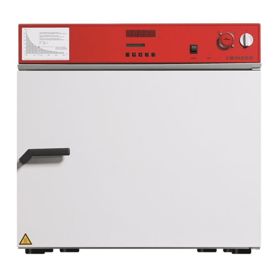
Page 18: Unit Overview
Unit overview Figure 4: Front view FDL 115 with optional window Control panel Microprocessor program controller RD3 Temperature safety device class 2 according to DIN 12880:2007 Main power switch ON/OFF Solvent curve Door handle Unit door Window (optional) FDL (E2) 03/2011 page 18/68... -
Page 19: Control Panel
Control panel (4) (3) (2) (2b) (2a) (1) RESET Figure 5: Control panel of standard unit Main power switch ON/OFF Temperature safety device class 2 (2a) Red pilot lamp for temperature safety device class 2 (2b) RESET key for temperature safety device Red indicator light, loss of technical ventilation RESET key for the heating cut-out due to failure of technical ventilation Temperature program controller RD3... -
Page 20: Completeness Of Delivery, Transportation, Storage, And Installation
Second-hand units are units that were used for a short time for tests or exhibitions. They are thoroughly tested before resale. BINDER ensures that the chamber is technically sound and will work flawlessly. Second-hand units are marked with a sticker on the unit door. Please remove the sticker before commis- sioning the unit. -
Page 21: Guidelines For Safe Lifting And Transportation
• Permissible ambient temperature range during transport: -10 °C / 14 °F to +60 °C / 140 °F. You can order transport packing and pallets for moving or shipping purposes from BINDER service. Storage Intermediate storage of the unit is possible in a closed and dry room. -
Page 22: Installation Of The Equipment
CAUTION Danger by stacking. Damage to the units. ∅ Do NOT place safety / paint drying ovens on top of each other. To completely separate the unit from the power supply, you must disconnect the power plug. Install the unit in a way that the power plug is easily accessible and can be easily pulled in case of danger. Do not install or operate the oven in potentially explosive areas. -
Page 23: Electrical Connection
Electrical connection The safety / paint drying oven FDL 115 is supplied ready for connection. • Power connection: fixed power connection cable 1800 mm / 5.9 ft in length with a shockproof plug • Power supply voltage 230 V (1N~) +/- 10 %, 50/60 Hz •... -
Page 24: Start Up
Start up After connecting the electrical supply (chap. 4.2), turn on the unit via the main power switch (1). Set the main power switch (1) to position “I”. Indicator light (3) and an audible signal indicate that the minimal volumetric flow rate of the technical ventilation has not yet been reached. Once the fan has reached its operating speed, indicator light (3) goes off. -
Page 25: General Indications
(setting in the user level, chap. 10). This setting is then valid for all program sections. Programming can be done directly via the controller keyboard or graphically at the computer using the software APT-COM™ 3 DataControlSystem (option, chap. 13.1) specially developed by BINDER. General indications... - Page 26 Program editor (chap. 8) • Two programs with up to 10 sections each or one program with up to 20 sections can be entered (se- lection in the user level, chap. 10). Entry of temperature set-points in all program sections (chap. 8.2). •...
-
Page 27: Fixed Value Entry Mode
Fixed value entry mode If you do not want to use the week program timer, deactivate it (factory setting, setting in the user level, chap. 10) before entering any set-points. Basic entry principle: Access the individual parameters with button X/W one after the other. Enter the values with the arrow keys. -
Page 28: Week Program Editor
Week program editor The Week program editor permits defining up to 4 shift point for each week day. A shift point defines a moment and the switching state ON or OFF of the channels that become active in this instance. Channel function: •... - Page 29 Display 1 shows 0000 Display 2 shows Shiftpt. (no function) Press program key Display 1 shows 0000 Display 2 shows Shiftpt. (selection of the shift point) (actual shift point: 1) Select the shift point (1 up to 4) with key Value is shown in display 2.
-
Page 30: Program Table Template For Week Program Editor
Program table template for Week program Editor Program editor Program title Project Date: Day of the week Time Channel 1 (tem- Channel 2* perature) hh:mm ON = SP2 OFF = SP1 Monday Tuesday Wednesday Thursday Friday Saturday Sunday * Channel 2 is non-functional in the standard unit FDL (E2) 03/2011 page 30/68... -
Page 31: Program Editor
Program editor Selecting between set-point ramp and set-point step You can program various kinds of temperature transitions. In the user level (chap. 10) you can select between the settings “Ramp” (default setting) and “Step”. Setting “Ramp” permits programming all kinds of temperature transitions. With setting “Step”... - Page 32 Program entry as set-point ramp (example): W/°C t/min. Program table corresponding to the diagram (with default setting “Ramp”): Section Temperature Section length set-point [hh.mm] [ °C] TEMP TIME 00:30 01:30 01:00 03:20 00:01 The values of such a program table can now be entered to the RD3 program controller (chap. 8.2). Program entry as set-point step (example): S01 S02 W/°C...
-
Page 33: Programming With Setting "Step
Program table corresponding to the diagram (with default setting “Ramp”): Section Temperature Section length set-point [hh.mm] [ °C] TEMP TIME 00:30 00:01 01:30 00:01 01:00 00:01 03:20 00:01 The values of such a program table can now be entered to the RD3 program controller (chap. 8.2). The end point of the desired cycle must be programmed with an additional section (in our examples S05 for set-point ramp and S08 for set-point step) with a section time of at least one minute. -
Page 34: General Notes On Programming Temperature Transitions
Program table corresponding to the diagram (with setting “Step”): Section Temperature Section length set-point [hh.mm] [ °C] TEMP TIME 00:30 01:30 01:00 03:20 The values of such a program table can now be entered to the RD3 program controller (chap. 8.2). 8.1.3 General notes on programming temperature transitions If the tolerance limits set in the user level (chap. - Page 35 – Step 1 Selecting the program and the program section: Normal Display Display 1 shows e.g. 39.8 (actual temperature value) Display 2 shows e.g. 15.01.07 13:52 - - (actual date and time, actual state of week program timer channel 1: Off, channel 2: Off) Press down key for 5 sec.
- Page 36 Next step – set-point entry in the desired program sections: Basic entry principle: Access the parameters of individual program sections with button X/W one after the other. Enter the values of the individual parameters with the arrow keys. A value flashing once after 2 seconds indicates that it has been adopted by the controller.
-
Page 37: Program Table Template
Program table template Program editor Program title Project Program No. Date: Section Temperature set-point Section length [ °C] [hh.mm] TEMP TIME FDL (E2) 03/2011 page 37/68... -
Page 38: Deleting A Program Section
Deleting a program section A program section is deleted from the program by setting the section duration to Zero. Normal display Press down key for 5 sec. Display 1 shows e.g. 0000 Display 2 shows PROGRAM EDITOR (you are in the program editor) Press program key Display 1 shows 0000... -
Page 39: Program Start Level
The following section (in our example now S03) is displayed: Display 1 shows e.g. 03 (actual selection of the section: S03) Display 2 shows P01:S03 (program section can be selected) alternating CONTINUE X/W (information: set-point entry with X/W) Press key EXIT or wait 120 sec Controller returns to Normal Display If you delete a program section which is followed by further sections, those following move up... - Page 40 Then define the settings for the program course. Two parameters can be set: • Program delay time, i.e. a defined time before a program starts. It can be entered with a precision of 1 minute, and its maximum value is 99.59 (99 hs 59 min). If the value is 00.00, the program will start immediately.
-
Page 41: User Level
During program course the arrow keys and the EXIT button are not functional. By pressing the program key for 3 seconds, you can terminate the program course. If you press button during program course, the entered set-point of the actually running program sec- tion is shown for 5 seconds: Display 1 shows e.g. - Page 42 • Counter of operating hours (Oper.hs) Information about the number of operating hours currently reached or since the last reset. (no setting, display only). • Max. number of operating hours (Op.limit) Enter a limit number of operating hours, i.e., the maximum number of operating hours that can be run. Maximum setting: 9999.
- Page 43 • Activating or inactivating the week program timer (Prog.Clk) „Inactive“: The week program timer is turned off (factory setting). The corresponding setting menu (chap. 7) is not visible, nor is set-point 2 in the “Fixed value entry mode” (chap. 6). „Active“: The week program timer is activated.
- Page 44 Normal Display Display 1 shows e.g. 19.8 (actual temperature value) Display 2 shows e.g. 15.05.06 13:52 - - (actual date and time, actual switching state of week pro- gram timer channel 1: Off, channel 2: Off) Press down key for 5 sec Display 1 shows e.g.
- Page 45 Press key Display 1 shows 0000 (no function) Display 2 shows Buzzer Active (setting of the alarm buzzer) (actual setting: „Active“) Select between “Active” and “Inactiv” using Setting is shown in display 2. arrow keys Press key Display 1 shows 0000 (no function) Display 2 shows Language :...
- Page 46 Press key Display 1 shows 0000 Display 2 shows PrgSelec: 2Prg10S (1 program with max. 20 sections or 2 programs with max. 10 sections each?) (actual setting: 2Prg10S) Select between “2Prg10S” and “1Prg20S” Setting is shown in display 2. using arrow keys Press key Display 1 shows 0000...
- Page 47 Press key Display 1 shows 0000 Display 2 shows Date (Main menu: Setting the date of the real time clock) Press program key Display 1 shows e.g. 2006 (Actual setting: 2006) Display 2 shows Year 2006 (Setting the year of the real time clock) Set year (2006 up to 2050) using arrow keys Setting is shown in display 2.
-
Page 48: Behavior In Case Of Failures
Behavior in case of failures 11.1 Behavior after power failure Power failure during fixed-value operation (Normal Display): the entered parameters remain saved. After power returns, operation continues with the set parameters. The heating starts operating after a delay time of 4 minutes. Power failure during program operation: After power return program course continues with the set- points that have been reached previously during program operation. - Page 49 When the safety device has turned off the unit, identifiable by the red alarm lamp (2a) lighting up, proceed as follows: • Disconnect the unit from the power supply. • Have the cause of the fault examined and rectified by a technician. •...
-
Page 50: Exhaust Air Monitoring
Options 13.1 Communication software APT-COM™ 3 DataControlSystem (option) The unit is regularly equipped with a serial interface RS 422 that can connect the BINDER communica- tion software APT-COM™ 3 DataControlSystem. The connection to a computer is established using the FDL interface via an interface converter RS 422 / RS 232. -
Page 51: Protocol Printer (Option)
13.2 Protocol printer (option) The protocol printer is connected using the FDL interface via an interface converter RS 422 / RS 232. Confirm that the interface mode is correctly set to “Printer” in the user level (chap. 10). Interface configuration: Baud rate: 9600 Stop bit:... -
Page 52: Additional Measuring Channel For Digital Object Temperature Indicator With Magnetic Sensor Or Pincer-Type Sensor (Option)
The object temperature data are put out together with the data of the temperature controller to the RS 422 interface as a second measuring channel and can be documented by the communication software APT-COM™ developed by BINDER (option, chap. 13.1). Socket... -
Page 53: Maintenance, Cleaning, And Service
Record the results of the maintenance tests in a service log Replace the door gasket only when cold. Otherwise, the door gasket may become damaged. We recommend taking out a maintenance agreement. Please consult BINDER Service. BINDER telephone hotline: +49 (0) 7462 2005 555... -
Page 54: Replacing The Intake Filter
14.2 Replacing the intake filter The fresh air intake filter (fine particle filter for particles 1µm up to 10 µm, class F6/EU6 acc. to EN 779:2002) at the top right-hand side must be replaced from time to time, depending on the degree of soiling. -
Page 55: Sending The Unit Back To Binder Gmbh
14.4 Sending the unit back to BINDER GmbH If you return a BINDER product to us for repair or any other reason, we will only accept the product upon presentation of an authorization number that has previously been issued to you. An authorization number will be issued after receiving your complaint either in writing or by telephone prior to your sending the BINDER product back to us. -
Page 56: Disposal
(Elektro- und Elektronikgerätegesetz, ElektroG) from 23 March 2005, BGBl. I p. 762 or contact BINDER service who will organize taking back and disposal of the unit according to the German national law for electrical and electronic equipment (Elektro- und Elektronik- gerätegesetz, ElektroG) from 23 March 2005, BGBl. -
Page 57: Disposal Of The Unit In The Member States Of The Ec Except For The Federal Republic Of Germany
Elektronikgerätegesetz, ElektroG) from 23 March 2005, BGBl. I p. 762. Instruct BINDER service to dispose of the device. The general terms of payment and delivery of the BINDER GmbH apply, which were valid at the time of purchasing the unit. - Page 58 If your distributor is not able to take back and dispose of the unit, please contact BINDER service. Certified companies disassemble waste (used) BINDER equipment in primary substances for recycling according to directive 2002/96/EC. The devices must be free from toxic, infectious or radioactive sub- stances in order to eliminate any health hazards to the employees of the recycling companies.
-
Page 59: Disposal Of The Unit In Non-Member States Of The Ec
CAUTION Alteration of the environment. For final decommissioning and disposal of the unit, please contact BINDER service. Follow the statutory regulations for appropriate, environmentally friendly disposal. The main board of the safety / paint drying oven includes a lithium cell. Please dispose of it according to national regulations. - Page 60 (chap. 10). (chap. 10). Only qualified service personnel authorized by BINDER must perform repair. Repaired units must comply with the BINDER quality standards. Every fire and explosion in relation to a lacquer dryer must be reported to the employer’s liabil- ity insurance association (for Germany).
-
Page 61: Technical Description
December 1996 by TÜV CERT). All test equipment used is subject to the administration of measurement and test equipment that is also constituent part of the BINDER QM DIN EN ISO 9001 sys- tems. They are controlled and calibrated to a DKD-Standard at regular intervals. - Page 62 77°F and a power supply voltage fluctuation of ±10. The temperature data is determined in accordance to BINDER factory standard following DIN 12880, observing the recommended wall clearances of 10 % of the height, width and depth of the inner chamber.
-
Page 63: Equipment And Options
17.4 Equipment and Options To operate the safety / paint drying oven, use only original BINDER accessories or accesso- ries / components from third-party suppliers authorized by BINDER. The user is responsible for any risk arising from using unauthorized accessories. -
Page 64: Spare Parts
17.5 Spare parts BINDER GmbH is responsible for the safety features of the unit only, provided skilled electri- cians or qualified personnel authorized by BINDER perform all maintenance and repair, and if components relating to chamber safety are replaced in the event of failure with original spare parts. -
Page 65: Dimensions Fdl 115
17.6 Dimensions FDL 115 ∅100 Figure 17: Dimensions FDL 115 FDL (E2) 03/2011 page 65/68... -
Page 66: Contamination Clearance Certificate
Contamination clearance certificate Unbedenklichkeitsbescheinigung Declaration regarding safety and health Erklärung zur Sicherheit and gesundheitlichen Unbedenklichkeit The German Ordinance on Hazardous Substances (GefStofV), and the regulations regarding safety at the workplace, require that this form be filled out for all products that are returned to us, so that the safety and the health of our employees can be guaranteed. - Page 67 Kind of transport / transporter / Transportweg/Spediteur: Transport by (means and name of transport company, etc.) Versendung durch (Name Spediteur o.ä.) ___________________________________________________________________________________ Date of dispatch to BINDER GmbH / Tag der Absendung an BINDER GmbH ___________________________________________________________________________________ FDL (E2) 03/2011 page 67/68...
- Page 68 We are aware that, in accordance with Article 823 of the German Civil Code (BGB), we are directly liable with regard to third parties, in this instance especially the employees of BINDER GmbH, who have been entrusted with the handling / repair of the unit / component. / Es ist uns bekannt, dass wir gegenüber Dritten –...
Need help?
Do you have a question about the APT.line FDL 115 and is the answer not in the manual?
Questions and answers