Table of Contents
Advertisement
Quick Links
Operating Manual
Translation of the original operating manual
VD (E3.1)
Vacuum Drying Oven
Standard: with RD4 microprocessor program controller
Optional: with MB2 microprocessor program controller
Model
VD 23
VD 23-UL
VD 56
VD 56-UL
VD 115
VD 115-UL
BINDER GmbH
Address: Post office box 102, 78502 Tuttlingen, Germany Phone: +49 7462 2005 0
Fax: +49 7462 2005 100 Internet: http://www.binder-world.com
E-mail: info@binder-world.com Service Hotline: +49 7462 2005 555
Service Fax: +49 7462 2005 93 555 Service E-Mail: service@binder-world.com
Service Hotline USA: +1 866 885 9794 or +1 631 224 4340 x3
Service Hotline Asia Pacific: +852 390 705 04 or +852 390 705 03
Service Hotline Russia and CIS: +7 495 988 15 16
Issue 03/2020
Model version
VD023-230V
VD023UL-120V
VD056-230V
VD056UL-120V
VD115-230V
VD115UL-120V
Art. No.
9630-0001
9630-0005
9630-0002
9630-0006
9630-0003
9630-0007
Art. No. 7001-0383
Advertisement
Table of Contents

Subscribe to Our Youtube Channel
Related Manuals for Binder VD Series


Summary of Contents for Binder VD Series
- Page 1 Fax: +49 7462 2005 100 Internet: http://www.binder-world.com E-mail: info@binder-world.com Service Hotline: +49 7462 2005 555 Service Fax: +49 7462 2005 93 555 Service E-Mail: service@binder-world.com Service Hotline USA: +1 866 885 9794 or +1 631 224 4340 x3 ...
-
Page 2: Table Of Contents
Contents SAFETY ........................8 Personnel Qualification ........................8 Operating manual ..........................8 Legal considerations ........................... 8 Structure of the safety instructions ...................... 9 1.4.1 Signal word panel ........................9 1.4.2 Safety alert symbol ........................9 1.4.3 Pictograms ..........................10 1.4.4 Word message panel structure .................... - Page 3 Performance during and after power failures ..................43 5.3.1 RD4 controller ......................... 43 5.3.2 MB2 controller ......................... 44 START UP ......................44 Condition after establishing the power connection ................44 Standby mode Turning on and off the vacuum drying oven ............. 45 6.2.1 RD4 controller .........................
- Page 4 MB2 controller ........................... 66 9.2.1 User management, authorization levels and password protection ......... 66 9.2.2 Log in ............................69 9.2.3 Log out ............................ 70 9.2.4 User change ..........................70 9.2.5 Password assignment and password change ................ 71 9.2.5.1 Password change ......................71 9.2.5.2 Deleting the password for an individual authorization level ..........
- Page 5 13. NOTIFICATION AND ALARM FUNCTIONS ............93 13.1 Information messages ........................93 13.1.1 RD4 controller ......................... 93 13.1.2 MB2 controller ......................... 94 13.2 Alarm messages ..........................95 13.2.1 RD4 controller ......................... 95 13.2.2 MB2 controller ......................... 96 13.3 Resetting an alarm ..........................97 13.3.1 RD4 controller .........................
- Page 6 16.6.3 Start time ..........................121 16.6.4 Setpoint entry ........................121 16.6.5 Special controller functions ....................122 17. NETWORK AND COMMUNICATION ..............122 17.1 RD4 controller: Ethernet network settings ..................122 17.1.1 Showing the network settings ....................122 17.1.1.1 Showing the chamber‘s MAC address ................122 17.1.1.2 Showing the IP address....................
- Page 7 24.4.1 RD4 controller ........................150 24.4.2 MB2 controller ........................151 24.5 Sending the chamber back to BINDER GmbH ................151 25. DISPOSAL......................152 25.1 Disposal of the transport packing ....................152 25.2 Decommissioning ..........................152 25.3 Disposal of the chamber in the Federal Republic of Germany ............153 25.4 Disposal of the chamber in the member states of the EU except for the Federal Republic of...
-
Page 8: Safety
In no event shall BINDER be held liable for any damages, direct or incidental arising out of or related to the use of this manual. -
Page 9: Structure Of The Safety Instructions
All obligations on the part of BINDER derive from the respective purchase contract, which also contains the entire and exclusively valid statement of warranty administration and the general terms and conditions, as well as the legal regulations valid at the time the contract is concluded. -
Page 10: Pictograms
1.4.3 Pictograms Warning signs Stability hazard Explosive atmosphere Electrical hazard Hot surface Harmful substances Inhalation hazard Suffocation hazard Lifting hazard Pollution Hazard Biohazard Risk of corrosion and / or chemical burns Mandatory action signs Disconnect the power Lift with several persons Mandatory regulation Read operating plug... -
Page 11: Localization / Position Of Safety Labels On The Chamber
Keep safety labels complete and legible. Replace safety labels that are no longer Figure 1: Position of labels on the chamber (example: legible. Contact BINDER Service for these regular chamber with RD4 controller) replacements. Type plate The type plate sticks to the left side of the chamber, bottom right-hand. -
Page 12: General Safety Instructions On Installing And Operating The Chamber
213-850 on safe working in laboratories, issued by the employers’ liability insurance association (for Germany). BINDER GmbH is only responsible for the safety features of the chamber provided skilled electricians or qualified personnel authorized by BINDER perform all maintenance and repair, and if components relating to chamber safety are replaced in the event of failure with original spare parts. - Page 13 The chamber does not dispose of any measures of explosion protection. DANGER Danger of explosion due to introduction of flammable or explosive substances in the chamber. Serious injury or death from burns and / or explosion pressure. ∅ Do NOT introduce any substance into the chamber which is combustible or explosive at working temperature.
-
Page 14: Intended Use
Such ingredients include in particular acids and halides. Any corrosive damage caused by such ingredients is excluded from liability by BINDER GmbH. The chamber does not dispose of any measures of explosion protection. -
Page 15: Foreseeable Misuse
Medical devices The chambers are not classified as medical devices as defined by the Medical Device Directive 93/42/EEC. Due to the special demands of the Medical Device Directive (MDD), these chambers are not qualified for sterilization of medical devices as defined by the directive 93/42/EWG. Personnel Requirements Only trained personnel with knowledge of the Operating Manual can set up and install the chamber, start it up, operate, clean, and take it out of operation. -
Page 16: Residual Risks
To prevent these and other risks from incorrect operation, the operator shall issue operating instructions. Standard operating procedures (SOPs) are recommended. 1.10 Residual Risks The unavoidable design features of a chamber, as well as its proper field of application, can also pose risks, even during correct operation. -
Page 17: Operating Instructions
• Absence of a plausibility check to rule out erroneous inscription of electrical components • Performance of repair work by untrained/insufficiently qualified personnel • Inappropriate repairs which do not meet the quality standard specified by BINDER • Use of replacement parts other than BINDER original replacement parts •... - Page 18 • Floors See operating manual chap. 3.4 for correct installation • Cleaning See operating manual chap. 23.3. VD (E3.1) 03/2020 page 18/173...
-
Page 19: Description Of The Equipment
The chamber comes equipped with an Ethernet serial interface for computer communication and with a USB interface. In addition, the BINDER APT-COM™ 4 Multi Management Software permits networking up to 100 chambers and connecting them to a PC for controlling and programming, as well as recording and representing temperature and pressure data. -
Page 20: Chamber Overview
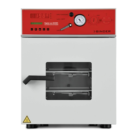
Chamber overview Figure 3: VD 115 with RD4 controller Figure 4: VD 115 with optional MB2 controller Triangular instrument panel with chamber controller Chamber door Door handle Elastic-mounted safety glass window VD (E3.1) 03/2020 page 20/173... -
Page 21: Instrument Panel With Regular Rd4 Controller
Instrument panel with regular RD4 controller RD4 controller display USB interface Figure 5: Instrument panel with RD4 controller and USB interface Instrument panel with optional MB2 controller 5,7" controller display with touchscreen USB interface Pilot lamp Figure 6: Instrument panel with MB2 program controller and USB interface Connections on the rear of the chamber Rear control panel (1a) - Page 22 (1) (2) (3) (5) (9) (10) (11) VD 23 (1) (2) (3) (10) (11) VD 56 (10) (11) VD 115 (6) (7) Figure 8: Rear control panel VD (230 V) with options Connection for IEC connector plug 230 V AC for VD Connection for IEC connector plug 100-120 V AC for VD -UL Miniature fuses 250 V AC (T): 2x 6,3 A for VD 23, 2x 8 A for VD 56, 2x 10 A for VD 115, 1x 10 A for VD 23-UL, 2x 16 A for VD 56-UL, 2x 20 A for VD 115-UL...
-
Page 23: Completeness Of Delivery, Transportation, Storage, And Installation
Note on second-hand chambers (Ex-Demo-Units): Second-hand chambers are chambers that were used for a short time for tests or exhibitions. They are thoroughly tested before resale. BINDER ensures that the chamber is technically sound and will work flawlessly. Second-hand chambers are marked with a sticker on the chamber door. Please remove the sticker before commissioning the chamber. -
Page 24: Guidelines For Safe Lifting And Transportation
Lift chambers size 115 with the aid of 6 people. • Permissible ambient temperature range during transport: -10 °C / 14°F to +60 °C / 140°F. You can order transport packing for moving or shipping purposes from BINDER Service. Storage Intermediate storage of the chamber in a closed and dry room. - Page 25 The maximum permissible ambient temperature of the vacuum pumps supplied by BINDER is 40 °C / 104 °F.
-
Page 26: Installation And Connections
DANGER Suffocation hazard due to high concentration of inert gas. Death by suffocation. ∅ Do NOT set up chambers in non-ventilated recesses. Make sure that technical ventilation measures are active. Respect the relevant regulations for handling inert gases. ... -
Page 27: Pump Module (Option)
Pump module (option) The mounting instructions Art. no. 7001-0137 supplied with the pump module describe how to mount the VD vacuum drying oven onto the pump module and installing the suction line into the pump module. (13) Vorderansicht Rückansicht Figure 10: VD mounted on pump module (example: size 115) (14) (14) (13) -
Page 28: Pump Module Without Pump (Option)
When using a vacuum hose, we recommend using the BINDER connection kit VD Art. no. 8012-0146 (chap. 4.3.1. The pump module has an appropriate hose outlet at the back. - Page 29 The connection is established via PIN 6 and PIN 7. A 1.2 m cable with fitting plugs is enclosed. Figure 13: Pin configuration of the SUB-D socket “Pump module” (8) to switch on/off the pump module socket Installation of the supplied vacuum pump •...
-
Page 30: Vacuum Connection
Vacuum pumps supplied by BINDER are designed for a gas inlet temperature of von max. 40 °C / 104°F. Observe the permitted gas inlet temperature. The following values refer to the maximum ambient temperature of the pump of 40 °C / 104 °F. -
Page 31: Connecting Inert Gas Supply
Connecting inert gas supply When operating the VD vacuum drying oven with inert gas, correctly follow the technical ventilation measures, as described in the DGUV guidelines 213-850 on safe working in laboratories, issued by the employers’ liability insurance association (for Germany). When operating with inert gas, the chamber is supplied with an oxygen displacing gas, e.g., N . -
Page 32: Electrical Connection
• After connecting the power cable to connection (1), lead it through the strain relief (1a). • Only use original connection cables from BINDER • Pollution degree (acc. to IEC 61010-1): 2 • Over-voltage category (acc. to IEC 61010-1): II See also electrical data (chap. -
Page 33: Functional Overview And Menu Structure Of The Controller
You can enter the desired set point values in the “Set points” menu directly at the controller or use the APT-COM™ 4 Multi Management Software (option) specially developed by BINDER. The controller offers various notifications and alarm messages with visual and audible indication. All controller setting remain valid until the next manual change. -
Page 34: Menu Structure Of The Controller And Access Levels
• Admin: The password enables access to advanced controller functions and settings. Factory setting is 00 01. • Service: The password enables access to all controller functions (for BINDER Service only). As soon as a password has been assigned, access to the respective functions is blocked and only available after entering the correct password. -
Page 35: Mb2 Controller
Menu Required access level Functions • Configuration settings (only for BINDER Service) Service “Service” • Password changing for User and Admin • Export of configuration, logger, and service data Export: Any user • Import of configuration data Import: “Admin” Unless noted otherwise, the figure in this manual show the functional range, which is available for the user with “Admin”... -
Page 36: Operating Functions In Normal Display
5.2.1 Operating functions in normal display Current operating mode Text list for information icons Date, time, authorization level of the logged-in user, memory Quick setpoint entry Continue to next screen Back to Normal display Information Program start Setpoint entry Event list Display of active alarms Access to main menu Figure 17: Operating functions of the MB2 controller in normal display (example values) -
Page 37: Display Views: Normal Display, Program Display, Chart-Recorder Display
5.2.2 Display views: Normal display, program display, chart-recorder display Press the Change view icon to toggle between normal display, program display and chart- recorder display. Press the Normal display icon to return from program display and chart recorder display back to Normal display. -
Page 38: Mb2 Controller Icons Overview
5.2.3 MB2 controller icons overview Navigation icons in Normal display Icon Signification Function Main menu Access from Normal display to the main menu Alarm Access from Normal display to the list of active alarms Event list Access from Normal display to the event list Access from Normal display to the setpoint entry menu: setpoint Setpoint setting entry for Fixed value operation, turning on/off temperature and/or... - Page 39 Functional icons in the chart recorder display Icon Signification Function Show legend Show legend Hide legend Hide legend Pause chart recorder and change to history display. Data recording History display continues. Curve selection Go to “Curve selection” submenu in the history display Go to “Search”...
-
Page 40: Mb2 Controller Operating Modes
5.2.4 MB2 controller operating modes The MB2 program controller operates in the following operating modes: • Fixed value operating mode The controller operates as a fixed-point controller, i.e., set-points for temperature and pressure can be defined, which are then maintained until the next manual change (chap. 7.2.1). •... -
Page 41: Main Menu
• Access to service data, controller reset to factory settings (chap. 5.2.5.3) • Available only for users with “Service” and “Admin” authorization level. Full functional range only for BINDER Service (users with “Service” authorization level). “Programs” submenu • Access to the controller’s program functions (chap. 14, 15, 16) •... -
Page 42: Settings" Submenu
5.2.5.3 “Service” submenu The “Service” submenu is available for users with “Service” or “Admin” authorization level. When logged- in with “Admin” authorization level the user will find information to tell the BINDER Service in service case. Main menu > Service... -
Page 43: Principle Of Controller Entries
5.2.6 Principle of controller entries In the selection and entry menus there are icons displayed in the footers which you can use to take over the entry or cancel it. Selection menu (example) Entry menu (example) After completing the settings there are the following possibilities: Press the Confirm icon to take over the entries and exit the menu or continue the menu sequence. -
Page 44: Mb2 Controller
5.3.2 MB2 controller After the power returns, the controller continues to function in the original operating mode it was in previously before the power failure occurred: • Performance after power failure in Fixed value operation mode All functions return to the same status the chamber had before power failure. The set-points are immediately resumed. -
Page 45: Standby Mode Turning On And Off The Vacuum Drying Oven
Standby mode Turning on and off the vacuum drying oven To completely separate the chamber from the power supply, you must disconnect the power plug. For decommissioning observe the guidelines in chap. 24.2. All settings and setpoint values are saved after turning off the chamber. 6.2.1 RD4 controller Deactivating the Standby mode (turning on the chamber): After establishing power supply, press down the Standby button for 5 seconds to turn on the chamber. -
Page 46: Controller Settings Upon Start Up
Deactivating the Standby mode (turning on the chamber To deactivate the „Standby“ function, unmark the checkbox. Controller settings upon start up Depending on the functions activated in the controller, various settings can be requested directly after turning on the chamber. Then you should assign a password for the operating level (chap. -
Page 47: Vacuum System
Locked operation Provided that the user administration has been activated by the assignment of passwords for the different authorization types, the controller operation is first locked after turning on the unit, recognizable by the closed lock icon in the header. In the locked view the controller provides all display functions. -
Page 48: Ventilation After Completing The Drying Procedure (Flooding With Ambient Air Or Inert Gas)
6.4.2 Ventilation after completing the drying procedure (flooding with ambient air or inert gas) The duration of the drying procedure can be determined via the pressure display on the controller. When the decreasing pressure reaches the set-point value, the drying process is completed. If the drying monitoring (section 12.7) is activated, a corresponding message is displayed. -
Page 49: Set-Point Entry
Install a pressure reducer for inert gas operation. Set the pressure reducer to a pressure slightly above ambient pressure. Ensure that the pressure reducer will open. Do not change this setting in order to avoid perturbation inside the oven and release of big quantities of inert gas after flooding the VD. For ventilation an inert gas, e.g., nitrogen, is led into the inner chamber via the connection (4) or the optional connection (5), until pressure compensation with the atmosphere occurs. -
Page 50: Pressure Set-Point Entry
7.1.2 Pressure set-point entry Required access level: “User”. Path: Normal display Setpoints Pressure Press the OK button to enable the setting. Pressure setting The current setting flashes. Enter the desired set-point with the arrow buttons. Confirm the entry with the OK button. Pressure (mbar) With the arrow-up button you can go back to the temperature set-point entry (chap. -
Page 51: Direct Setpoint Entry Via Normal Display
“Setpoints” menu. Select “Fixed value operation setpoints” to access the individual parameters. • Select the field “Temperature” and enter the desired temperature setpoint. Confirm entry with Confirm icon. • Select the field “Pressure” and enter the desired pressure setpoint. Confirm entry with Confirm icon. When entering a value outside the setting range, the message: “Value outside of limits! (Min: xxx, Max: xxx)”... -
Page 52: Setting Special Controller Functions
Setting special controller functions You can set the following functions via the controller menu: • Activate / deactivate the Standby mode (chap. 6.2) • Turning off the vacuum pump via the socket on the pump module (chap. 8.2) • Use the optional connection “GAS/AIR2” (10) for ventilation (chap. 8.3) •... -
Page 53: Quick Access Menu
Example: Normal display with activated function 1 “Standby” T / pressure (mbar) 8.1.1.2 Quick Access menu More functions are available via the Quick Access menu: Path: Normal display Pressure control • Function “Temperature control” (chap. 8.5) • Function “Pressure control” (chap. 8.6) •... - Page 54 Setpoint > Fixed value operation setpoints > Functions on/off Path: • Function “Standby” (chap. 6.2) • Function “GAS/AIR 2” (chap. 8.3) • Function “Close all valves” (chap. 8.4) • Function “Vacuum pump off” (chap. 8.2) “Setpoints” menu. “Functions on/off” entry menu. Select the field “Functions on/off”.
-
Page 55: Control On/Off" Menu
8.1.2.2 “Control on/off” menu More functions are available via the “Control on/off” menu. Press the Setpoint setting icon to access the “Setpoint” setting menu from Normal display.. Setpoint > Control on/off Path: • Function “Temperature” (temperature control, chap. 8.5) • Function “Pressure” (pressure control,chap. 8.6) “Setpoints”... -
Page 56: Mb2 Controller
8.2.2 MB2 controller Press the Setpoint setting icon to access the “Setpoint” setting menu from Normal display.. Setpoint > Fixed value operation setpoints > Functions on/off Path: “Functions on/off” menu. Mark the checkbox of the function “Vacuum pump off” to activate it and press the Confirm icon. -
Page 57: Rd4 Controller
8.3.1 RD4 controller Path: Normal display Setpoints Functions on/off GAS/AIR 2 Press the OK button to access the function “GAS/AIR 2”. Function 2 “GAS/AIR 2”. The current switching state is shown (example). GAS/AIR 2 Press the OK button to enable the setting. Setting the function 2 “GAS/AIR 2”. -
Page 58: Close All Valves
Close all valves Close all existing fine dosing valves 8.4.1 RD4 controller Path: Normal display Setpoints Functions on/off Close all valves Press the OK button to access the function “Close all valves”. Function 3 “Close all valves”. The current switching state is shown (example). Close all valves Press the OK button to enable the setting. -
Page 59: Activating / Deactivating Temperature Control
Activating / deactivating temperature control 8.5.1 RD4 controller Path: Normal display Temperature control Press the OK button to enable the setting. Setting the “Temperature control” function. Use the arrow buttons to select between “On” (temperature control active) and “Off” (temperature control deactivated). Confirm the setting with the OK button. -
Page 60: Activating / Deactivating Pressure Control
The actual temperature value continues to be displayed in Normal display: Normal display with deactivated temperature control. Activating / deactivating pressure control When operating the chamber without a vacuum connection, you can deactivate pressure control with the to avoid alarms of the pressure system. No pressure tolerance range alarms and no pressure alarm will be emitted. -
Page 61: Mb2 Controller
8.6.2 MB2 controller Press the Setpoint setting icon to access the “Setpoint” setting menu from Normal display.. Setpoint > Control on/off Path: “Setpoints” menu. Select the field “Control on/off” (example: deactivated pressure control). Mark / unmark the “Pressure” checkbox to activate / deactivate pressure control and press the Confirm icon •... -
Page 62: Drying Monitoring
Drying monitoring Pressure Time Figure 18: Schematic timing of the drying process and drying monitoring Procedure: • Enter the temperature set-point. The previously entered pressure setpoint is not used with this function. It remains saved. The drying monitoring uses a fixed minimum pressure setpoint. -
Page 63: Rd4 Controller
8.7.1 RD4 controller Path: Normal display Drying monitoring Press the OK button to enable the setting. Setting the function “Drying monitoring”. Use the arrow buttons to select between “Start” (start drying monitoring) and “Cancel” (terminate drying monitoring). Confirm the setting with the OK button. Start After confirming with the OK button or with the Back button you go back to Normal... -
Page 64: Authorization Levels And Password Protection
Authorization levels and password protection RD4 controller 9.1.1 Password request To access menus for which access is restricted, you must enter the corresponding password. After calling the appropriate menu function with the OK button the password request appears. Password request. The left two digits are flashing. -
Page 65: Assign And Modify The Admin Password
Setting the User password. The right two digits are flashing. Enter the desired numbers with the arrow buttons. Confirm the setting with the OK button. Password User With the arrow-down button you can now proceed to enter the Admin password. With the Back button you can go back to the “Chamber”... -
Page 66: Mb2 Controller
• All passwords can be changed in the “log out” submenu (chap. 9.2.3). “Service” authorization level • Authorization level only for BINDER service • Extensive authorization for controller operation and configuration, access to service data • The passwords for “Service”, “Admin” and “User” authorization levels can be changed in the “log out”... - Page 67 Operation after user login At user login, the authorization level is selected and confirmed by entering the respective password. Following user login, controller operation is available, recognizable by the open-lock icon in the header. The available controller functions correspond to the user’s authorization level. Password protection activated for all levels: operation without user login is locked If passwords have been assigned for all authorization levels, the controller is locked without...
- Page 68 Information window To check the authorization level of the user currently logged-in, select in Normal display the arrow far right in the display header. The information window shows date and time, the controller’s free memory space and under “Authorization” the authorization level of the current user. If passwords have been assigned for all authorization levels, a user without login (password entry) has no authorization.
-
Page 69: Log In
9.2.2 Log in Main menu > User > Log in Path: Controller without a user logged-in Selection of user type (example) All selection possibilities are password protected Controller with logged-in user After completing the settings, press the Confirm icon to take over the entries and exit the menu, or press the Close icon to exit the menu without taking over the entries. -
Page 70: Log Out
9.2.3 Log out Main menu > User > Log out Path: Controller with Controller logged-in user without a user (e.g. “Admin” logged-in authorization) 9.2.4 User change If the password function has been deactivated (chap.9.2.5.2) this function is not available. Main menu > User > User change Path: Controller with logged-in user... -
Page 71: Password Assignment And Password Change
9.2.5 Password assignment and password change This function is not available for a user logged-in with “User” authorization. 9.2.5.1 Password change A logged-in user can change the passwords of his current level and of the next lower level(s). Example: A user with “Admin” authorization can change the passwords for the “Admin” and “User” authorization levels. - Page 72 In the “Keyboard switch” window you can select different keyboards to enter uppercase and lowercase letters, digits, and special characters. All types of characters can be combined within one single password. Example: access the digit entry window Entry of digits To confirm the entry, press the Confirm icon.
-
Page 73: Deleting The Password For An Individual Authorization Level
9.2.5.2 Deleting the password for an individual authorization level A user logged-in with “Service” or “Admin” authorization can delete the passwords of his current level and of the next lower level(s). To do this no password is entered during a password change. Main menu >... -
Page 74: New Password Assignment For "Service" Or "Admin" Authorization Level When The Password Function Was Deactivated
9.2.5.3 New password assignment for “service” or “admin” authorization level when the password function was deactivated If the password protection for an authorization level has been deactivated, i.e., no password is assigned, no login for this level is possible. Therefore access to this authorization level is available without login. If the password for the “Service”... -
Page 75: Activation Code
9.2.6 Activation code Certain functions of the controller can be unlocked with a previously generated activation code. The activation code enables access to functions available only in the “Service” authorization level by users without a “Service” authorization. Such functions include e.g., adjustment or extended configurations. -
Page 76: General Controller Settings And Information
General controller settings and information 10.1 RD4 controller The general settings can be accessed in the “Settings” submenu, which is available for users with “Service” or “Admin” authorization level. It serves to enter date and time, select the language for the controller menus and the desired temperature unit and to configure the controller’s communication functions. -
Page 77: Setting The Current Date
With the Back button you can go back to the “Chamber” submenu and, repeatedly pressing it, to Normal display. 10.1.3 Setting the current date Required access level: “Admin”. Following start-up of the chamber (chap. 6.2.1), it is “User”. Path: Normal display Settings Chamber Date... -
Page 78: Setting The Current Time
10.1.4 Setting the current time Required access level: “Admin”. Following start-up of the chamber (chap. 6.2.1), it is “User”. Path: Normal display Settings Chamber Time Press the OK button to enable the setting. Setting the time: hours The current setting flashes. Enter the current hour with the arrow buttons. -
Page 79: Setting The Chamber Address
10.1.6 Setting the chamber address This setting is required for the communication with the BINDER APT-COM™ 4 Multi Management Software. The chamber address settings in the chamber controller and in the software must be identical. Required access level: “Admin”. Path:... -
Page 80: Mb2 Controller
10.2 MB2 controller Most of the general settings can be accessed in the “Settings” submenu, which is available for users with “Service” or “Admin” authorization level. It serves to enter date and time, select the language for the controller menus and the desired temperature unit and to configure the controller’s communication functions. - Page 81 Or later: Main menu > Settings > Date and time Path: “Date and time” submenu. “Date / time” entry menu. Select the field “Date / time”. Enter date and time and press the Confirm icon. “Date and time” submenu. “Date and time” submenu. In the field “Daylight saving time switch”...
-
Page 82: Selecting The Temperature Unit
10.2.3 Selecting the temperature unit Following start-up of the chamber: Or later: Main menu > Settings > Chamber Path: Select the desired temperature unit and press the Confirm icon. Change of the temperature unit between °C and °F. If the unit is changed, all values are converted accordingly C = degree Celsius 0 °C = 31°F... -
Page 83: Touchscreen Calibration
• Select the field “Brightness”. Move the grey slide to the left or right to define the brightness of the display • left = darker (minimum value: 0) • right = brighter (maximum value: 100) Press the Confirm icon. • Select the field “Wait time for screen saver” and enter the desired waiting time for the screen saver in seconds. -
Page 84: Event List
The waiting icon shows how much time there is left to touch the currently activated box. If the box is not touched withing this period, calibration is aborted and the display changes to Normal display. After completing the calibration, i.e., touching all four boxes, the display changes to Normal display. 10.2.5 Event list The “Event list”... -
Page 85: Current Operating Parameters
• Select “Safety controller” to see information on the safety controller status. 10.2.8 Technical chamber information Main menu > Device info Path: Chamber name and setup Versions of CPU, I/O module and safety for BINDER controller Service Information on digital and analog inputs and for BINDER outputs and phase angle outputs... -
Page 86: Temperature Safety Devices
Temperature safety devices 11.1 Over temperature protective device class 2 (thermal switch) The chamber is equipped with an internal temperature safety device class 2.0 acc. to DIN 12880:2007. It serves to protect the chamber and prevent dangerous conditions caused by major defects of the chamber. -
Page 87: Setting The Safety Controller
• Offset: Offset value, maximum overtemperature above any active temperature set point. The resulting maximum temperature changes internally and automatically with every temperature set-point change. MB2 controller: This setting is recommended for program operation. It is important to check the safety controller set-point and safety controller mode occasionally, as it does not offer a fix, independent limit temperature value, which would never be exceeded. -
Page 88: Mb2 Controller
Setting the safety controller value with “Offset” safety controller mode The current value flashes. Enter the desired offset value with the arrow buttons. Confirm the entry with the OK button. Offset With the Back button you can go back to the “Safety controller”... -
Page 89: Message And Measures In The State Of Alarm
11.2.3 Message and measures in the state of alarm 11.2.3.1 RD4 controller The state of alarm is indicated visually in Normal display. If the buzzer is enabled (chap. 13.4.1) there is an additional audible alert. The heating turns off. As soon as the inner chamber temperature has cooled down below the safety controller value, the heating can be is released. -
Page 90: Function Check
11.2.4 Function check Check the safety controller at appropriate intervals for its functionality. It is recommended that the authorized operating personnel should perform such a check, e.g., before starting a longer work procedure. Tolerance range settings In this menu you can define for temperature and pressure the deviation between the actual value and setpoint, which that shall cause a tolerance range alarm. -
Page 91: Setting The Delay Time For Pressure Tolerance Range Alarm
With the arrow-down button you can now change to setting the delay for pressure tolerance range alarm. With the Back button you can go back to the “Various” submenu and, repeatedly pressing it, to Normal display. 12.1.3 Setting the delay time for pressure tolerance range alarm Path: Normal display Settings... -
Page 92: Mb2 Controller
12.2 MB2 controller 12.2.1 Setting the alarm delay times and the tolerance ranges Main menu > Settings > Various Path: Submenu “Various”. • Select the field “Temp. alarm delay” and enter the time in minutes, after which the temperature range alarm shall be triggered. -
Page 93: Notification And Alarm Functions
Notification and alarm functions 13.1 Information messages 13.1.1 RD4 controller Information messages provide information about the settings made or the current controller condition. In Normal display a text message indicates the condition. The “Information” icon is flashing slowly. Information message (example: Pressure control deactivated) T / pressure (mbar) Pressure control off... -
Page 94: Mb2 Controller
13.1.2 MB2 controller Information messages are indicated by information icons displayed in the screen header in Normal display An information icon serves as an indication of a certain condition. If this condition persists, in some cases an alarm will be triggered after a fix or configurable interval. As long as the condition persists, the information icon therefore continues to be displayed also in state of alarm. -
Page 95: Alarm Messages
13.2 Alarm messages 13.2.1 RD4 controller In the event of equipment failures, when the temperature and / or pressure deviate from the set tolerance range limits, optical and possibly acoustic alarm messages are given out via the controller. The alarm messages on leaving the tolerance range are emitted after a configurable delay (chap. 12.1.1, 12.1.2), the others immediately when the fault occurs. -
Page 96: Mb2 Controller
13.2.2 MB2 controller Alarm messages overview: Start after Condition Alarm message condition occurred The current actual temperature value after configurable time is outside the tolerance range (chap. “Temperature range” (chap. 12.2.1) Factory setting: 10 minutes after configurable time The current actual pressure value is “Pressure range (chap. -
Page 97: Resetting An Alarm
13.3 Resetting an alarm 13.3.1 RD4 controller Press the OK button to confirm the alarm. • Confirmation while the state of alarm persists: Only the buzzer is muted. The visual alarm message continues to be displayed until the alarm condition is removed. Then it is reset automatically. •... -
Page 98: Activating / Deactivating The Audible Alarm (Buzzer)
13.4 Activating / deactivating the audible alarm (buzzer) 13.4.1 RD4 controller Path: Normal display Settings Chamber Audible alarm Press the OK button to enable the setting. Setting the audible alarm. The current setting flashes. Use the arrow buttons to select between ON and OFF. -
Page 99: Mb2 Controller: Timer Program (Stopwatch Function)
MB2 controller: Timer program (stopwatch function) During an entered duration the controller constantly equilibrates to the setpoints entered in Fixed value operation mode (temperature, pressure, configuration of the special controller functions). This duration can be entered as a “Timer program”. During the program runtime, any setpoint changes do not become effective;... -
Page 100: Stopping A Running Timer Program
14.2 Stopping a running timer program 14.2.1 Pausing a running timer program Press the Program pause icon to interrupt the program. The program is paused. The program runtime stops running down, the time display flashes. There are the following options: Press the Program start icon to continue the program Press the Cancelling icon to cancel the program 14.2.2 Cancelling a running timer program... -
Page 101: Mb2 Controller: Time Programs
MB2 controller: Time programs The MB2 program controller permits programming time programs with real-time reference. It offers 25 program memory positions with up to 100 program sections each. For each program section you can enter a temperature set-point, a pressure set-point, section duration, type of temperature and pressure transition (ramp or step), the switchings states of the special controller functions and the tolerance ranges. -
Page 102: Performance During Program Delay Time
15.1.1 Performance during program delay time During the configured program delay time until program start, the controller equilibrates to the current setpoints of Fixed value operation mode. Modifications of these setpoints are effective. When the configured moment for program start is reached, the program delay time ends and the program starts running. -
Page 103: Creating A New Time Program
15.4 Creating a new time program Main menu > Programs > Time program Path: Enter the program name and, if desired, “Time program” menu: additional program information in the overview of the existing programs. corresponding fields. Select an empty program place. Press the Confirm icon. -
Page 104: Deleting A Time Program
Program editor: “Edit program” menu Select the desired function and press the Confirm icon. The program editor offers following options: • Change the program name • Copy program • Replace program: Replacing an new or an existing program with the copied program. This menu point is visible only after a program has been copied. -
Page 105: Section Editor: Section Management
15.6 Section editor: section management Main menu > Programs > Time program Path: Select the desired program. Program view. Section view (example: section 1). Select the desired program section There are the following options: (example: section 1) ... -
Page 106: Add A New Program Section
15.6.1 Add a new program section Section editor: “Edit section” menu. Select “Create new section” and press the Confirm icon. Then select whether to insert the new section before or after the current section. Press the Confirm icon. The new section opens. 15.6.2 Copy and insert or replace a program section Program view. -
Page 107: Deleting A Program Section
Press the Edit icon to open the section editor if you want the current section to be replaced or the copied section to be inserted before or after it Program view. Section view (example: section 1). Select the section to be replaced or before or Press the Edit icon to open the section editor after which the copied section shall be inserted (example: section 2) and press the... -
Page 108: Value Entry For A Program Section
15.7 Value entry for a program section Main menu > Programs > Time program Path: Select the desired program and section. The section view gives access to all parameters of a program section. You can enter or modify the values. Program name and section number Section duration Type of setpoint transition: ramp or step... -
Page 109: Set-Point Ramp And Set-Point Step
15.7.2 Set-point ramp and set-point step You can define the type of temperature and pressure transitions for each individual program section. “Ramp” mode: Gradual changes of temperature and pressure The set-point of a given program section functions as the section’s start temperature. During the section’s duration, the set-point gradually passes to the set-point of the subsequent program section. -
Page 110: Special Controller Functions
“Ramp” and “Step” mode example (representation of a temperature course) W/°C t/min. Corresponding program table Duration Temperature Pressure Section No. Ramp or Step [hh:mm:ss] [°C] mbar] 00:10:00 40.0 xxxx Step 00:20:00 60.0 xxxx Step 00:10:00 80.0 xxxx Step 00:20:00 40.0 xxxx Step 00:10:00... -
Page 111: Setpoint Entry
Section view indicating the controller functions. The functions are displayed from right to left. Activated function: switching status “1” (On) Deactivated function: switching status “0” (Off) Example: Activated function “Standby” = 000000000000000 Deactivated function “Standby” = 000000000000000 15.7.4 Setpoint entry •... -
Page 112: Repeating One Or Several Sections Within A Time Program
Section view, showing the temperature tolerance range • Select the field “Tolerance band min” and enter the desired lower tolerance band value. Setting range: -99999 to 99999. Confirm entry with Confirm icon. The controller returns to the section view. • Select the field “Tolerance band max” and enter the desired upper tolerance band value. Setting range: -99999 to 99999. -
Page 113: Saving The Time Program
• Select the field “Number of repetitions” and enter the desired number of repetitions. Setting range: 1 to 99, and -1 for infinite. Confirm entry with Confirm icon. The controller returns to the section view. • Select the field “Start section for repetition” and enter the section number, at which the repetition should start. -
Page 114: Mb2 Controller: Week Programs
MB2 controller: Week programs The MB2 program controller permits programming week programs with real-time reference. It offers 5 week program places in total with up to 100 shift points for each week program. Main menu > Programs> Week program Path: For each program section you can enter the moment in time, the temperature set-point, the pressure set- point, and the switching states of the special controller functions. -
Page 115: Creating A New Week Program
16.3 Creating a new week program Main menu > Programs > Week program Path: Enter the program name and, if desired, “Week program” menu: additional program information in the overview of the existing programs. corresponding fields. Select an empty program place. Select the set-point course “Ramp”... -
Page 116: Program Editor: Program Management
16.4 Program editor: program management Main menu > Programs > Week program Path: Program view (example: program 1). “Week program” menu: If a new program has been created, there is overview of the existing programs. just one program section. Select an existing program (example: program 1). -
Page 117: Deleting A Week Program
Program view. To add a new section, select “Create new section” and press the Confirm icon. With a new section no weekday is specified. Therefore the section is first marked in red and The program view opens. cannot be saved. A new section is always added at the very bottom (example: section 3). -
Page 118: Section Editor: Section Management
16.5 Section editor: section management Main menu > Programs > Week program Path: Select the desired program. Program view. Section view (example: section 2). Select the desired program section There are the following options: (example: section 2) ... -
Page 119: Add A New Program Section
16.5.1 Add a new program section Section editor: “Edit section” menu. Program view. Select “Create new section” and press the With a new section no weekday is specified. Confirm icon. Therefore the section is first marked in red and cannot be saved. A new section is always added at the very bottom (example: section 3). -
Page 120: Deleting A Program Section
Select “Replace section” to replace the selected section with the copied section Select “Insert section” to additionally add the copied section. Press the Confirm icon. If you selected “Insert section” the sections are automatically arranged in the correct chronological order. Section editor: “Edit section”... -
Page 121: Weekday
16.6.2 Weekday In the field “Weekday” select the desired weekday. With “Daily” selected, this section will run every day Section view. at the same time. 16.6.3 Start time Section view. Entry menu “Moment”. Select the field “Moment”. Select with the arrow keys the desired start moment of the section and press the Confirm icon. -
Page 122: Special Controller Functions
The settings in the Ethernet submenu are used for networking chambers with an Ethernet interface, e.g. to connect them with BINDER’s APT-COM™ 4 Multi Management Software (option, chap. 22.1). 17.1.1 Showing the network settings Required access level: “User”. The “Ethernet” submenu offers to subsequently or individually access the following information: •... -
Page 123: Showing The Ip Address
17.1.1.2 Showing the IP address Path: Normal display Chamber info Ethernet IP address Display of the IP address (example) Toggle forth and back with the Back button and the OK button. 0.0.0.0 IP address With the arrow-down button you can now change to the next parameter (subnet mask). With the Back button you can go back to the “Ethernet”... -
Page 124: Showing The Dns Server Address
17.1.1.5 Showing the DNS server address Path: Normal display Chamber info Ethernet DNS server address Display of the DNS server address (example) Toggle forth and back with the Back button and the OK button. DNS server address 0.0.0.0 With the arrow-down button you can now change to the next parameter (DNS chamber name). With the Back button you can go back to the “Ethernet”... -
Page 125: Selecting The Type Of Ip Address Assignment (Automatic / Manual)
17.1.2.1 Selecting the type of IP address assignment (automatic / manual) Path: Normal display Settings Ethernet IP address assignment Press the OK button to enable the setting Selection of the type of assignment of the IP address. The current setting flashes. Use the arrow buttons to select between AUTO (automatic) and MANU (manual). -
Page 126: Setting The Subnet Mask
IP address assignment (sample values). The first section of the IP address is shown. Enter the desired value with the arrow buttons. Use the OK button to confirm the entry and proceed to the second section of the IP address. IP address IP address assignment (sample values). -
Page 127: Setting The Standard Gateway
17.1.2.5 Setting the standard gateway Access to this function is possible only if manual IP address assignment has been selected (chap. 17.1.2.1) Path: Normal display Settings Ethernet Standard gateway Press the OK button to enable the setting. The standard gateway entry is done in four steps, corresponding to the number sections: (1).(2).(3).(4) Principle of entry: •... -
Page 128: Mb2 Controller
17.2 MB2 controller For the network and communication settings at least the “Admin” authorization level is required. 17.2.1 Ethernet 17.2.1.1 Configuration Main menu > Settings > Ethernet Path: “Ethernet” submenu. • In the field “IP address assignment” select the desired setting “Automatic (DHCP)“ or “Manual“. With selection “Manual”... -
Page 129: Display Of Mac Address
This controller menu serves to configure the web server. Then you can enter the chamber’s IP-address in Chamber information > Ethernet. The BINDER web server the Internet. The IP address is available via opens. Enter the user name and password which have been assigned for the web server in the controller menu. -
Page 130: E-Mail
17.2.3 E-Mail As soon as an alarm was triggered, an e-mail is sent to the configured e-mail address. Main menu > Settings > Email Path: E-mail address entry: “Email” submenu. Select the desired e-mail address field and enter the e-mail address. You can use the Keyboard change icon for entry. -
Page 131: Rd4 Controller: Data Recorder
(chap. 18.3). Temperature values are always given out in °C. • Chamber data for BINDER Service “DL2” This data is intended for use by BINDER Service. It also contains information from the self-test function. The storage rate is fix (1 minute). Temperature values are always given out in °C. -
Page 132: Setting The Storage Rate For The "Dl1" Recorder Data
When importing a configuration via USB stick (chap. 19.1.2) and when loading a new firmware version by BINDER service, the entire data memory is deleted. BINDER service can also install the configuration by means of a setup program without deleting the data. Regardless of this, BINDER Service can delete the data via a setup program. -
Page 133: Connecting The Usb Stick
• Service data The "Service" folder is created on the USB stick and can be sent to BINDER Service. In addition to the configuration and recorder data, it contains further service-relevant information. 19.1.1 Connecting the USB stick Connect the USB stick to the interface located in the triangular instrument panel. -
Page 134: Ongoing Data Transfer
Function “Export service data”. To write the chamber data from the controller to the USB stick, press the OK button. Export service data 19.1.4 Ongoing data transfer A moving arrow symbol indicates the progress of the data transfer. Example: Data recording is running. Export service data Attention! Danger of data loss! Do not disconnect the USB stick from the device during ongoing data transfer! - Page 135 Available functions Available functions with “User” authorization level with “Admin” authorization level Function Explanation Log-out USB stick Log-out USB stick bevor pulling it Export new chart recorder data (*.DAT) Export chart recorder data, which have been added since last export, in .dat format Export all chart recorder data (*.DAT) Export all chart recorder data in .dat format Export all chart recorder data (*.csv)
-
Page 136: Mb2 Controller: Chart Recorder Display
MB2 controller: Chart recorder display This view offers graphic representation of the measurement course. Data representation imitates a chart recorder and allows recalling any set of measured data at any point of time taken from the recorded period. 20.1 Views Press the Change view icon to access the pen recorder display. - Page 137 History display: Curve selection Curve selection Press the Curve selection icon to access the “Curve selection” submenu. “Curve selection” submenu. Select the curves to be displayed by checking the checkbox of the corresponding parameter. Press the Confirm icon History display: Search the required instant Search Press the Search icon to access the “Search”...
- Page 138 History display: Zoom function Zoom Press the Zoom icon to access the “Zoom” submenu. “Zoom” submenu. Select the zoom factor and press the Confirm icon History display: Show and hide scroll buttons to scroll to an instant Show scroll buttons Hide scroll buttons Press the Show scroll buttons icon to access the “Page selection”...
-
Page 139: Setting The Parameters
20.2 Setting the parameters This menu allows setting the storage interval, the type of values to be shown and the scaling of the temperature and humidity charts. Main menu > Settings > Measurement chart Path: “Measurement chart” submenu. • Select the field “Storage interval” and enter the desired storage interval. Confirm entry with Confirm icon. -
Page 140: Reference Measurements
In case the temperature probe is a thermo element, mount it so it is electrically insulated from the rack. If you note an excessive divergence between the controller and reference temperatures, please contact BINDER Service to calibrate the temperature controller. VD (E3.1) 03/2020 page 140/173... -
Page 141: Options
Options 22.1 APT-COM™ 4 Multi Management software (Option) The chamber is regularly equipped with an Ethernet interface (3) that can connect the BINDER APT- COM™ 4 Multi Management Software. • RD4 controller: The MAC Address is indicated in the “Ethernet” controller menu (chap. 17.1.1.1). -
Page 142: Object Temperature Display With Flexible Pt 100 Temperature Sensor (Option)
Maximum load capacity of the switching contacts: 42 V AC/DC - 2A DANGER Electrical hazard due to exceeding the load capacity of the switching contacts. Damage to switching contacts and connection socket. Deadly electric shock. ∅ Do NOT exceed the maximum switching load of 42 AC/DC – 2Amp. ∅... -
Page 143: Display On The Rd4 Controller
The object temperature data are put out together with the data of the temperature controller to the chamber’s interface and can be documented by the APT-COM™ 4 Multi Management Software (option, chap. 22.1) developed by BINDER. 22.5 LED interior lighting The LED interior lighting provides optimal illumination of the interior, regardless of the lighting conditions in the environment. -
Page 144: Cleaning And Decontamination
Any corrosive damage that may arise following use of other cleaning agents is excluded from liability by BINDER GmbH. Any corrosive damage caused by a lack of cleaning, is excluded from liability by BINDER GmbH. VD (E3.1) 03/2020 page 144/173... -
Page 145: Decontamination / Chemical Disinfection
Do not use decontamination agents that may cause a hazard due to reaction with components of the device or the charging material. If there is doubt regarding the suitability of cleaning products, please contact BINDER service. VD (E3.1) 03/2020 page 145/173... - Page 146 For chemical disinfection, we recommend using the disinfectant spray Art. No. 1002-0022. Any corrosive damage that may arise following use of other disinfectants is excluded from liability by BINDER GmbH. With every decontamination / disinfection method, always use adequate personal safety controls.
-
Page 147: Maintenance And Service, Troubleshooting, Repair, Testing
If there are is a technical fault or shortcoming, take the chamber out of operation and inform BINDER Service. If you are not sure whether there is a technical fault, proceed according to the following list. If you cannot clearly identify an error or there is a technical fault, please contact BINDER Service. - Page 148 “Overtemperature” on the activated. Error in the heating If the error repeats, turn off the controller display system. chamber and contact BINDER service. Chamber door not properly Completely close chamber door. closed. Set-point temperature is not reached after specified time.
- Page 149 MB2 controller: Log in with the Menu functions not available with Menu functions not available. current authorization level. required higher authorization. or contact BINDER service to obtain an activation code (chap. 9.2.6). No access to controller Incorrect password. Contact BINDER service.
-
Page 150: Maintenance Intervals, Service
The warranty becomes void if maintenance work is conducted by non-authorized personnel. Replace the door gasket only when cold. Otherwise, the door gasket may become damaged. We recommend taking out a maintenance agreement. Please consult BINDER Service. BINDER telephone hotline:... -
Page 151: Mb2 Controller
24.5 Sending the chamber back to BINDER GmbH If you return a BINDER product to us for repair or any other reason, we will only accept the product upon presentation of an authorization number (RMA number) that has previously been issued to you. An authorization number will be issued after receiving your complaint either in writing or by telephone prior to your sending the BINDER product back to us. -
Page 152: Disposal
Disposal 25.1 Disposal of the transport packing Packing element Material Disposal Straps to fix packing on pallet Plastic Plastic recycling Non-wood (compressed Wooden transport box (option) Wood recycling matchwood, IPPC standard) with metal screws Metal Metal recycling Solid wood (IPPC standard) Wood recycling Pallet with foamed plastic stuffing... -
Page 153: Disposal Of The Chamber In The Federal Republic Of Germany
(Elektro- und Elektronikgerätegesetz, ElektroG from 20 October 2015, BGBl. I p. 1739) or contact BINDER service who will organize taking back and disposal of the chamber according to the German national law for electrical and electronic equipment (Elektro- und Elektronikgerätegesetz, ElektroG from 20 October 2015, BGBl. -
Page 154: Disposal Of The Chamber In The Member States Of The Eu Except For The Federal Republic Of Germany
According to Annex I of Directive 2012/19/EU of the European Parliament and of the Council on waste electrical and electronic equipment (WEEE), BINDER devices are classified as “monitoring and control instruments” (category 9) only intended for professional use“. They must not be disposed of at public collecting points. -
Page 155: Disposal Of The Chamber In Non-Member States Of The Eu
Alteration of the environment. For final decommissioning and disposal of the vacuum drying oven, please contact BINDER Service. Follow the statutory regulations for appropriate, environmentally friendly disposal. Chamber with MB2 controller: The main board of the vacuum drying oven includes a lithium cell. Please dispose of it according to national regulations. -
Page 156: Technical Description
(certified since December 1996 by TÜV CERT). All test equipment used is subject to the administration of measurement and test equipment that is also a constituent part of the BINDER QM DIN EN ISO 9001 systems. They are controlled and calibrated to a DKD-Standard at regular intervals. - Page 157 Chamber size External dimensions Wall clearances mm / inch 100 / 3.94 100 / 3.94 100 / 3.94 Wall clearance, rear (minimum) mm / inch 100 / 3.94 100 / 3.94 100 / 3.94 Wall clearance, side (minimum) Internal dimensions mm / inch 400 / 15.75 506 / 19.92...
-
Page 158: Equipment And Options (Extract)
+22 °C +/- 3 °C / 71.6 °F +/- 5.4 °F and a power supply voltage fluctuation of +/- 10 %. Technical data is determined in accordance to BINDER Factory Standard Part 2:2015 and DIN 12880:2007. -
Page 159: Accessories And Spare Parts (Extract)
Stable table on wheels with castors and locking brakes 26.5 Accessories and spare parts (extract) BINDER GmbH is responsible for the safety features of the chamber only, provided skilled electricians or qualified personnel authorized by BINDER perform all maintenance and repair, and if components relating to chamber safety are replaced in the event of failure with original spare parts. - Page 160 Spatial temperature measurement including certificate (9 measuring points) 8012-0916 Spatial temperature measurement including certificate (15 measuring points) 8012-0919 Calibration of pressure including certificate 8012-0440 For information on components not listed here, please contact BINDER Service. VD (E3.1) 03/2020 page 160/173...
-
Page 161: Dimensions
26.6 Dimensions 26.6.1 VD 23 [Dimensions in mm] VD (E3.1) 03/2020 page 161/173... - Page 162 26.6.2 VD 56 [Dimensions in mm] VD (E3.1) 03/2020 page 162/173...
- Page 163 26.6.3 VD 115 [Dimensions in mm] VD (E3.1) 03/2020 page 163/173...
-
Page 164: Certificates And Declarations Of Conformity
Certificates and declarations of conformity 27.1 EU Declaration of Conformity VD (E3.1) 03/2020 page 164/173... - Page 165 VD (E3.1) 03/2020 page 165/173...
- Page 166 VD (E3.1) 03/2020 page 166/173...
-
Page 167: Product Registration
Product registration VD (E3.1) 03/2020 page 167/173... -
Page 168: Contamination Clearance Certificate
Contamination clearance certificate 29.1 For chambers located outside USA and Canada Declaration regarding safety and health Erklärung zur Sicherheit und gesundheitlichen Unbedenklichkeit The German Ordinance on Hazardous Substances (GefStofV), and the regulations regarding safety at the workplace, require that this form be filled out for all products that are returned to us, so that the safety and the health of our employees can be guaranteed. - Page 169 Kind of transport / transporter / Transportweg/Spediteur: Transport by (means and name of transport company, etc.) Versendung durch (Name Spediteur o.ä.) __________________________________________________________________________________ Date of dispatch to BINDER GmbH / Tag der Absendung an BINDER GmbH __________________________________________________________________________________ VD (E3.1) 03/2020 page 169/173...
- Page 170 We are aware that, in accordance with Article 823 of the German Civil Code (BGB), we are directly liable with regard to third parties, in this instance especially the employees of BINDER GmbH, who have been entrusted with the handling / repair of the unit / component. / Es ist uns bekannt, dass wir gegenüber Dritten –...
-
Page 171: For Chambers Located In Usa And Canada
Please complete this form and the Customer Decontamination Declaration (next 2 pages) and attach the required pictures. E-mail to: IDL_SalesOrderProcessing_USA@binder-world.com After we have received and reviewed the complete information we will decide on the issue of a RMA number. Please be aware that size specifications, voltage specifications as well as performance specifications are available on the internet at www.binder-world.us... - Page 172 Customer (End User) Decontamination Declaration Health and Hazard Safety declaration To protect the health of our employees and the safety at the workplace, we require that this form is completed by the user for all products and parts that are returned to us. (Distributors or Service Organizations cannot sign this form) NO RMA number will be issued without a completed form.
- Page 173 4.5 Shipping laws and regulations have not been violated. I hereby commit and guarantee that we will indemnify BINDER Inc. for all damages that are a consequence of incomplete or incorrect information provided by us, and that we will indemnify and hold harmless BINDER Inc.
Need help?
Do you have a question about the VD Series and is the answer not in the manual?
Questions and answers