Table of Contents
Advertisement
Operating Manual
Translation of the Original Operating Manual
FDL 115
Safety drying ovens
for drying of limited quantities of solvents
with microprocessor program controller RD3
Model
FDL 115 (E2.1)
BINDER GmbH
Address
Tel.
Fax
Internet
E-mail
Service Hotline
Service Fax
Service E-Mail
Service Hotline USA
Service Hotline Asia Pacific
Service Hotline Russia and CIS +7 495 988 15 16
Issue 05/2016
Model version
FDL115-230V
Post office box 102
D-78502 Tuttlingen
+49 7462 2005 0
+49 7462 2005 100
http://www.binder-world.com
info@binder-world.com
+49 7462 2005 555
+49 7462 2005 93 555
service@binder-world.com
+1 866 885 9794 or +1 631 224 4340 x3
+852 390 705 04 or +852 390 705 03
Art. No.
9010-0292, 9110-0292
Art. No. 7001-0261
Advertisement
Table of Contents

Related Manuals for Binder FDL 115


Summary of Contents for Binder FDL 115
- Page 1 Translation of the Original Operating Manual FDL 115 Safety drying ovens for drying of limited quantities of solvents with microprocessor program controller RD3 Model Model version Art. No. FDL 115 (E2.1) FDL115-230V 9010-0292, 9110-0292 BINDER GmbH Address Post office box 102 D-78502 Tuttlingen Tel.
-
Page 2: Table Of Contents
Drying impregnating resins ...................... 12 CHAMBER DESCRIPTION .................. 13 Chamber overview ..........................14 Control panel ............................. 15 Solvent curve FDL 115 ........................15 COMPLETENESS OF DELIVERY, TRANSPORTATION, STORAGE, AND INSTALLATION ....................16 Unpacking, and checking equipment and completeness of delivery ..........16 Guidelines for safe lifting and transportation .................. - Page 3 13. OPTIONS ......................47 13.1 Communication software APT-COM™ 3 DataControlSystem (option) ..........47 13.2 Ethernet interface (available via BINDER INDIVIDUAL customized solutions) ........ 47 13.3 Coil-coating door flap (option) ......................47 13.4 Additional measuring channel for digital object temperature indicator with pincer-type sensor (option) ..............................
-
Page 4: Safety
Understanding and observing the instructions in this operating manual are prerequisites for hazard-free use and safety during operation and maintenance. In no event shall BINDER be held liable for any dam- ages, direct or incidental arising out of or related to the use of this manual. -
Page 5: Safety Alert Symbol
WARNING Indicates a potentially hazardous situation which, if not avoided, could result in death or serious (irre- versible) injury. CAUTION Indicates a potentially hazardous situation which, if not avoided, may result in moderate or minor (re- versible) injury. CAUTION Indicates a potentially hazardous situation which, if not avoided, may result in damage to the product and/or its functions or of a property in its proximity. -
Page 6: Word Message Panel Structure
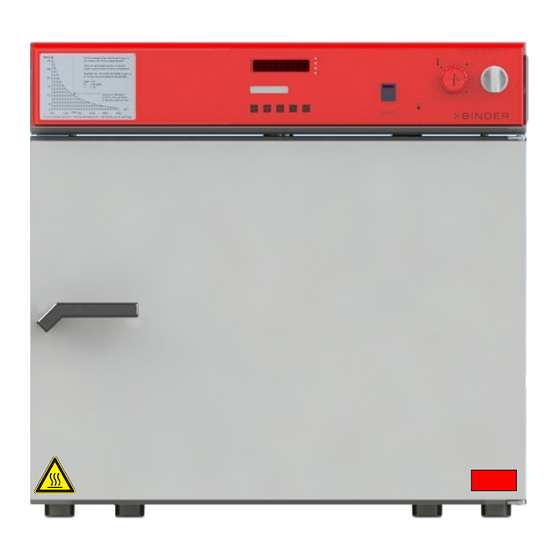
Pictograms (Warning signs) Service label Hot surface Figure 1: Position of labels on the chamber Keep safety labels complete and legible. Replace safety labels that are no longer legible. Contact BINDER Service for these replacements. FDL (E2.1) 05/2016 page 6/75... -
Page 7: Type Plate
FDL 115 Serial No. 00-00000 Im Mittleren Ösch 5 E2.1 Made in Germany 78532 Tuttlingen / Germany www.binder-world.com Figure 2: Type plate (example of FDL 115 regular chamber) Indications of the type plate Information BINDER Manufacturer: BINDER GmbH FDL 115 Model... -
Page 8: General Safety Instructions On Installing And Operating The Chambers
213-850 on safe working in laboratories (formerly BGI/GUV-I 850-0, BGR/GUV-R 120 or ZH 1/119, issued by the employers’ liability insurance association) (for Germany). BINDER GmbH is only responsible for the safety features of the chamber provided skilled electricians or qualified personnel authorized by BINDER perform all maintenance and repair, and if components relat- ing to chamber safety are replaced in the event of failure with original spare parts. -
Page 9: Intended Use
Intended use The BINDER safety drying oven FDL 115 is suitable for drying and burn in of lacquers and similar liquid coating materials which are containing solvents that can form explosive mixtures with air. The maximally permitted drying temperature and the maximally permitted quantity of solvent are limited, see chap. -
Page 10: Measures To Prevent Accidents
Measures to prevent accidents During drying of fluid paints, flammable solvent/air mixtures can form and ignite. The manufacturer took the following measures to prevent ignition and explosions: • Indications on the type plate See operating manual chap. 1.4 • Operating manual An operating manual is available for each safety drying oven. - Page 11 • Safety in case the technical ventilation fails The heating only turns on if the air circulation is already in operation. If the air circulation fails, the heating immediately turns off. In addition, there is a visual signal: red in- dicator light “AIR”...
-
Page 12: Important Points To Consider Before Commissioning
Important points to consider before commissioning 1.9.1 Technical ventilation / permissible load For safety reasons, the formation of a dangerous, explosive atmosphere must be avoided in all operating modes (see GUV-R 500 chap. 2.28 “Betreiben von Trocknern für Beschichtungsstoffe” ("Dryers for coat- ing materials")). -
Page 13: Chamber Description
Chamber description The safety drying oven FDL 115 was built according to EN 1539:2015 (“Dryers and ovens, in which flammable substances are released. Safety requirements”). The fan in the rear of the safety drying oven delivers a constant amount of fresh air through the working area irrespective of the drying temperature. -
Page 14: Chamber Overview
Chamber overview START Figure 3: Front view FDL 115 Control panel Microprocessor program controller RD3 Temperature safety device class 2 according to DIN 12880:2007 Main power switch ON/OFF Solvent curve Door handle Chamber door FDL (E2.1) 05/2016 page 14/75... -
Page 15: Control Panel
Control panel (4) (3) (2) (2a) (2b) (1) START Figure 4: Control panel of FDL 115 standard chamber Main power switch ON/OFF Temperature safety device class 2 (2a) Red pilot lamp for temperature safety device class 2 (2b) RESET key for temperature safety device Red indicator light “AIR”: Heating turned off during prepurge or due to insufficient exhaust air... -
Page 16: Completeness Of Delivery, Transportation, Storage, And Installation
Note on second-hand chambers (Ex-Demo-Units): Second-hand chambers are chambers that were used for a short time for tests or exhibitions. They are thoroughly tested before resale. BINDER ensures that the chamber is technically sound and will work flawlessly. Second-hand chambers are marked with a sticker on the chamber door. Please remove the sticker be- fore commissioning the chamber. -
Page 17: Guidelines For Safe Lifting And Transportation
• Permissible ambient temperature range during transport: -10 °C / 14 °F to +60 °C / 140 °F. You can order transport packing and pallets for moving or shipping purposes from BINDER service. Storage Intermediate storage of the chamber is possible in a closed and dry room. -
Page 18: Installation Of The Equipment
CAUTION Danger by stacking. Damage to the chambers. ∅ Do NOT place safety drying ovens on top of each other. To completely separate the chamber from the power supply, you must disconnect the power plug. Install the chamber in a way that the power plug is easily accessible and can be easily pulled in case of danger. Do not install or operate the oven in potentially explosive areas. -
Page 19: Electrical Connection
Electrical connection The safety drying oven FDL 115 is supplied ready for connection. • Power connection: fixed power connection cable 1800 mm / 5.9 ft in length with a shockproof plug. The socket must also provide a protective conductor. • Power supply voltage 230 V +/- 5 % at 50 Hz, 230 V +/- 5 % at 60 Hz. Current type 1N~ •... -
Page 20: Start Up
Start up After connecting the electrical supply (chap. 4.2), you can turn on the chamber. After loading the chamber, close the chamber door. • Turn on the chamber by setting the main power switch (1) to position “I”. Indicator light “AIR” (3) is lit, indicating that the heating has not yet been released by the air flow moni- toring. - Page 21 (setting in the user level, chap. 10). This setting is then valid for all program sections. Programming can be done directly via the controller keyboard or graphically at the computer using the software APT-COM™ 3 DataControlSystem (option, chap. 13.1) specially developed by BINDER. FDL (E2.1) 05/2016...
-
Page 22: General Indications
General indications The program controller RD3 offers several functional levels: Normal Display / fixed value operation: • Display of the actual value of temperature (display 1) and of the actual date and time (display 2). • The chamber is in fixed value operating mode, adjusting to the entered set-points. Fixed value entry mode (chap. -
Page 23: Fixed Value Entry Mode
Fixed value entry mode If you do not want to use the week program timer, deactivate it (factory setting, setting in the user level, chap. 10) before entering any set-points. Basic entry principle: Access the individual parameters with button X/W one after the other. Enter the values with the arrow keys. -
Page 24: Week Program Editor
Week program editor The Week program editor permits defining up to 4 shift point for each week day. A shift point defines a moment and the switching state ON or OFF of the channels that become active in this instance. Channel function: •... - Page 25 Display 1 shows 0000 Display 2 shows Shiftpt. (no function) Press program key Display 1 shows 0000 (selection of the shift point) Display 2 shows Shiftpt. (actual shift point: 1) Select the shift point (1 up to 4) with key Value is shown in display 2.
-
Page 26: Program Table Template For Week Program Editor
Program table template for Week program Editor Program editor Program title Project Date: Day of the week Time Channel 1 Channel 2* (temperature) hh:mm ON = SP2 OFF = SP1 Monday Tuesday Wednesday Thursday Friday Saturday Sunday * Channel 2 is non-functional in the standard chamber FDL (E2.1) 05/2016 page 26/75... -
Page 27: Program Editor
Program editor Selecting between set-point ramp and set-point step You can program various kinds of temperature transitions. In the user level (chap. 10) you can select between the settings “Ramp” (default setting) and “Step”. Setting “Ramp” permits programming all kinds of temperature transitions. With setting “Step”... - Page 28 Program entry as set-point ramp (example): W/°C t/min. Program table corresponding to the diagram (with default setting “Ramp”): Section Temperature Section length set-point [hh.mm] [ °C] TEMP TIME 00:30 01:30 01:00 03:20 00:01 The values of such a program table can now be entered to the RD3 program controller (chap. 8.2). Program entry as set-point step (example): S01 S02 W/°C...
-
Page 29: Programming With Setting "Step
Program table corresponding to the diagram (with default setting “Ramp”): Section Temperature Section length set-point [hh.mm] [ °C] TEMP TIME 00:30 00:01 01:30 00:01 01:00 00:01 03:20 00:01 The values of such a program table can now be entered to the RD3 program controller (chap. 8.2). The end point of the desired cycle must be programmed with an additional section (in our examples S05 for set-point ramp and S08 for set-point step) with a section time of at least one minute. -
Page 30: General Notes On Programming Temperature Transitions
Program table corresponding to the diagram (with setting “Step”): Section Temperature Section length set-point [hh.mm] [ °C] TEMP TIME 00:30 01:30 01:00 03:20 The values of such a program table can now be entered to the RD3 program controller (chap. 8.2). 8.1.3 General notes on programming temperature transitions If the tolerance limits set in the user level (chap. - Page 31 – Step 1 Selecting the program and the program section: Normal Display Display 1 shows e.g. 39.8 (actual temperature value) (actual date and time, actual state of week program timer Display 2 shows e.g. 15.01.07 13:52 - - channel 1: Off, channel 2: Off) Press down key for 5 sec.
- Page 32 Next step – set-point entry in the desired program sections: Basic entry principle: Access the parameters of individual program sections with button X/W one after the other. Enter the values of the individual parameters with the arrow keys. A value flashing once after 2 seconds indicates that it has been adopted by the controller.
-
Page 33: Program Table Template
Program table template Program editor Program title Project Program No. Date: Section Temperature set-point Section length [ °C] [hh.mm] TEMP TIME FDL (E2.1) 05/2016 page 33/75... -
Page 34: Deleting A Program Section
Deleting a program section A program section is deleted from the program by setting the section duration to Zero. Normal display Press down key for 5 sec. Display 1 shows e.g. 0000 Display 2 shows PROGRAM EDITOR (you are in the program editor) Press program key Display 1 shows 0000... -
Page 35: Program Start Level
The following section (in our example now S03) is displayed: Display 1 shows e.g. 03 (actual selection of the section: S03) Display 2 shows P01:S03 (program section can be selected) alternating CONTINUE X/W (information: set-point entry with X/W) Press key EXIT or wait 120 sec Controller returns to Normal Display If you delete a program section which is followed by further sections, those following move up... - Page 36 Then define the settings for the program course. Two parameters can be set: • Program delay time, i.e. a defined time before a program starts. It can be entered with a precision of 1 minute, and its maximum value is 99.59 (99 hs 59 min). If the value is 00.00, the program will start immediately.
-
Page 37: User Level
During program course the arrow keys and the EXIT button are not functional. By pressing the program key for 3 seconds, you can terminate the program course. If you press button during program course, the entered set-point of the actually running program sec- tion is shown for 5 seconds: Display 1 shows e.g. - Page 38 • Selection of controller menu language (Language) Select German, English, or French. • Counter of operating hours (Oper.hs) Information about the number of operating hours currently reached or since the last reset. (no setting, display only). • Max. number of operating hours (Op.limit) Enter a limit number of operating hours, i.e., the maximum number of operating hours that can be run.
- Page 39 • Tolerance limit range (Tol.band) Entry of a tolerance limit value in °C. If the actual value of temperature exceeds the set-point of a pro- gram section by more than the entered tolerance limit value, the program is halted (LED (3d) flashing) until the actual temperature value is again within the tolerance range.
- Page 40 Normal Display Display 1 shows e.g. 19.8 (actual temperature value) (actual date and time, actual switching state of week pro- Display 2 shows e.g. 15.05.06 13:52 - - gram timer channel 1: Off, channel 2: Off) Press down key for 5 sec Display 1 shows e.g.
- Page 41 Press key Display 1 shows 0000 (no function) (setting of the alarm buzzer) Display 2 shows Buzzer Active (actual setting: „Active“) Select between “Active” and “Inactiv” using Setting is shown in display 2. arrow keys Press key Display 1 shows 0000 (no function) (selection of controller language)
- Page 42 Press key Display 1 shows 0000 (1 program with max. 20 sections or Display 2 shows PrgSelec: 2Prg10S 2 programs with max. 10 sections each?) (actual setting: 2Prg10S) Select between “2Prg10S” and “1Prg20S” Setting is shown in display 2. using arrow keys Press key Display 1 shows 0000...
- Page 43 Press key Display 1 shows 0000 Display 2 shows Date (Main menu: Setting the date of the real time clock) Press program key Display 1 shows e.g. 2006 (Actual setting: 2006) Display 2 shows Year 2006 (Setting the year of the real time clock) Set year (2006 up to 2050) using arrow keys Setting is shown in display 2.
-
Page 44: Behavior In Case Of Failures
Behavior in case of failures 11.1 Behavior after a power failure Power failure during fixed-value operation (Normal Display): the entered parameters remain saved. After the power returns, indicator light “AIR” (3) is lit, indicating that the heating has not yet been released by the air flow monitoring. - Page 45 (2b) (2a) Figure 8: Safety thermostat class 2 Function: The safety thermostat class 2 is functionally and electrically independent of the temperature control de- vice and turns off the chamber at all poles. When the control knob (2) is set to the end stop (position 10), the safety thermostat class 2 acts as a chamber protection device.
-
Page 46: Exhaust Air Monitoring
The chamber is only active when the reset button (2b) is pushed in. When the safety thermostat class 2 responds, the red alarm lamp (2a) illuminates, the reset button (2b) pops out and the chamber turns off permanently at all poles. Only the fan keeps turning for safety rea- sons. -
Page 47: Options
Options 13.1 Communication software APT-COM™ 3 DataControlSystem (option) The chamber is regularly equipped with a serial interface RS 422 that can connect the BINDER commu- nication software APT-COM™ 3 DataControlSystem. The connection to a computer is established using the FDL interface via an interface converter RS 422 / RS 232. -
Page 48: Additional Measuring Channel For Digital Object Temperature Indicator With Pincer-Type Sensor (Option)
The object temperature data are put out together with the data of the temperature controller to the RS 422 interface as a second measuring channel and can be documented by the communication software APT-COM™ developed by BINDER (option, chap. 13.1). Socket... -
Page 49: Maintenance, Cleaning, And Service
Record the results of the maintenance tests in a service log Replace the door gasket only when cold. Otherwise, the door gasket may become damaged. We recommend taking out a maintenance agreement. Please consult BINDER Service. BINDER telephone hotline: +49 (0) 7462 2005 555... -
Page 50: Cleaning And Replacing The Intake Filter
14.2 Cleaning and replacing the intake filter The fresh air intake filter (fine particle filter for particles 1 µm up to 10 µm, class M6 acc. to EN 779:2012) at the top right-hand side must be cleaned or replaced from time to time, depending on the degree of soiling. - Page 51 We recommend using the neutral cleaning agent Art. No.1002-0016 for a thorough cleaning. Any corrosive damage that may arise following use of other cleaning agents is excluded from liability by BINDER GmbH. Any corrosive damage caused by a lack of cleaning, is excluded from liability by BINDER GmbH. CAUTION Danger of corrosion.
-
Page 52: Decontamination
For chemical disinfection, we recommend using the disinfectant spray Art. No. 1002-0022. Any corrosive damage that may arise following use of other disinfectants is excluded from liability by BINDER GmbH. With every decontamination method, always use adequate personal safety controls. -
Page 53: Sending The Chamber Back To Binder Gmbh
14.6 Sending the chamber back to BINDER GmbH If you return a BINDER product to us for repair or any other reason, we will only accept the product upon presentation of an authorization number (RMA number) that has previously been issued to you. An authorization number will be issued after receiving your complaint either in writing or by telephone prior to your sending the BINDER product back to us. -
Page 54: Decommissioning
(Elektro- und Elektronikgerätegesetz, ElektroG from 20 Octo- ber 2015, BGBl. I p. 1739) or contact BINDER service who will organize taking back and disposal of the chamber according to the German national law for electrical and electronic equipment (Elektro- und El- ektronikgerätegesetz, ElektroG from 20 October 2015, BGBl. -
Page 55: Disposal Of The Chamber In The Member States Of The Ec Except For The Federal Republic Of Germany
According to Annex I of Directive 2012/19/EU of the European Parliament and of the Council on waste electrical and electronic equipment (WEEE), BINDER devices are classified as “monitoring and control instruments” (category 9) only intended for professional use“. They must not be disposed of at public collecting points. -
Page 56: Disposal Of The Chamber In Non-Member States Of The Ec
15.5 Disposal of the chamber in non-member states of the EC CAUTION Alteration of the environment. For final decommissioning and disposal of the chamber, please contact BINDER ser- vice. Follow the statutory regulations for appropriate, environmentally friendly disposal. -
Page 57: Troubleshooting
Controller not adjusted. Calibrate and adjust controller. LED “AIR” (3) is not lit. Controller defective. Pt 100 sensor defective. Contact BINDER service. Chamber heating permanently, set-point not maintained. Semiconductor relay defective Controller not adjusted. Calibrate and adjust controller. - Page 58 (chap. 10). (chap. 10). Only qualified service personnel authorized by BINDER must perform repair. Repaired chambers must comply with the BINDER quality standards. Every fire and explosion in relation to a lacquer dryer must be reported to the employer’s liabil- ity insurance association (for Germany).
-
Page 59: Technical Description
(certified since December 1996 by TÜV CERT). All test equipment used is subject to the administration of measurement and test equipment that is also constituent part of the BINDER QM DIN EN ISO 9001 sys- tems. They are controlled and calibrated to a DKD-Standard at regular intervals. - Page 60 Interior dimensions Width mm / inch 600 / 23.62 Height mm / inch 435 / 17.13 Depth mm / inch 435 / 17.13 Interior volume l / cu.ft 115 / 4.1 Total steam space volume l / cu.ft. 156 / 5.51 Racks Quantity of racks (regular) Quantity of racks (max.)
- Page 61 +22 °C ± 3 °C / 71.6 °F ± 5.4 °F and a power supply voltage fluctuation of +/- 5%. Technical data is determined in accordance to BINDER Factory Standard Part 1:2015 following DIN 12880:2007. All indications are average values, typical for chambers produced in series. We reserve the right to change technical specifications at any time.
-
Page 62: Equipment And Options (Extract)
17.4 Equipment and Options (extract) To operate the safety drying oven, use only original BINDER accessories or accessories / components from third-party suppliers authorized by BINDER. The user is responsible for any risk arising from using unauthorized accessories. Regular equipment Electronically controlled APT.line™... -
Page 63: Accessories And Spare Parts (Extract)
17.5 Accessories and spare parts (extract) BINDER GmbH is responsible for the safety features of the chamber only, provided skilled electricians or qualified personnel authorized by BINDER perform all maintenance and repair, and if components relating to chamber safety are replaced in the event of failure with original spare parts. -
Page 64: Dimensions Fdl 115
17.6 Dimensions FDL 115 Figure 16: Dimensions FDL 115 FDL (E2.1) 05/2016 page 64/75... -
Page 65: Certificates And Declarations Of Conformity
Certificates and declarations of conformity 18.1 EU Declaration of Conformity FDL (E2.1) 05/2016 page 65/75... - Page 66 FDL (E2.1) 05/2016 page 66/75...
-
Page 67: Certificate For The Gs Mark Of Conformity Of The "Deutsche Gesetzliche Unfallversicherung E.v." (German Social Accident Insurance (Dguv)
18.2 Certificate for the GS mark of conformity of the “Deutsche Gesetzliche Un- fallversicherung e.V.” (German Social Accident Insurance (DGUV) FDL (E2.1) 05/2016 page 67/75... - Page 68 FDL (E2.1) 05/2016 page 68/75...
-
Page 69: Product Registration
Product registration FDL (E2.1) 05/2016 page 69/75... -
Page 70: Contamination Clearance Certificate
Contamination clearance certificate Unbedenklichkeitsbescheinigung 20.1 For chambers located outside USA and Canada Declaration regarding safety and health Erklärung zur Sicherheit and gesundheitlichen Unbedenklichkeit The German Ordinance on Hazardous Substances (GefStofV), and the regulations regarding safety at the workplace, require that this form be filled out for all products that are returned to us, so that the safety and the health of our employees can be guaranteed. - Page 71 Kind of transport / transporter / Transportweg/Spediteur: Transport by (means and name of transport company, etc.) Versendung durch (Name Spediteur o.ä.) ___________________________________________________________________________________ Date of dispatch to BINDER GmbH / Tag der Absendung an BINDER GmbH ___________________________________________________________________________________ FDL (E2.1) 05/2016 page 71/75...
- Page 72 We are aware that, in accordance with Article 823 of the German Civil Code (BGB), we are directly liable with regard to third parties, in this instance especially the employees of BINDER GmbH, who have been entrusted with the handling / repair of the unit / component. / Es ist uns bekannt, dass wir gegenüber Dritten –...
-
Page 73: For Chambers In Usa And Canada
After we have received and reviewed the complete information we will decide on the issue of a RMA number. Please be aware that size specifications, voltage specifications as well as performance specifi- cations are available on the internet at www.binder-world.us at any time. Take notice of shipping laws and regulations. - Page 74 Customer (End User) Decontamination Declaration Health and Hazard Safety declaration To protect the health of our employees and the safety at the workplace, we require that this form is com- pleted by the user for all products and parts that are returned to us. (Distributors or Service Organizations cannot sign this form) NO RMA number will be issued without a completed form.
- Page 75 4.5 Shipping laws and regulations have not been violated. I hereby commit and guarantee that we will indemnify BINDER Inc. for all damages that are a consequence of incomplete or incorrect information provided by us, and that we will indemnify and hold harmless BINDER Inc.
Need help?
Do you have a question about the FDL 115 and is the answer not in the manual?
Questions and answers