
Subscribe to Our Youtube Channel
Related Manuals for Beckhoff XTS Hygienic


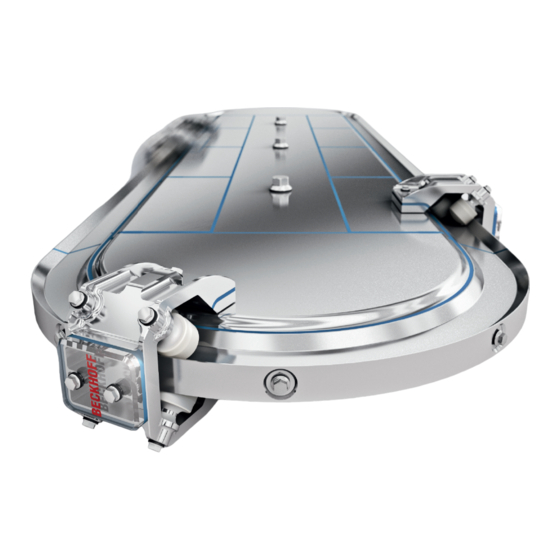
Summary of Contents for Beckhoff XTS Hygienic
- Page 1 Transport System | XTS Hygienic Operating Instructions | EN 5/7/2020 | Version 1.0...
-
Page 3: Table Of Contents
Ordering options ............................. 25 Intended use .............................. 27 Technical data.............................. 28 Definition ................................. 28 Data for operation and environment ....................... 29 XTS Hygienic .............................. 30 Dimensional drawings............................. 32 Scope of supply .............................. 44 Packaging ............................... 44 Transport and storage............................ 45 Conditions ............................... - Page 4 Table of contents Accessories................................ 86 Rail on support.............................. 86 6-roller 75 mm mover............................ 86 Fault correction.............................. 87 Motor modules .............................. 87 TcIoXts object .............................. 90 SoftDrive object............................... 94 Decommissioning.............................. 96 Disassembly.............................. 96 Disposal ................................ 97 Index ................................... 98 ─── eXtended Transport System Version: 1.0...
-
Page 5: Documentation Notes
• EP1590927 • EP1789857 • EP1456722 • EP2137893 • DE102015105702 ® EtherCAT is a registered trademark and patented technology, li- censed by Beckhoff Automation GmbH & Co. KG, Germany. Version: 1.0 eXtended Transport System ───... - Page 6 • Use of untrained personnel • Use of unauthorized spare parts Copyright © Beckhoff Automation GmbH & Co. KG, Germany 1.1.4 The copying, distribution and utilization of this document as well as the communication of its contents to others without express autho- rization is prohibited.
-
Page 7: Version Numbers
Product features Only the product properties specified in the current operating in- structions are valid. Further information given on the product pages of the Beckhoff homepage, in emails or in other publications is not authoritative. Scope of the documen- Apart from these operating instructions, the following documents are... -
Page 8: Staff Qualification
Documentation notes Staff qualification These operating instructions are intended for trained control and au- tomation specialists with knowledge of the applicable and required standards and directives. Qualified personnel must have knowledge of drive technology and electrical equipment as well as knowledge of safe working on electri- cal systems and machines. - Page 9 • Independently optimize and carry out their work Customer service Customer service personnel and service personnel are verifiably trained and authorized by Beckhoff or the machine manufacturer for the work on the machine or plant. Version: 1.0 eXtended Transport System...
-
Page 10: Safety And Instruction
Documentation notes Safety and instruction Read the contents that refer to the activities you have to perform with the product. Always read the chapter For your safety in the op- erating instructions. Observe the warning notes in the chapters so that you can handle and work properly and safely with the product. - Page 11 Documentation notes Notes Notes are used for important information on the product. The possible consequences of failure to observe these include: • Malfunctions of the product • Damage to the product • Damage to the environment Informations This sign indicates information, tips and notes for dealing with the product or the software.
-
Page 12: Beckhoff Services
Beckhoff and the worldwide partner companies offer comprehensive support and service. Support The Beckhoff Support offers technical advice on the use of individ- ual Beckhoff products and system planning. Staff provide assistance 1.7.1 for programming and commissioning complex automation systems and offer a comprehensive training program. -
Page 13: For Your Safety
For your safety Read this chapter containing general safety information. The chap- ters in these operating instructions also contain warning notices. Al- ways observe the safety instructions for your own safety, the safety of other persons and the safety of the product. When working with control and automation products, many dangers can result from careless or incorrect use. - Page 14 For your safety Do not use damaged components Observe the specifications in the technical data during storage, transport and operation. Do not use damaged components. Risk of injury when handling cutting tools You can sustain cutting or puncturing injuries through careless work- ing with cutting tools.
- Page 15 For your safety Avoid overheating Operate the components according to the technical specifications. Refer here to the chapter: "Technical data". Provide for adequate cooling and switch the components off immediately if the tempera- ture is too high. Do not touch moving or rotating components Do not touch moving or rotating parts during operation.
-
Page 16: Product Overview
Product overview Number Explanation Curved rail Lock Mover LED status display Cover with connection card Straight guide rail with lock Cover with supply Machine bed Straight guide rail without lock Straight module Curved module ─── eXtended Transport System Version: 1.0... -
Page 17: Led Status Display
Product overview LED status display Number Explanation 48 V | 16 A power supply status LED 24 V | 4 A power supply status LED Link / Act status LED EtherCAT status LED Drive State status LED Version: 1.0 eXtended Transport System ───... -
Page 18: Name Plate
Product overview Name plate The name plate is located on the system side opposite the LED sta- tus display. Number Explanation Product designation Series Serial number EAC conformity RoHS conformity CE conformity cURus approval Firmware and hardware revision XML sensor PCB revision number XML motor PCB revision number Date of manufacture - week/year ───... -
Page 19: Type Key
Product overview Type key Module ATH 20xx – xxxx – 000x Explanation Product line AT = drive technology Series H = Hygienic Design Product type 20 = module Module variants 00 = straight 01 = straight with supply 50 = 180° curve, clothoid 51 = 180°... - Page 20 Product overview Guide rail ATH 9xxx – xxxx – 0075 Explanation Product line AT = drive technology Series H = Hygienic Design Product type 0 = without lock 1 = with lock 2 = connector for straight rails Rail variants 00 = straight 50 = 180°...
-
Page 21: Product Characteristics
24 V control voltage and a 48 V load voltage. Software-based control The XTS Hygienic is controlled by a software-based cascade con- troller. The control loop structure is stored in the XTS drivers and is calculated cyclically on the control IPC. You do not need any addi- tional drive software. -
Page 22: Components
Product overview Components A complete XTS Hygienic system consists of: • Motor modules • Guide rails • Movers The individual components are defined via the type key and can be ordered separately or preconfigured as a complete system. Motor modules A system consists of individual motor modules that can be combined to form a complete drivetrain. - Page 23 Product overview Guide rails In addition to the motor modules you need a rail system, which con- sists of various guide rails. The guide rails are available in different 3.5.2 versions. Straight guide rails 3.5.2.1 3.5.2.1 Without lock Straight guide rails are available in the following lengths without lock cover: Available lengths 250 mm...
- Page 24 Product overview Curved rail 180° clothoid The clothoid is available to suit the 180° curved module. Mover The movers are available in the following versions: 3.5.3 • stainless steel • or aluminum Stainless steel The stainless steel mover is 75 mm long, has 6 rollers and is mounted with a magnetic plate set.
-
Page 25: Ordering Options
Product overview Ordering options Ordering options are defined via the type key and must be ordered separately. The listed components cannot be retrofitted. Mover 1 3.6.1 3.6.1 Stainless steel The stainless steel mover with the Mover 1 magnetic plate set is available as a 75 mm mover with 6 guide rollers. - Page 26 3.6.2 The magnetic plate set is available for Beckhoff 75 mm movers are well as for third-party movers. The Mover 1 magnetic plate set is available for Beckhoff 75 mm movers are well as for third-party movers. ─── eXtended Transport System...
-
Page 27: Intended Use
Any use exceeding the permissible values specified in the Technical data is considered improper and therefore prohibited. 3.7.1 The XTS Hygienic is not suitable for use in the following areas: • in ATEX zones without a suitable housing The relevant standards and directives for EMC interference emis- sions must be complied with in residential areas. -
Page 28: Technical Data
Technical data Below you will find definitions of terms, environmental conditions and operating specifications as well as technical data. Definition All details relate to an ambient temperature of 40 °C. The data can have a tolerance of +/- 10%. Technical terms Nominal force F 4.1.1 Nominal force that a mover can continuously apply. -
Page 29: Data For Operation And Environment
Operate the XTS Hygienic only under the specified environ- mental conditions Operate the Beckhoff XTS Hygienic only in accordance with the specifications for operation and the environment listed in this chap- ter. This ensures a long service life and proper operation. -
Page 30: Xts Hygienic
Technical data XTS Hygienic Electrical data Control voltage [V Power supply [V Current consumption - power supply nominal current [A] Power consumption control voltage module [W/m] Maximum segment length per power ≤ 3 supply module [m] At a constant velocity [m/s]... - Page 31 Technical data System properties Maximum force at standstill [N] Dependent on the air gap between stator and drive magnet Force constant K at standstill [N/A] Maximum force at 2 m/s [N] Velocity at 48 V [m/s] Acceleration without payload [m/s ≥ 75 Nominal force F Winding resistance of a phase R [Ω]...
-
Page 32: Dimensional Drawings
Technical data Dimensional drawings Dimensional drawings and 3D models online You have the option to download the dimensional drawings and 3D models of the individual components from the Beckhoff website: www.beckhoff.de/download Modules 4.4.1 ATH2000-0250 Straight module All figures in millimeters ───... - Page 33 Technical data ATH2001-0250 Straight module with supply All figures in millimeters Version: 1.0 eXtended Transport System ───...
- Page 34 Technical data ATH2050-0500 Clothoid module 180° curve All figures in millimeters ─── eXtended Transport System Version: 1.0...
- Page 35 Technical data ATH2051-0500 Clothoid module 180° curved with supply All figures in millimeters Version: 1.0 eXtended Transport System ───...
- Page 36 Technical data Mover 4.4.2 ATH9011-0075-0550 Stainless steel mover • Length 75 mm • 6 guide rollers All figures in millimeters ─── eXtended Transport System Version: 1.0...
- Page 37 Technical data ATH9011-0075-1550 Stainless steel mover 1 • Length 75 mm • 6 guide rollers All figures in millimeters Version: 1.0 eXtended Transport System ───...
- Page 38 Technical data ATH9013-0075-0550 Aluminum mover • Length 75 mm • 6 guide rollers All figures in millimeters ─── eXtended Transport System Version: 1.0...
- Page 39 Technical data ATH9013-0075-1550 Aluminum mover 1 • Length 75 mm • 6 guide rollers All figures in millimeters Version: 1.0 eXtended Transport System ───...
- Page 40 Technical data Magnetic plate set 4.4.3 ATH9001-0550-0001 Standard magnetic plate set All figures in millimeters ─── eXtended Transport System Version: 1.0...
- Page 41 Technical data ATH9001-0550 Magnetic plate set for third-party movers All figures in millimeters 55,4 - min. min. (35,4) (5,5) (5,5) (82,4) Version: 1.0 eXtended Transport System ───...
- Page 42 Technical data ATH9001-1550-0001 Mover 1 magnetic plate set All figures in millimeters ─── eXtended Transport System Version: 1.0...
- Page 43 Technical data ATH9001-1550 Mover 1 magnetic plate set for third-party movers All figures in millimeters 55,4 - min. min. (35,4) (5,5) (5,5) (82,4) Version: 1.0 eXtended Transport System ───...
-
Page 44: Scope Of Supply
Scope of supply Check missing or damaged parts Check your delivery for completeness. If any parts are missing or became damaged during transport, contact the carrier, vendor or our service department immediately. Packaging Instructions for handling are printed on the packaging: Carton Symbol Explanation... -
Page 45: Transport And Storage
• Use of the vendor's original packaging Long-term storage Perform recurring inspections Check every six months that the XTS Hygienic is in good condition. Damage to the XTS Hygienic or failure to carry out maintenance work can shorten the service lives of the installed components and parts. -
Page 46: Mechanical Installation
Mechanical installation WARNING Wear safety shoes Wear safety shoes when assembling the XTS Hygienic, as com- ponents may inadvertently fall down in the working area. Falling components can lead to serious injuries to the feet. Handle cutting tools carefully Use cutting tools with great care. Make sure that nobody in your immediate vicinity can be injured if the tool inadvertently slips. - Page 47 Mechanical installation Avoid dirt When assembling the XTS Hygienic, make sure that all parts are free from dust and dirt. Check that the machine bed has been manufactured correctly Check before assembling whether the distances between the locat- ing pins in the machine bed are correct.
-
Page 48: Preparation
Mechanical installation Preparation The illustration below gives you an initial overview of the compo- nents that you need for the mechanical installation of the XTS Hy- gienic in the configuration described here. Please note that the de- sign and composition of the components can deviate and that not all fastening materials are included in the scope of supply as standard. - Page 49 Mechanical installation Number Name Straight modules Straight guide rails with lock Straight guide rails without lock Curved modules Curved rails Rail on support Guard plate for rail on support Stainless steel mover 75 mm, depending on application Aluminum steel mover 75 mm, depending on application Cover with connection card Cover with supply Seals for covers...
-
Page 50: Modules
Mechanical installation Technical aids For the mechanical installation you need the following aids: 7.1.1 • Suitable torque wrench • Suitable screwdrivers • Cutting tool such as scalpel or hobby knife • Adhesive: Elastosil E43 N • Vaseline with brush • Lint-free cloth Modules ►... - Page 51 Mechanical installation ► Place module 1 on the machine bed 2 ► Screw in the screws with sealing ring 3 in the center of the mod- ule, leaving only a minimal gap ► Place further modules 1, the second curved module 2 and fur- ther modules on the opposite side 3 in a row, thereby screwing in screws with sealing rings, leaving only a minimal gap in each case...
-
Page 52: Seals
Mechanical installation Seals ► Grease the gap 2 between modules 1 and 3 with Vaseline ► Push seal 1 between the modules, folding the seal end 2 to the side ► Carefully brush the upper part of the seal downwards with a little pressure ►... - Page 53 Mechanical installation Make sure the seals are seated correctly Make sure that the O-ring contours are seated correctly in the in- tended grooves. If seals are mounted improperly, fluid can penetrate into the elec- trical interfaces and damage the system. ►...
- Page 54 Mechanical installation ► Press the short end of the seal 1 into the corners 2 on the curved module with your fingernail, then mount the straight part of the seal in the same way ► To facilitate mounting, lift or move the modules slightly ►...
- Page 55 Mechanical installation ► Mount the long end of seal 2 on the other side of the curved module 1 in the same way ► Screw in the screws of the curved module hand tight in order to fix the seals on both sides Allow the seal legs to overlap When assembling, the long legs of the seals must overlap the short end.
- Page 56 Mechanical installation ► Screw in the screws with sealing rings 2 on the straight module 1 hand tight ► Mount the other screws with sealing rings on the straight mod- ules in the same way, except on the two straight modules with overlapping seals ►...
- Page 57 Mechanical installation ► Screw in screws 1 in order to fix the locating pin 2 between the modules ► Fix all other locating pins between the modules in the same way with screws Version: 1.0 eXtended Transport System ───...
-
Page 58: Interfaces
Mechanical installation Interfaces Grease the edge 2 on the cover with power supply 1 with Vaseline ► Place the cover 1 on the interface 2, ensuring the correct align- ment of the connector ► Screw in the screws with sealing rings 3 and 4 tightly ►... - Page 59 ► Check whether the appropriate covers with connection card have been inserted ► Contact the Support/Applications Department TwinCAT Beckhoff also recommends checking the modules using the Twin- CAT software. ► Connect EtherCAT connector to the control computer ► Start a TwinCAT project ►...
-
Page 60: Guide Rails
Mechanical installation Guide rails Lock for mounting movers A 250 mm-long guide rail serves as a lock for mounting the movers on the guide rails. For the assembly, the lock should be replaced by a rail on support. Further information is given in the course of the mechanical instal- lation in the chapter Mover. - Page 61 Mechanical installation Align the rails to fit the modules The guide rails must be mounted on the modules in a certain alignment. To do this, position the bore holes in the rails over the tapped holes in the modules. If the alignment is wrong, the screws will not mate with the tapped holes in the modules and cannot be screwed in.
- Page 62 Mechanical installation ► Press seal 1 into the groove between module 2 and straight guide rail 3 with your fingernail ► To facilitate mounting, lift or move the guide rail slightly ► Continue pressing the seal in up to the end of the guide rail ►...
- Page 63 Mechanical installation Curved rails 7.5.2 7.5.2 ► Grease the support surfaces 1 and 2 of the curved rail 3 with Vaseline ► Insert locating pins 1 and 2 into the curved rail 3 ► Insert locating pins 1 and 4 into the guide rails ► Push seals 2 and 3 with the pre-cut edge downwards onto the lo- cating pins ►...
- Page 64 Mechanical installation ► Guide seal 2 around the curved module 3 from top to bottom ► Press seal into the groove between curved module and curved rail 1 and 4 with your fingernail ► Guide the seal on the other side of the system around the curved module in the same way ►...
- Page 65 Mechanical installation ► Push curved rail 1 carefully onto curved module 2 ► Make sure that the seal remains in place ► Screw the screw with sealing ring 2 in the center of the curved rail hand tight in order to press the curved rail completely against the curved module ►...
- Page 66 Mechanical installation ► Apply adhesive to one end 1 ► Press the end into the groove in order to glue the two ends to- gether ► Remove surplus adhesive with a lint-free cloth ► Glue the seal on the other side of the system in the same way ►...
- Page 67 Mechanical installation Completion of the assembly ► Screw all screws in the machine bed tight ► Observe tightening torques: Components Tightening torque [Nm] Screws, M5 x 20 ► Screw all screws on the guide rails of the entire system tight ►...
-
Page 68: Mover
Mechanical installation Mover Better running characteristics Beckhoff recommends greasing the running surfaces on the curved rails with Vaseline before mounting the movers and commissioning the XTS Hygienic. ► Grease the running surfaces on both sides of the curved rails 1 and 2 with Vaseline ►... - Page 69 If you do not hold the movers tight with both hands in a controlled manner, the magnetic forces can attract the movers in an uncon- trolled manner to the XTS Hygienic and cause serious crushing injuries to the hands and fingers or damage to the system.
- Page 70 Mechanical installation ► Make sure when mounting the movers that the guide rollers 1 of the movers do not press against the edges 2 of the rail on sup- port ► Place mover 1 carefully with both hands centrally onto the rail on support 2 As soon as you place the magnetic plate set 2 of the mover 1 in the vicinity of the module 3, the magnetic plate set and the module at-...
- Page 71 Mechanical installation When all remaining movers have been mounted: ► Check all round that the air gap between the magnetic plates 1 of the movers and the modules 2 is symmetrical on both sides of the system and is approximately 0.70 mm ► Check that the magnetic plates are positioned parallel to the modules Remove rail on support ►...
-
Page 72: Electrical Installation
Electrical installation Connection technology All modules of the XTS Hygienic have variable interfaces. Mounted on these interfaces are either covers with a connection card for elec- trically connecting modules together or covers with a supply. The covers with supply are delivered with an integrated and pre-as- sembled hybrid cable that combines the power cable with the Ether- CAT cable. -
Page 73: Pin Assignment Of The Power Cable
1 R1 R3 1 R1 R3 12 32 2 R2 R4 2 R2 R4 EtherCAT cable The following table shows the cable configuration for the power ca- ble of the XTS Hygienic: Wire color Signal Wire cross-section brown +48 V 4 mm blue GND, 48 V... -
Page 74: Earthing Of The Supply
U 48 V I 48V 4 mm² 4 mm² Load current circuit Beckhoff recommends that you don't earth the 48 V power supply unit The 24 V return line (1.5 mm ) could be overloaded. If the 48 V power supply unit is earthed, the currents will be distrib- uted to the 48 V... -
Page 75: Earthing Of The Machine Beds
Beckhoff recommends the use of wide connections with large contact surfaces. Wide earth straps are suitable for this. The table below illustrates typical suit-... - Page 76 Electrical installation Painted surfaces 8.4.1 8.4.1 ► Earth painted surface as shown in the figure with spring washer 1, washer 2, contact washer 3, nut 4 and bolt 5 Unpainted surfaces 8.4.2 8.4.2 ► Earth unpainted surface as shown in the figure with spring washer 1, washer 2, nut 3 and bolt 4 ───...
-
Page 77: Parallel Connection Of The Modules
See documentation on Puls website See documentation on Puls website Secondary fusing Overcurrent protection terminal Outlet to module with supply 24 V DC, 2-channel, 4 A/4 A, Beckhoff 16 A "B" circuit breaker, Siemens EL9222-6644 or EL9227-6644 with ex- 5SY6116-6 tended functions Outlet to brake chopper terminal 4 A "C"... - Page 78 See documentation on Puls website See documentation on Puls website Secondary fusing Overcurrent protection terminal Outlet to module with supply 24 V DC, 2-channel, 4 A/4 A, Beckhoff 16 A "B" circuit breaker, Siemens EL9222-6644 or EL9227-6644 with ex- 5SY6116-6 tended functions Outlet to brake chopper terminal 4 A "C"...
-
Page 79: Parallel Connection Of The Power Supply
Electrical installation parallel connection of Single-channel contactor switch-off The figure below shows a wiring example of a single-channel con- the power supply tactor switch-off: 11 31 1 R1 R3 1 R1 R3 1 R1 R3 1 R1 R3 1 R1 R3 1 R1 R3 1 R1 R3 1 R1 R3... - Page 80 See documentation on Puls website See documentation on Puls website Secondary fusing Overcurrent protection terminal Outlet to module with supply 24 V DC, 2-channel, 4 A/4 A, Beckhoff 16 A "B" circuit breaker, Siemens EL9222-6644 or EL9227-6644 with ex- 5SY6116-6 tended functions...
-
Page 81: Commissioning
• Observe information for environment and operation • Check protective measures against moving and live parts Configuration Beckhoff recommends the use of the latest TwinCAT XAE and TF5850 for the configuration of new projects • Create a new TwinCAT project and select the target system •... -
Page 82: Prerequisites During Operation
Commissioning Prerequisites during op- • Pay attention to atypical noise development eration • Pay attention to smoke development • Always check drive surfaces, cables and seals for dirt, leaks, moisture or dust • Check temperature development • Observe recommended maintenance intervals •... -
Page 83: Maintenance And Cleaning
• Minimum distance 30 cm • Maximum water temperature 80 °C • Maximum water pressure 80-100 bar • No rotary jet In addition, it is possible to clean the XTS Hygienic movers in a dish- washer. Version: 1.0 eXtended Transport System... -
Page 84: Intervals
Maintenance and cleaning Intervals Adapt the maintenance cycles in case of higher loads 10.2 Operation at the limits of the permissible environmental conditions and operating states will shorten the intervals. Depending on the mechanical dynamics due to mounted devices and movements, the service life of the mover rollers may be shortened. - Page 85 Maintenance and cleaning Component Interval Maintenance Lock Every month Clean the running surfaces Recommended cleaner: Isopropanol 6 months Check the mover lock for wear and break outs Check the fastening of the lock 6 months Check that the lock is seated correctly and whenever it is opened As required...
-
Page 86: Accessories
Accessories Rail on support 11.1 11.1 The XTS Hygienic movers are mounted on the guide rail by means of the rail on support. 6-roller 75 mm mover 11.2 11.2 The roller set is available for the replacement of worn or damaged guide rollers in the 75 mm-long stainless steel or aluminum movers... -
Page 87: Fault Correction
Fault correction The following tables describe a selection of errors that are displayed either as "warning" or "error" messages. Depending on the applica- tion, other causes may be responsible for the malfunction. Motor modules Changes from firmware version 15 12.1 Up to firmware version 14 From firmware version 15 0x4101... - Page 88 Fault correction Error 12.1.2 12.1.2 Message Error Number of the cause 0x8103 Undervoltage control voltage 24 V control voltage lower than 18.8 V 0x8104 Module overtemperature Motor module temperature exceeds 75 °C, see: COE 9000:19…9000:1C 0x8105 PD-Watchdog Process Data Watchdog: XTS Task has not sent any new data over three cycles 0x8109 Overvoltage control voltage...
- Page 89 Discharge brushes on the movers defective or missing Replace the discharge brushes Short-circuit in coil "x" of the motor module Contact Beckhoff Support Excessively heavy braking on coil "x" of the motor module Adjust the braking ramp Reduce the load weight on the movers...
-
Page 90: Tcioxts Object
Fault correction TcIoXts object 12.2 Warning 12.2.1 12.2.1 Message Cause Number of the solution 5000 The XTS is designed to run Cycle time of the XTS task is not with a cycle time of 250 us. equal to 250 µs: Other cycle times are not sup- A cycle time of 375 µs is also possi- ported ble, but leads to losses of perfor-... - Page 91 Fault correction Error 12.2.2 12.2.2 Message Cause Number of the solution 9000 Xts task cannot be accessed. Context setting in the "TcIoXtsDrv" Is the context of the TcIoXts object incorrect driver set correctly? 9001 Cycle time "x" µs of XTS task Cycle time of the XTS task is not is not supported! Set cycle equal to 250 µs:...
- Page 92 Fault correction Message Cause Number of the solution 9014 No Mover1 has been de- No mover with Mover 1 magnetic tected! Check if there is a plate set on the system "Mover1" on the system and restart the detection. 9015 Too many Mover1's have More than one mover with Mover 1 been detected! Make sure magnetic plate set on the system...
- Page 93 Fault correction Solution 12.2.3 12.2.3 Number Solution Adjust cycle time If necessary, adjust Base Time Check number of movers on the system. If necessary, adjust the number of mover objects in the TcIoXtsDrv object Adjust the Distributed Clocks settings Repeat the teaching if necessary Check whether the "Designation string"...
-
Page 94: Softdrive Object
Fault correction SoftDrive object 12.3 Error 12.3.1 12.3.1 Message Cause Number of the solution 10000 Interpolator Object is missing Damaged TcSoftDrive configuration within the TwinCAT configuration 10000 PositionCtrl Object is missing Damaged TcSoftDrive configuration within the TwinCAT configuration 10000 VelocityCtrl Object is missing Damaged TcSoftDrive configuration within the TwinCAT configuration 10000 Encoder Object is missing... - Page 95 Fault correction Solution 12.3.2 12.3.2 Number Solution Check the TcSoftDrive configuration. If necessary, delete the damaged TcSoftDrive object and create a new TcSoftDrive object Check the application program within the PLC project Check the velocity setpoint Check the application program within the PLC project to ascertain the conditions under which the NC controller switches an axis Check the settings of the parameters "EmergencyRamp"...
-
Page 96: Decommissioning
• Remove cables and electrical connections • Loosen the fixing screws of the guide rails and the modules • Remove the modules from the machine one after the other • Transport the XTS Hygienic components to the workplace or put them into storage ───... -
Page 97: Disposal
The trans- 13.2.1 port costs are borne by the sender. Send the used devices with the note "For disposal" to: Beckhoff Automation GmbH & Co. KG "Service" Building Stahlstrasse 31 D-33415 Verl You can also contact a certified waste disposal company in your area that deals with old electrical and electronic devices. -
Page 98: Index
Index I n d e x Intervals 84 Modules Accessories Activation 78 6-roller set for 75 mm mover 86 Connection 77 Rail on support 86 Curved 22 Adhesive 50 Mounting 50 Aids 50 Straight 22 Mounting Guide rails 60 Cleaning 83 Interfaces 58... - Page 99 8 Technical data 29 Tightening torques Electrical interfaces 67 Machine bed 67 Rails 67, 71 Transport 45 Type key 19 XTS Hygienic Dismantling 96 Electrical installation 72 Mechanical installation 47 Storage 45 Transport 45 Version: 1.0 eXtended Transport System ───...
- Page 100 Beckhoff Automation GmbH & Co. KG Hülshorstweg 20 D-33415 Verl www.beckhoff.com info@beckhoff.com More Information: www.beckhoff.com/xts...
Need help?
Do you have a question about the XTS Hygienic and is the answer not in the manual?
Questions and answers