
Related Manuals for Beckhoff EL2911


Summary of Contents for Beckhoff EL2911
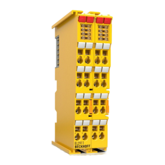
- Page 1 Operating Instructions | EN EL2911 and EL2911-2200 TwinSAFE Potential Supply Terminal with 4 digital fail-safe inputs 2023-03-08 | Version: 2.0.0...
-
Page 3: Table Of Contents
General safety instructions...................... 13 2.3.1 Before operation....................... 13 2.3.2 In operation ........................ 13 2.3.3 After operation........................ 13 3 System description .......................... 14 The Beckhoff EtherCAT Terminal system .................. 14 3.1.1 EtherCAT Bus Coupler..................... 15 3.1.2 EtherCAT Terminals...................... 16 3.1.3 E-bus.......................... 17 3.1.4 Power contacts......................... - Page 4 Inserting a Bus Coupler.................... 38 5.3.2 Inserting a Bus Terminal .................... 38 5.3.3 Adding an EL2911...................... 38 5.3.4 EL2911: using the integrated TwinSAFE Logic functions .......... 39 5.3.5 Address settings on TwinSAFE terminals with 1023 possible addresses...... 41 5.3.6 Alias devices ........................ 42 5.3.7 EL2911 parameters in TwinCAT ..................
-
Page 5: Notes On The Documentation
Notes on the documentation Disclaimer Beckhoff products are subject to continuous further development. We reserve the right to revise the operating instructions at any time and without prior announcement. No claims for the modification of products that have already been supplied may be made on the basis of the data, diagrams and descriptions in these operating instructions. -
Page 6: Limitation Of Liability
Modifications and changes to the hardware and/or software configuration that go beyond the documented options are prohibited and nullify the liability of Beckhoff Automation GmbH & Co. KG. The following is excluded from the liability: •... -
Page 7: Documentation Issue Status
The original documentation is written in German. All other languages are derived from the German original. Product features Only the product properties specified in the current operating instructions are valid. Further information given on the product pages of the Beckhoff homepage, in emails or in other publications is not authoritative. EL2911 and EL2911-2200 Version: 2.0.0... -
Page 8: Version History Of The Twinsafe Product
Date Software ver- Hardware Modifications sion version First release of the EL2911-2200 16/08/2018 First release of the EL2911 Staff qualification These operating instructions are intended exclusively for trained specialists in control technology and automation with the relevant knowledge. The trained specialist personnel must ensure that the applications and use of the described product meet all safety requirements. -
Page 9: Safety And Instruction
Notes are used for important information on the product. The possible consequences of failure to observe these include: • Malfunctions of the product • Damage to the product • Damage to the environment Information This sign indicates information, tips and notes for dealing with the product or the software. EL2911 and EL2911-2200 Version: 2.0.0... -
Page 10: Beckhoff Support And Service
The employees support you in the programming and commissioning of sophisticated automation systems. Hotline: +49 5246/963-157 E-mail: support@beckhoff.com Web: www.beckhoff.com/support Training Training in Germany takes place in our training center at the Beckhoff headquarters in Verl, at subsidiaries or, by arrangement, at the customer's premises. Hotline: +49 5246/963-5000 E-mail: training@beckhoff.com Web: www.beckhoff.com/training... -
Page 11: For Your Safety
Products marked with a crossed-out waste bin must not be disposed of with domestic waste. The device is considered waste electrical and electronic equipment when it is disposed of. Observe the national regulations for the disposal of waste electrical and electronic equipment. EL2911 and EL2911-2200 Version: 2.0.0... -
Page 12: Safety Image Signs
For your safety Safety image signs On Beckhoff products you will find attached or lasered safety pictograms, which vary depending on the product. They serve to serve to ensure safety for people and to prevent damage to the products. Safety pictograms must not be removed and must be legible for the user. -
Page 13: General Safety Instructions
De-energize and switch off components before working on them Check all safety-relevant equipment for functionality before working on the TwinSAFE component. Secure the working environment. Secure the machine or plant against being inadvertently started up. Observe the chapter Decommissioning [} 56]. EL2911 and EL2911-2200 Version: 2.0.0... -
Page 14: System Description
System description The Beckhoff EtherCAT Terminal system The Beckhoff EtherCAT Terminal system is used for decentralized connection of sensors and actuators to a controller. The components of the Beckhoff EtherCAT Terminal system are mainly used in industrial automation and building management systems. As a minimum, a bus station consists of an EtherCAT Coupler and connected EtherCAT Terminals. -
Page 15: Ethercat Bus Coupler
Fig. 2: Bus Coupler (EtherCAT) Connection technology Bus Coupler Wiring Spring-loaded system Connection cross-section 0.08 mm² ... 2.5 mm², stranded wire, solid wire Fieldbus connection EtherCAT Power contacts 3 spring contacts Current load 10 A Nominal voltage 24 V EL2911 and EL2911-2200 Version: 2.0.0... -
Page 16: Ethercat Terminals
Bus Terminal Wiring Spring-loaded system Connection cross-section typically 0.08 mm² – 2.5 mm², stranded wire, solid wire Communication E-bus Power contacts Up to 3 blade/spring contacts Current load 10 A Nominal voltage Depending on terminal type (typically 24 V Version: 2.0.0 EL2911 and EL2911-2200... -
Page 17: E-Bus
3.2.1 The I/O construction kit is extended safely The integrated TwinSAFE safety solution is the logical continuation of the open, PC-based Beckhoff control philosophy. Due to their modularity and versatility, the TwinSAFE components fit seamlessly into the Beckhoff control system. The I/O components are available in the formats Bus Terminal, EtherCAT Terminal, EtherCAT plug-in module and EtherCAT Box. -
Page 18: The Fail-Safe Principle (Fail Stop)
The basic rule for a safety system such as TwinSAFE is that failure of a part, a system component or the overall system must never lead to a dangerous condition. CAUTION Safe state! The safe state of the TwinSAFE system is always the switched-off and de-energized state. Version: 2.0.0 EL2911 and EL2911-2200... -
Page 19: Product Description
Product description EL2911 and EL2911-2200 The EL2911 is a safe potential feed terminal for the power contacts for a downstream potential group. In addition, it has 4 fail-safe inputs for sensors with potential-free contacts for 24 V The EP2911 meets the requirements of IEC 61508:2010 SIL 3 and EN ISO 13849-1:2015 (Cat 4, PL e). The safe inputs of the EL2911 meet the requirements of EN 62061:2005/A2:2015 to SILCL3, the safer output up... -
Page 20: Intended Use
. Failure to observe this can result in a loss of safety. WARNING Commissioning test Before the EL2911 can be used for the safety task, the user must carry out a commissioning test so that sensor and actuator wiring errors can be ruled out. Version: 2.0.0... - Page 21 Note on approval according to EN 81-20, EN 81-22 and EN 81-50 • The release does not apply to the EL1918-2200, EL2911-2200 and EP1957-2222 variants. • The TwinSAFE components may only be used in machines that have been designed and installed in accordance with the requirements of the EN 60204-1 standard.
-
Page 22: Requirements For The Potential Group
CAUTION Interference-free EtherCAT Terminals In the potential group connected through the EL2911, only interference-free standard terminals must be used. A list of the interference-free EtherCAT Terminals can be found in the Beckhoff Information System under http://infosys.beckhoff.de NOTE Maximum achievable safety level for the safe output... -
Page 23: Fig. 6 Protected Wiring
All conductors connected to the non-safe standard terminals are permanently installed and protected from external damage, e.g. through a cable duct or an armored conduit. CAUTION Fault exclusion The machine manufacturer or the user is solely responsible for the correct execution and evaluation of the applied alternatives. EL2911 and EL2911-2200 Version: 2.0.0... -
Page 24: Technical Data
In switched-off state, external feeds are detected above 5 V. Input process image 6 bytes Output process image 6 bytes EL2911 supply voltage (PELV) 24 V (–15% / +20%) Signal voltage "0" inputs -3 V to 5 V (EN 61131-2, type 3) see chapter Characteristic curve of the inputs [} 25] Signal voltage "1"... -
Page 25: Safety Parameters
NOTE Safe inputs in Cat.4 / PL e If two safe input channels in category 4 structure are to be used, any of the EL2911 channels can be used. Characteristic curve of the inputs The characteristic curve of the inputs is similar to type 3 according to EN 61131-2. -
Page 26: Dimensions
Product description Fig. 7: Characteristic curve of the inputs Dimensions Fig. 8: EL2911 dimensions Width: 24 mm (side-by-side installation) Height: 100 mm Depth: 68 mm Version: 2.0.0 EL2911 and EL2911-2200... -
Page 27: Operation
Please ensure that the digital TwinSAFE components are only transported and stored under the specified environmental conditions (see technical data). 5.2.3 Mechanical installation WARNING Risk of injury! Bring the bus system into a safe, de-energized state before starting installation, disassembly or wiring of the devices! EL2911 and EL2911-2200 Version: 2.0.0... -
Page 28: Fig. 9 Spring Contacts Of Beckhoff I/O Components
• Each bus station must be terminated on the right side with the EL9011 or EL9012 end cap to ensure the protection class and ESD protection. Fig. 9: Spring contacts of Beckhoff I/O components 5.2.3.2 Control cabinet / terminal box The TwinSAFE terminals must be installed in a control cabinet or terminal box with IP54 protection class according to IEC 60529 as a minimum. -
Page 29: Fig. 10 Installation Position And Minimum Distances
The key parameter is always the maximum permitted internally measured temperature of 110°C, above which the TwinSAFE components switch to safe state and report an error. The internal temperature can be read from the TwinSAFE components via CoE. EL2911 and EL2911-2200 Version: 2.0.0... - Page 30 EtherCAT Coupler or the power supply terminal with high E-bus load. The additional external heating of the TwinSAFE terminals by the adjacent power supply units increases the internal terminal temperature, which can lead to the maximum permissible temperature being exceeded. This leads to the diagnosis message "Overtemperature". Version: 2.0.0 EL2911 and EL2911-2200...
-
Page 31: Fig. 11 Thermally Unfavorable Arrangement Of The Twinsafe Terminals
The following arrangement is thermally optimized, as terminals with low current consumption and therefore low waste heat are attached between the EtherCAT Coupler/power supply terminal and terminals with higher waste heat. Fig. 12: Thermally favorable arrangement of the TwinSAFE terminals EL2911 and EL2911-2200 Version: 2.0.0... -
Page 32: Fig. 13 Installation On The Mounting Rail
For fastening mounting rails with a height of 7.5 mm under the terminals and couplers, use flat fastening components such as countersunk head screws or blind rivets. Version: 2.0.0 EL2911 and EL2911-2200... -
Page 33: Electrical Installation
(e.g. analog Bus Terminals or digital 4-channel Bus Terminals) do not or not fully loop through the power contacts. Potential supply terminals (EL91xx, EL92xx) interrupt the power contacts and thus represent the start of a new supply rail. EL2911 and EL2911-2200 Version: 2.0.0... -
Page 34: Fig. 15 Pe Power Contact
The PE power contact must not be used for other potentials! 5.2.4.2 Overvoltage protection If protection against overvoltage is necessary in your plant, provide a surge filter for the voltage supply to the Bus Terminal blocks and the TwinSAFE terminals. Version: 2.0.0 EL2911 and EL2911-2200... -
Page 35: Fig. 16 Connection Of A Cable To A Terminal Point
Wire size width (single core wires) 0.08 ... 2.5 mm Wire size width (fine-wire conductors) 0.08 ... 2.5 mm Wire size width (conductors with a wire end sleeve) 0.14 ... 1.5 mm Wire stripping length 8 ... 9 mm EL2911 and EL2911-2200 Version: 2.0.0... -
Page 36: Fig. 17 El2911 - Pin Assignment
Operation 5.2.4.4 Connection Fig. 17: EL2911 - pin assignment Terminal point Input / Out- Signal Input 1+ (clock output) Input 1- (safe input) Input 3+ (clock output) Input 3- (safe input) Input 2+ (clock output) Input 2- (safe input) Input 4+ (clock output) Input 4- (safe input) 1‘... -
Page 37: Fig. 18 Cable Routing
The common routing of signals together with other clocked signals in a common cable also reduces the maximum propagation, since crosstalk of the signals can occur over long cable lengths and cause diagnostic messages. EL2911 and EL2911-2200 Version: 2.0.0... -
Page 38: Configuration Of The Terminal In Twincat
See TwinCAT automation software documentation. 5.3.3 Adding an EL2911 An EL2911 is added in exactly the same way as any other Beckhoff EtherCAT Terminal. Open TwinSAFE Terminals item in the list and select the EL2911. Fig. 19: Adding an EL2911 Version: 2.0.0... -
Page 39: El2911: Using The Integrated Twinsafe Logic Functions
EL6910 documentation and the description of the function blocks under http:// www.beckhoff.de/german/download/twinsafe.htm. In order to be able to use the EL2911 again as a safe TwinSAFE I/O slave, please delete the logic, the mapping and the parameter data on the EtherCAT Terminal and switch the voltage off and on again. - Page 40 NOTE Project development TwinCAT 3.1 Build 4022.25 or newer is required to use the internal logic functions. If the EL2911 is used as TwinSAFE slave with the default project, at least an EL6910, EK1960 or newer logic component is required as TwinSAFE master.
-
Page 41: Address Settings On Twinsafe Terminals With 1023 Possible Addresses
TwinSAFE terminal. TwinSAFE addresses between 1 and 1023 are available. DIP switch Address 1023 WARNING TwinSAFE address Each TwinSAFE address may only be used once within a network / a configuration! The address 0 is not a valid TwinSAFE address! EL2911 and EL2911-2200 Version: 2.0.0... -
Page 42: Alias Devices
The alias devices are created in the safety project when the dialog is closed via OK. Alternatively, the user can create the alias devices individually. To this end select Add and New item from the context menu, followed by the required device. Version: 2.0.0 EL2911 and EL2911-2200... -
Page 43: El2911 Parameters In Twincat
Fig. 24: Creating alias devices by the user 5.3.7 EL2911 parameters in TwinCAT After creating the alias device, it can be parameterized according to the user specifications. The FSoE address is set under the Linking tab, and the link to the physical device is created. -
Page 44: Fig. 26 Connection Tab Of The Alias Device
Operation Fig. 26: Connection tab of the alias device The Safety Parameters tab contains the parameters of the EL2911 to be set. The output is parameterized via parameter 0x8000. The inputs are configured via the objects 0x8010 and 0x8011. Fig. 27: EL2911 parameters... - Page 45 Internal test pulses can have a length of up to 2 ms and cannot can be switched off. 8011:0B Channel4.DiagTestPulseFilterTime 0x0002 / 0.1 ms Input filter for the test pulse signal EL2911 and EL2911-2200 Version: 2.0.0...
-
Page 46: El2911 Process Image
5.3.8 EL2911 process image The process image of the EL2911 consists 6 bytes of process data in the input and the output. Fig. 28: EL2911 process image The assignment of the individual signals in the safe data is listed in the following table. -
Page 47: Twinsafe Reaction Times
Sensor Input Comm Logic Comm Output Actuator with, for example ReactionTime Worst-case reaction time The worst case reaction time is the maximum time required to switch off the actuator in the case of an error. EL2911 and EL2911-2200 Version: 2.0.0... -
Page 48: Fig. 30 Worst-Case Reaction Time
This error is detected at the output following the expiry of the watchdog time and leads to the switch-off. This results in the following equation for the worst-case reaction: ReactionTime Comm Comm Actuator with, for example ReactionTime Version: 2.0.0 EL2911 and EL2911-2200... -
Page 49: Diagnosis
Operation Diagnosis 5.5.1 Status LEDs Fig. 31: EL2911 status and diagnostics LEDs Color Description Input 1 green Status display for the respective input and output Input 2 LED lights up: Input/output is set Input 3 LED not lit: Input/output is not set... -
Page 50: Flash Code Display
Both the control entries and the history itself can be found in the CoE object 0x10F3. The entry Newest Message (0x10F3:02) contains the subindex of 0x10F3, which contains the latest diagnostic message, e.g. 0x06 for diagnostic message 1. Index 10F3 Diagnosis History Index (hex) Name Meaning Data type Flags Default 10F3:0 Diagnosis History Version: 2.0.0 EL2911 and EL2911-2200... - Page 51 Describes the type of parameter 1 Bits 12 to 15 = Bits 0 to 11 = data type of parameter 1 0x0001 - BOOLEAN 0x0002 - INT8 0x0003 - INT16 0x0004 - INT32 0x0005 - UINT8 EL2911 and EL2911-2200 Version: 2.0.0...
-
Page 52: Diag History Tab
Diag History tab. Use the Update History button to fetch the current data from the TwinSAFE component. Errors within the logic, the function blocks, the connections or the component itself are stored with a corresponding time stamp. Version: 2.0.0 EL2911 and EL2911-2200... -
Page 53: Fig. 34 Diag History
Messages with the Error status are not saved in the diag history Emergency In addition to saving the message in the diag history, an emergency object is also sent and displayed in the TwinCAT logger window. Overwrite / Acknowledge Mode This setting is currently not supported. EL2911 and EL2911-2200 Version: 2.0.0... -
Page 54: Service Life
YY: Year of manufacture Year: 2011 SW: Software version Software version: 05 HW: Hardware version Hardware version: 00 In addition the TwinSAFE terminals bear a unique serial number. 00000000 17110500 Fig. 36: Unique serial number of a TwinSAFE terminal Version: 2.0.0 EL2911 and EL2911-2200... -
Page 55: Maintenance And Cleaning
Cleaning by the manufacturer only Do not operate the TwinSAFE component if it is impermissibly dirty according to protection class IP20. Send impermissibly dirty TwinSAFE components to the manufacturer for cleaning. TwinSAFE components are basically maintenance-free. EL2911 and EL2911-2200 Version: 2.0.0... -
Page 56: Decommissioning
In accordance with the WEEE-2012/19/EU directives, you can return used devices and accessories for professional disposal. The transport costs are borne by the sender. Send the used devices with the note "For disposal" to: Beckhoff Automation GmbH & Co. KG Gebäude „Service“ Stahlstraße 31... -
Page 57: Appendix
If this data is confidential, the scrapping of the product after usage is recommended to protect this data. EL2911 and EL2911-2200 Version: 2.0.0... -
Page 58: Focus Of Certificates
(ELxxxx-abcd). This is applicable for all components like EtherCAT Terminals, EtherCAT Boxes, EtherCAT plug-in modules and Bus Terminals. If you regard the example EL1918 in the picture, the certificate is valid for both the EL1918 and the available variant EL1918-2200. Version: 2.0.0 EL2911 and EL2911-2200... -
Page 59: Certificate
Appendix Certificate Fig. 37: EL2911 EC Declaration of Conformity EL2911 and EL2911-2200 Version: 2.0.0... - Page 60 Slot and key system and screwless (spring-loaded) connection system ........Fig. 2 Bus Coupler (EtherCAT) ......................Fig. 3 Overview of EtherCAT Terminals....................Fig. 4 EL2911 - TwinSAFE potential feed terminal with 4 fail-safe inputs..........Fig. 5 External load ..........................Fig. 6 protected wiring..........................Fig. 7 Characteristic curve of the inputs....................
- Page 62 More Information: www.beckhoff.com/EL2911 Beckhoff Automation GmbH & Co. KG Hülshorstweg 20 33415 Verl Germany Phone: +49 5246 9630 info@beckhoff.com www.beckhoff.com...
Need help?
Do you have a question about the EL2911 and is the answer not in the manual?
Questions and answers