Beckhoff XTS Operating Instructions Manual
Linear product transport
Hide thumbs
Also See for XTS:
- Startup manual (46 pages) ,
- Operating instructions manual (209 pages) ,
- Operating instructions manual (126 pages)

Related Manuals for Beckhoff XTS


Summary of Contents for Beckhoff XTS
- Page 1 Operating Instructions | EN Linear product transport 2024-08-14 | Version 4.0.0...
-
Page 3: Table Of Contents
3.2.1 Motor module .......................... 23 3.2.2 Motor module with integrated NCT functionality..............24 3.2.3 NCT electronics ........................25 BIC | Beckhoff Identification Code ..................... 26 3.3.1 BIC as DataMatrix code ......................26 3.3.2 Scanning the DataMatrix code ....................27 3.3.3 Coded information on the BIC ....................27 Type key............................. - Page 4 Table of contents 3.6.4 Mover ............................48 3.6.5 NCT electronics ........................51 Special geometries..........................52 Track Management ..........................54 3.8.1 Requirements .......................... 54 3.8.2 Technical data ......................... 57 3.8.3 Application examples ......................58 NCT | No Cable Technology ......................59 3.9.1 Requirements ..........................
- Page 5 Table of contents 8.1.4 Last module of an infeed line ....................140 Mounting the modules........................140 8.2.1 Straight modules with connection cables ................141 8.2.2 Straight modules with connector ..................... 142 8.2.3 Straight modules, top ......................143 8.2.4 Straight modules, bottom ......................146 8.2.5 Curved segments ........................
- Page 6 Table of contents 12 Maintenance work on the mover........................ 197 12.1 Roller replacement at AT9011-0050-x550 ..................198 12.1.1 Scope of supply........................200 12.1.2 Preparation..........................201 12.1.3 Arrangement of the guide rollers on the mover ............... 201 12.1.4 Disassembly ..........................202 12.1.5 Mounting..........................
- Page 7 Table of contents 13.2 Adapter for cables ..........................263 13.3 Module connector cards........................263 13.4 Alignment gauge ..........................263 13.5 Rail on support ........................... 264 13.6 End caps ............................264 13.7 ESD brushes ............................264 13.8 Roller set ............................265 13.9 Torx key T20 ............................
-
Page 8: Documentation Notes
Documentation notes 1 Documentation notes 1.1 Disclaimer Beckhoff products are subject to continuous further development. We reserve the right to revise the documentation at any time and without notice. No claims for the modification of products that have already been supplied may be made on the basis of the data, dia- grams, and descriptions in this documentation. -
Page 9: Limitation Of Liability
• Use of untrained personnel • Use of unauthorized spare parts 1.1.4 Copyright © Beckhoff Automation GmbH & Co. KG, Germany The copying, distribution and utilization of this document as well as the communication of its contents to others without express autho- rization is prohibited. -
Page 10: Version Numbers
Product features The valid product features are always those specified in the current documentation. Further information given on the product pages of the Beckhoff homepage, in emails or in other publications is not au- thoritative. 1.3 Scope of the documentation... -
Page 11: Staff Qualification
Documentation notes 1.4 Staff qualification This documentation is aimed at trained specialists working in control technology and automation who have knowledge of the applicable and required standards and directives. Specialists must have knowledge of drive technology and electrical equipment as well as knowledge of safe working on electrical sys- tems and machines. - Page 12 Documentation notes Qualified electricians Qualified electricians have comprehensive technical knowledge gained from a course of study, an apprenticeship or technical train- ing. They have an understanding of control technology and automa- tion. They are familiar with relevant standards and directives. Quali- fied electricians can: •...
-
Page 13: Safety And Instruction
Documentation notes 1.5 Safety and instruction Read the contents that are related to the activities you will perform with the product. Always read the For your safety chapter in the doc- umentation. Observe the warning notes in the chapters so that you can handle the product and work with it properly and safely. - Page 14 Required accessories [+] This symbol shows the accessories required for the following steps. The accessories are not included in the scope of delivery and can be ordered from Beckhoff. Assembly material required This symbol shows the assembly material required for the following steps.
-
Page 15: Beckhoff Services
+49 5246 963-157 support@beckhoff.com www.beckhoff.com/en-en/support/our-support-services/ 1.7.2 Training offerings Training in Germany takes place at the Beckhoff branches or, after consultation, at the customer's premises. Beckhoff offers both face- to-face and online training courses. +49 5246 963-5000 training@beckhoff.com www.beckhoff.com/en-en/support/training-offerings/ 1.7.3 Service offerings... -
Page 16: Headquarters Germany
Hülshorstweg 20 33415 Verl, Germany +49 5246 963-0 info@beckhoff.com www.beckhoff.com/en-en/ A detailed overview of the Beckhoff locations worldwide can be found at: www.beckhoff.com/en-en/company/global-presence/ 1.7.5 Downloadfinder In the Download finder you will find configuration files, technical doc- umentation and application reports to download. -
Page 17: For Your Safety
For your safety 2 For your safety Read this chapter containing general safety information. The chap- ters in these operating instructions also contain warning notices. Al- ways observe the safety instructions for your own safety, the safety of other persons and the safety of the product. When working with control and automation products, many dangers can result from careless or incorrect use. -
Page 18: During Operation
Ensure that the protective conductor is properly connected. Never disconnect electrical connections while they are live. Only work on the XTS when the voltage has dropped to < 10 V. Disconnect all components from the mains and secure against reconnection. -
Page 19: Product Overview
Product overview 3 Product overview Position Name Curved rail Straight guide rail with lock Mover Lock Name plate Machine bed Straight guide rail without lock Straight module Curved segment Version: 4.0.0 ───... -
Page 20: Nct Electronics
Product overview 3.1 NCT electronics 3.1.1 For mover AT9014-1070-x550 Position Name 2 x 9 NCT electronics connection strip Fastening screw M6 x 25 Power LED Communication LED LED 1 Use input and output, adjustable LED 2 Diagnostic data available, adjustable ───... -
Page 21: For Third-Party Movers
Product overview 3.1.2 For third-party movers Position Name 2 x 9 NCT electronics connection strip Power LED Communication LED LED 1 Use input and output, adjustable LED 2 Diagnostic data available, adjustable Fastening screw M4 x 25 Adjusting screw for the air gap Version: 4.0.0 ───... - Page 22 Product overview 2 x 9 NCT electronics connection strip The NCT electronics for mover AT9014-1070-x550 and for third- party movers has a 2 x 9 connector strip. 18 16 10 8 Position Name Digital input 1 Digital input 3 / analog input 1 Digital input 2 Digital input 4 / analog input 2 Digital output 1 Digital output 3 Digital output 2...
-
Page 23: Name Plate
3.2 Name plate 3.2.1 Motor module Huelshorstweg 20 Phone: + 495246/963 - 0 AT2000-0250-0002 D-33415 Verl www.beckhoff.com Germany info@beckhoff.com XTS motor modul Automation GmbH & Co. KG Lot No.: 41230502 Rev No.: 00220018 0000a8kx Made in Germany Position Name Product designation... -
Page 24: Motor Module With Integrated Nct Functionality
Product overview 3.2.2 Motor module with integrated NCT functionality The name plate of motor modules with integrated NCT functionality is divided into two parts. AT2100-0250-0002 XTS motor module Lot No.: 20200502 Rev No.: 0022001800xx 0000a8kx Position Designation Date of manufacture - week/year... -
Page 25: Nct Electronics
Product overview 3.2.3 NCT electronics AT8200-1000-0100 NCT electronics 0000a8kx Lot No.: 11240101 Position Name Product designation CE conformity Date of manufacture - week/year Firmware and hardware revision BTN - Beckhoff Traceability Number WEEE compliance DataMatrix code Version: 4.0.0 ───... -
Page 26: Bic | Beckhoff Identification Code
3.3.1 BIC as DataMatrix code The Beckhoff Identification Code is displayed in the form of a Data- Matrix code and can be read with a scanner or smartphone. /963 - 0... -
Page 27: Scanning The Datamatrix Code
A scanner or smartphone is required to scan the DataMatrix code. Some smartphones support scanning the DataMatrix code with the camera. If scanning is not supported by your camera, Beckhoff rec- ommends the following reader apps: • Qrafter for IOS •... - Page 28 Product overview Position Explanation Data identi- Maxi- Example fier mum dig- Beckhoff order number 1P237452 BTN - Beckhoff Traceability Number SBTN SBTN0000k9ke Unique serial number Article name 1KAT9014-0070-0550 Quantity Quantity in sales unit Batch number 2P004323 May contain product information such as the year and week of production.
-
Page 29: Type Key
Product overview 3.4 Type key 3.4.1 Motor modules AT2abb-0ccc-000d Explanation Product area • AT = drive technology Product type • 20 = Standard motor module • 21 = Motor module with integrated NCT functionality Module variant • 00 = straight •... -
Page 30: Guide Rails
Product overview 3.4.2 Guide rails AT 9abb–cccc–00dd Explanation Product area • AT = drive technology Product type • 0 = without lock • 1 = with lock Rail variants • 00 = straight • 20 = 22.5° curved segment • 25 = - 22.5° curved segment •... -
Page 31: Mover
Product overview 3.4.3 Mover AT 901a-b0cc-en50 Explanation Product area • AT = drive technology Product type • 901 = mover Roller variants • 1 = mover, 6 rollers • 2 = mover, 12 rollers • 4 = mover, 6 rollers, 2 of which are spring-loaded Design •... -
Page 32: Product Characteristics
Software-based control The XTS is controlled by a software-based cascade control. The control loop structure is stored in the XTS drivers and is calculated cyclically on the control IPC. No additional drive software is re- quired. Programming according to The standardized Motion Control function blocks according to the IEC 61131-3... -
Page 33: Components
3.6.1 Motor modules Use cables with a high number of bending cycles For moving track sections, cables with a high number of bending cy- cles must be used. Beckhoff recommends the use of the following cables: • ZK7A14-3155-Axxx • ZK7A14-3031-Axxx A system consists of individual motor modules that can be combined to form a complete drivetrain. - Page 34 Product overview Straight, with connection cables for infeed AT2001-0250 The straight module AT2001-0250 has a length of 250 mm and con- nection cables for infeed. It is suitable for building a straight track section. 6/963 - + 49524 Phon e: weg 20 off.co m Huels horst www.
- Page 35 Product overview AT2002-0250 The straight module AT2002-0250 has a length of 250 mm and a 180° rotatable connector for infeed. Cables with drag chain capabil- ity [+] in variable lengths can be connected to the connector. • UL-certified 6/963 - Phon e: + 49524 weg 20 off.co m...
- Page 36 Product overview -22.5° curved segment, without infeed AT2025-0250 The module AT2025-0250 has a length of 250 mm. It represents a -22.5° curved segment of a circle with a diameter of 1273 mm. • UL-certified It is not possible to install two 22.5° curved segments one behind the other.
- Page 37 Verl info@be ckhoff.c German Co. KG Automa tion GmbH & AT2 0 0-02 r mod ul XTS moto 4123 0502 Lot No.: 0022 0018 Rev No.: Germa ny Made in 0000a 8kx AT2050-0500-0001 The module AT2050-0500-0001 has a length of 500 mm and the op- tion for additional cooling.
- Page 38 Product overview Straight, with integrated NCT functionality, with connector for infeed AT2102-0250 The straight module AT2102-0250 has a length of 250 mm, inte- grated NCT functionality and a 180° rotatable connector. Cables with drag chain capability [+] in variable lengths can be connected to the connector.
-
Page 39: Motor Modules For Parallel Guide Rails
3.6.2 Motor modules for parallel guide rails Use cables with a high number of bending cycles For moving track sections, cables with a high number of bending cy- cles must be used. Beckhoff recommends the use of the following cables: • ZK7A14-3155-Axxx •... - Page 40 Product overview Straight, with connection cables for infeed AT2001-0250-0002 The straight module AT2001-0250-0002 has a length of 250 mm and connection cables for infeed. It is suitable for building a straight track section. 6/963 - + 49524 Phon e: weg 20 off.co m Huels horst www.
- Page 41 Product overview AT2002-0250-0002 The straight module AT2002-0250-0002 has a length of 250 mm and a 180° rotatable connector for infeed. Cables with drag chain capability [+] in variable lengths can be connected to the connector. • UL-certified 6/963 - Phon e: + 49524 weg 20 off.co m...
- Page 42 Product overview -22.5° curved segment, without infeed AT2025-0250-0002 The module AT2025-0250-0002 has a length of 250 mm. It repre- sents a -22.5° curved segment of a circle with a diameter of 1273 mm. • UL-certified 6/963 - + 49524 Phon e: weg 20 off.co m Huels horst...
- Page 43 German Co. KG -000 2 Automa tion GmbH & AT2 0 0-02 r mod ul XTS moto 4123 0502 Lot No.: 0022 0018 Rev No.: Germa ny Made in 0000a 8kx AT2050-0500-0005 The module AT2050-0500-0005 has a length of 500 mm and the op- tion for additional cooling.
- Page 44 Product overview Straight, with integrated NCT functionality, with connector for infeed AT2102-0250-0002 The straight module AT2102-0250-0002 has a length of 250 mm, in- tegrated NCT functionality and a 180° rotatable connector. Cables with drag chain capability [+] in variable lengths can be connected to the connector.
-
Page 45: Guide Rails
Product overview 3.6.3 Guide rails In addition to the motor modules you need a rail system, which con- sists of various guide rails. The guide rails for mounting on the mod- ules are available in different versions: Straight, without lock AT9000-xxxx Straight guide rails without lock are available in eleven lengths: •... - Page 46 Product overview -22.5° curved segment AT9025-1466-0xxx The guide rail AT9025-1466-0xxx is available with a -22.5° angle. The assembly of this rail is possible with a combination of a straight module with -22.5° curved segment AT2025-0250 AT2026-0250. 45° curved segment, 90° curve AT9040-0750-00xx The guide rail AT9040-0750-00xx is suitable for the combination of a straight module with two consecutive 45°...
- Page 47 Product overview 180° curved segment, without lock AT9050-0500-0055 The guide rail AT9050-0500-0055 enables a tight 180° curve and is available to match the motor module AT2050-0500. This guide rail was specially designed for the mover AT9014-0055- x550 with 2 spring-loaded rollers. 180°...
-
Page 48: Mover
Product overview 3.6.4 Mover The movers are mounted on the guide rails and are available in the following variants: Mover, length 70 mm, with mounted NCT electronics AT8300-1100-0100 The mover AT8300-1100-0100 with a length of 70 mm has mounted NCT electronics and has four guide rollers and two spring-loaded guide rollers. - Page 49 Product overview AT9012-0050-0550 The mover AT9012-0050-0550 with a length of 50 mm has twelve guide rollers. The magnetic plate set AT9001-0550 is mounted. B E C K H O F AT9012-0050-1550 The mover AT9012-0050-1550 with a length of 50 mm has twelve guide rollers.
- Page 50 Product overview Mover, length 70 mm AT9011-0070-0550 The mover AT9011-0070-0550 with a length of 70 mm has six guide rollers. The magnetic plate set AT9001-0550 is mounted. AT9011-0070-1550 The mover AT9011-0070-1550 with a length of 70 mm has six guide rollers. The magnetic plate set AT9001-1550 is mounted. AT9014-0070-0550 The mover AT9014-0070-0550 with a length of 70 ...
-
Page 51: Nct Electronics
Product overview AT9014-1070-0550 The mover AT9014-1070-0550 with a length of 70 mm is suitable for mounting the NCT electronics AT8200-1000-0100 [+] and has four guide rollers and two spring-loaded guide rollers. The magnetic plate set AT9001-0550 is mounted. AT9014-1070-1550 The mover AT9014-1070-1550 with a length of 70 mm is suitable for mounting the NCT electronics AT8200-1000-0100 ... -
Page 52: Special Geometries
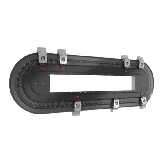
Product overview 3.7 Special geometries Special geometries can be realized with the XTS system by using the 233 mm and 249 mm long motor modules. Systems with moving sections can be configured in the shape of an L, U, O or Z by com- bining curved segments with different radii and straight modules with different lengths. - Page 53 Product overview O shape Z shape Version: 4.0.0 ───...
-
Page 54: Track Management
XTS Tracks An XTS Track is a route that can be used by movers and consists of one or more parts. A part can also occur more than once in a partic- ular track or be inserted in several different tracks. - Page 55 Examples of the air gap AT200 -02 Huelshorstweg 20 Phone: + 495246/963 - 0 D-33415 Verl www.beckhoff.com XTS motor modul Automation GmbH & Co. KG Germany info@beckhoff.com Lot No.: 20200502 Rev No.: 00220018...
- Page 56 D-3341 Germa ny Co. KG GmbH & Autom ation -02 50 AT2 00 or mod ul XTS mot 4123 0502 Lot No.: 0022 0018 Rev No.: Germ any Made in 0000a 8kx An end plug [2] must be inserted into the last module [1] of an infeed line to prevent the ingress of dust and liquids.
-
Page 57: Technical Data
Torques of the linear axes [Nm] Offset to direction of travel* [mm] Lateral ≤ 0.1 In height ≤ 0.1 * When using a Beckhoff guide rail Maximum linear axis torque* [Nm] X-axis Mx Y-axis My Z-axis Mz Drive axis * When using a Beckhoff guide rail Air gap in the direction of travel [mm]... -
Page 58: Application Examples
Product overview 3.8.3 Application examples XTS Track Management can be used for the following applications, for example: • Input and removal of movers without interrupting the product flow • Product buffer through the arrangement of several track sections above one another •... -
Page 59: Nct | No Cable Technology
Product overview 3.9 NCT | No Cable Technology The XTS function extension with No Cable Technology is part of the XTS software package TF5850 | TwinCAT 3 XTS. Special motor modules with NCT functionality provide a contactless, continuous power supply and synchronous real-time data transmis- sion to the movers with NCT electronics installed, enabling the inte- gration of sensors and actuators on the movers. -
Page 60: Requirements
Product overview 3.9.1 Requirements For NCT, you need at least one motor module with integrated NCT functionality and a mover with NCT electronics installed to enable data transmission between the motor module and the mover. A suit- able tool is also required on the mover. ───... -
Page 61: Technical Data
Further information can be found in chapter "Curved segments", [Page 147], "Motor modules", [Page 33] and "Straight modules with connector", [Page 142]. Mover The following Beckhoff movers are approved for NCT: • AT8300-1x00 • AT9014-1070 with mounted NCT electronics AT8200-1000-0100 Further information can be found in chapter "Mover", [Page 48]. -
Page 62: Application Examples
Product overview 3.9.3 Application examples NCT can be used for the following applications, for example: • Aligning, picking up, placing and processing products • Sorting out faulty products with the help of mounted sliders • Weight determination, measurement and condition monitoring of products •... -
Page 63: Intended Use
The components must be installed in electrical systems or machines and may only be put into operation as integrated components of the system or machine. All components of the XTS are intended only to be programmed and commissioned with the help of the Beckhoff TwinCAT automation software. -
Page 64: Technical Data
Technical data 4 Technical data Below you will find definitions of terms, environmental conditions and operating specifications as well as technical data. 4.1 Definition All details relate to an ambient temperature of 25 °C. The data can have a tolerance of +/- 10 %. 4.1.1 Technical terms Nominal force F Nominal force that a mover can continuously apply. -
Page 65: Data For Operation And Environment
Operate the XTS only under the specified environmental condi- tions Operate the Beckhoff XTS only in accordance with the specifications for operation and the environment listed in this chapter. This en- sures a long service life and proper operation. -
Page 66: Electrical Data And System Properties
Power consumption per mover, 48 V [W] With a mass of 1 kg and peak acceleration of 50 m/s² * At values below 48 V not all nominal data can be achieved. Beckhoff recommends a power supply of 48 V System properties Typical thermal time constant t... -
Page 67: Motor Module With Integrated Nct Functionality
Technical data 4.3.1 Motor module with integrated NCT functionality NTC energy transfer System properties NTC nominal output [kW] ≤ 35 Depending on the mover position and the mover distances NCT peak power [W] ≤ 75 Depending on the mover position and the mover distances Output voltage [V Closed-loop Energy transfer... -
Page 68: Mechanical Data
Technical data 4.4 Mechanical data 4.4.1 Modules General housing properties Modules AT2xxx-0xxx IP protection rating IP65 In the assembled state for a closed system, only water- proof for a short time, not corrosion-resistant. Aluminum components anodized Board elements painted Color matt black Straight, without infeed Modules... - Page 69 Technical data 22.5° curved segment, with connection cables for infeed Modules AT2021-0250 Height [mm] 106.8 Depth [mm] 256.2 Weight without attachments [kg] Width on the machine bed [mm] 39.1 Upper width on the motor / guide [mm] 22.1 -22.5° curved segment, without infeed Modules AT2025-0250 Height [mm]...
- Page 70 Technical data 180° curved segment, without infeed Modules AT2050-0500 AT2050-0500-0001 Height [mm] 194.5 194.5 Depth [mm] 306.7 306.7 Weight without attachments [kg] Width on the machine bed [mm] 39.1 52.1 Upper width on the motor / guide [mm] 22.1 22.1 Straight, with integrated NCT functionality, without infeed Modules AT2100-0250 Height [mm]...
-
Page 71: Mover
Technical data 4.4.2 Mover Mover, length 70 mm, with mounted NCT electronics Mover AT8300-1x00 Length [mm] Number of rollers Weight [g] Without magnetic plate set. Weight [g] With mounted magnetic plate set AT9001-0550. Distance between the feedback flag and the motor 0.5 to 1.4 module [mm] Distance between NCT electronics and motor mod- 0.7 to 1.0... - Page 72 Technical data Mover, length 70 mm Mover AT9011-0070 Length [mm] Number of rollers Weight [g] Without magnetic plate set. Weight [g] With mounted magnetic plate set AT9001-0550. Distance between the feedback flag and the motor 0.5 to 1.4 module [mm] Mover AT9014-x070 Length [mm] Number of rollers Weight [g] Without magnetic plate set.
-
Page 73: Guide Rails
Technical data 4.4.3 Guide rails Straight AT9x00- 0250 0500 … 2500 Length of travel distance [mm] + 250 2500 Length [mm] 276.5 526.5 + 250 2526.5 Height [mm] Height on the module [mm] Depth [mm] 22.2 22.2 22.2 22.2 Weight [g] + 280 2780 22.5° curved segment AT9020- 1250-0055 1250-0170... -
Page 74: Cables
Technical data 45° curved segment, 90° curve AT9040- 0750-0055 0750-0170 Length of travel distance [mm] Length [mm] 625.4 625.4 Total height [mm] 406.1 406.1 Height on the module [mm] Depth [mm] 22.2 22.2 Weight [g] 45° curved segment, 180° curve AT9040- 1250-0070 Length of travel distance [mm] 1250 Length [mm] 625.4... -
Page 75: Dimensional Drawings
Technical data 4.5 Dimensional drawings Dimensional drawings and 3D models online You have the possibility to download the dimensional drawings and 3D models of the individual components from the Beckhoff website: www.beckhoff.com/en-en/support/download-finder/ 4.5.1 Modules All figures in millimeters Straight, without infeed AT2000-0233 •... - Page 76 Technical data AT2000-0250 • 250 mm • UL-certified ─── Version: 4.0.0...
- Page 77 Technical data Straight, with connection cables for infeed AT2001-0250 • 250 mm Version: 4.0.0 ───...
- Page 78 Technical data AT2001-0250-0003 • 250 mm • UL-certified ─── Version: 4.0.0...
- Page 79 Technical data Straight, with connector for infeed AT2002-0249, option • with connector for infeed, direction of rotation to name plate ZX2002-0002 • 249 mm • UL-certified Version: 4.0.0 ───...
- Page 80 Technical data AT2002-0249, option • with connector for infeed, direction of rotation to feedback sys- ZX2002-0001 • 249 mm • UL-certified ─── Version: 4.0.0...
- Page 81 Technical data AT2002-0250, option • with connector for infeed, direction of rotation to name plate ZX2002-0002 • 250 mm • UL-certified 250 - 0,3 ~ 15 Ø5 F6 (2x) M (3x) 39,1 80 ± 0,1 90 ± 0,1 28,7 83,6 90 ± 0,2 55,1 35 ±...
- Page 82 Technical data AT2002-0250, option • with connector for infeed, direction of rotation to feedback sys- ZX2002-0001 • 250 mm • UL-certified ~ 15 ± ± ± ± ± ─── Version: 4.0.0...
- Page 83 Technical data 22.5° curved segment, without infeed AT2020-0250 • UL-certified Version: 4.0.0 ───...
- Page 84 Technical data 22.5° curved segment, with connection cables for infeed AT2021-0250 ─── Version: 4.0.0...
- Page 85 Technical data AT2021-0250-0003 • UL-certified Version: 4.0.0 ───...
- Page 86 Technical data -22.5° curved segment, without infeed AT2025-0250 • UL-certified (278,05) 39,1 ─── Version: 4.0.0...
- Page 87 Technical data AT2026-0250-0003 (278,05) 39,1 Version: 4.0.0 ───...
- Page 88 Technical data 45° curved segment, without infeed AT2040-0250 • UL-certified ─── Version: 4.0.0...
- Page 89 Technical data 45° curved segment, with connection cables for infeed AT2041-0250 Version: 4.0.0 ───...
- Page 90 Technical data AT2041-0250-0003 • UL-certified (258,93) 30,2 12,2 45ƒ Ø5 F6 (2x) 110 ± 0,1 M5 (3x) ± 39,1 ─── Version: 4.0.0...
- Page 91 Technical data 180° curved segment, without infeed AT2050-0500 • UL-certified 194,5 ~ 13,5 20,8 (3x) 9,8 (3x) 96,8 ± 0,2 17,1 ± 0,1 9,7 - 0,1 39,1 Version: 4.0.0 ───...
- Page 92 Technical data AT2050-0500-0001 • UL-certified • with option for additional cooling 194,5 ~ 13,5 20,8 (3x) 9,8 (3x) 96,8 ± 0,2 17,1 ± 0,1 9,7 - 0,1 39,1 52,1 50,7 ± 0,2 48,6 ± 0,2 M4x10 (8x) 104,8 ± 0,2 ───...
- Page 93 Technical data Straight, with integrated NCT functionality, without infeed AT2100-0250 • 250 mm • with integrated NCT functionality Version: 4.0.0 ───...
- Page 94 Technical data Straight, with integrated NCT functionality, with connector for infeed AT2102-0250, option • with connector for infeed, direction of rotation to name plate ZX2002-0002 • 250 mm (51,7) -0,1 250 -0,3 (modular dimension 250) (51,2) M3 5 M3 5 8 (2x) Ø5 F6 (2x) 80 0,1 90 0,1...
- Page 95 Technical data AT2102-0250, option • with connector for infeed, direction of rotation to feedback sys- ZX2002-0001 • 250 mm Version: 4.0.0 ───...
-
Page 96: Guide Rails
Technical data 4.5.2 Guide rails All figures in millimeters Straight AT9x00-xxxx • different lengths from 249 to 2500 mm • for all Beckhoff movers AT9100-xxxx Bezeichnung Länge L [mm] Gewicht [g] Name Length L [mm] Weight [g] AT9x00-0250 AT9x00-0500 AT9x00-0750 AT9000-xxxx... - Page 97 Technical data 22.5° curved segment AT9020-1250-0xxx • Guide rail set, 1250 mm • for AT9014-00xx-x550 • consisting of: – 1 x AT9020-1250-1055 guide rail, suitable for 1 x straight mo- tor module AT200x-0250 and 2 x 22.5° motor module AT202x-0250 – 1 x AT9020-1250-2055 guide rail, suitable for 2 x 22.5° motor module AT202x-0250 Bezeichnung Länge L [mm]...
- Page 98 Technical data -22.5° curved segment AT9025-1466-0xxx • Guide rail set, 1466 mm • for AT9014-00xx-x550 • consisting of: – 1 x guide rail AT9025-1466-1170, suitable for 1 x straight mo- tor module AT200x-0233 and 2 x -22.5° motor module AT202x-0250 – 1 x AT9025-1466-2170 guide rail, suitable for 1 x straight mo- tor module AT200x-0233 and 2 ...
- Page 99 Technical data 45° curved segment AT9040-0750-00xx • Guide rail, 750 mm • for movers AT9011-0070-x550 and AT9014-0055 • suitable for 1 x straight motor module AT200x-0250 and 2 x 45° motor module AT204x-0250 Bezeichnung Länge L [mm] Gewicht [g] Name Length L [mm] Weight [g] AT9040-0750-0070 Version: 4.0.0...
- Page 100 Technical data AT9040-1250-0070 • Guide rail set, 1250 mm • for mover AT9011-0070-x550 • consisting of: – 1 x guide rail AT9040-1250-1070, suitable for 1 x motor mod- ule AT200x-0250 and 2 x 45° motor module AT204x-0250 – 1 x guide rail AT9040-1250-2070, suitable for 2 x 45° motor module AT204x-0250 3 8 4 , 7 7 5 4 , 6...
- Page 101 Technical data 180° curved segment AT9050-0500-0xxx • for AT9011-0070 and AT9014-0055 • suitable for 1 x 180° motor module AT2050-0500 Bezeichnung Länge L [mm] Gewicht [g] Name Length L [mm] Weight [g] AT90 0- 5 050 0-0 70 Version: 4.0.0 ───...
-
Page 102: Mover
Technical data 4.5.3 Mover All figures in millimeters Mover, length 70 mm, with mounted NCT electronics AT8300-1100-0100 • 6 guide rollers • Standard magnetic plate set ─── Version: 4.0.0... - Page 103 Technical data AT8300-1200-0100 • 6 guide rollers • Magnetic plate set Mover 1 Version: 4.0.0 ───...
- Page 104 Technical data Mover, length 50 mm AT9011-0050-0550 • 6 guide rollers • Standard magnetic plate set ─── Version: 4.0.0...
- Page 105 Technical data AT9011-0050-1550 • 6 guide rollers • Magnetic plate set Mover 1 Version: 4.0.0 ───...
- Page 106 Technical data AT9012-0050-0550 • 12 guide rollers • Standard magnetic plate set ─── Version: 4.0.0...
- Page 107 Technical data AT9012-0050-1550 • 12 guide rollers • Magnetic plate set Mover 1 Version: 4.0.0 ───...
- Page 108 Technical data Mover, length 55 mm AT9014-0055-0550 • 6 guide rollers, 2 of which are spring-loaded • Standard magnetic plate set ─── Version: 4.0.0...
- Page 109 Technical data AT9014-0055-1550 • 6 guide rollers, 2 of which are spring-loaded • Magnetic plate set Mover 1 Version: 4.0.0 ───...
- Page 110 Technical data Mover, length 70 mm AT9011-0070-0550 • 6 guide rollers • Standard magnetic plate set ─── Version: 4.0.0...
- Page 111 Technical data AT9011-0070-1550 • 6 guide rollers • Magnetic plate set Mover 1 Version: 4.0.0 ───...
- Page 112 Technical data AT9014-0070-0550 • 6 guide rollers, 2 of which are spring-loaded • Standard magnetic plate set ─── Version: 4.0.0...
- Page 113 Technical data AT9014-0070-1550 • 6 guide rollers, 2 of which are spring-loaded • Magnetic plate set Mover 1 Version: 4.0.0 ───...
- Page 114 Technical data Mover, length 70 mm, suitable for NCT electronics AT9014-1070-0550 • 6 guide rollers • Standard magnetic plate set 76,3 ± 34,6 ± center of gravitiy weight: approx. 674g ± ± ─── Version: 4.0.0...
- Page 115 Technical data AT9014-1070-1550 • 6 guide rollers • Magnetic plate set Mover 1 76,3 ± 34,6 ± center of gravitiy weight: approx. 674g ± ± Version: 4.0.0 ───...
-
Page 116: Nct Electronics
Technical data 4.5.4 NCT electronics All figures in millimeters AT8200-1000-0100 • for mover AT9014-1070-x550 Ø 3,95 (2x) Gewicht / weight: approx. 220 g 151,3 M6 (2x) Schwerpunkt / max. Anzugsdrehmoment / center of gravity max. tightening torque: 3 Nm ─── Version: 4.0.0... - Page 117 Technical data AT8200-2000-0100 • for third-party movers 21,8 Ø 3,95 (2x) 118,1 36,4 Schwerpunkt / center of gravity max. Anzugsdrehmoment / max. tightening torque: 3 Nm Gewicht / weight: approx. 230 g Einstellschraube für den Luftspalt, 2 mm Innensechskant-Schlüssel wird benötigt / Adjustment screw for air-gap, 2 mm hex driver required M4x25 ISO14580 TX20...
-
Page 118: Magnetic Plate Sets [+]
4.5.5 Magnetic plate sets [+] All figures in millimeters AT9001-0450-1640 • Standard magnetic plate set • 4-pin, 50 mm • for XTS movers and third-party movers AT9001-1450-1640 • Magnetic plate set Mover 1 • 4-pin, 50 mm • for XTS movers and third-party movers AT9001-0550-1640 •... - Page 119 Technical data AT9001-1550-1640 • Magnetic plate set Mover 1 • 5-pin, 50 mm • for XTS movers and third-party movers AT9001-0775-1640 • Standard magnetic plate set • 7-pin, 75 mm • for third-party movers AT9001-1775-1640 • Magnetic plate set Mover 1 • 7-pin, 75 mm •...
- Page 120 Technical data AT9001-0AA0-1640 • Standard magnetic plate set • 10-pin, 100 mm • for third-party movers AT9001-1AA0-1640 • Magnetic plate set Mover 1 • 10-pin, 100 mm • for third-party movers ─── Version: 4.0.0...
-
Page 121: Packaging
Packaging 5 Packaging The packaging contains the following handling instructions: The packaging and components must be transported, handled and stored in such a way that the arrows point upwards at all times. Protect from moisture The packaging and the components must be protected from high air humidity and must be stored under cover. -
Page 122: Esd Conductivity
Packaging Prohibited for people with metal implants The packaging contains components with magnetic fields. There is a risk for: • People with magnetically conducting implants Metal implants can be heated by magnetic fields. A safety distance of 250 mm from all magnetic parts applies. No direct contact with magnetic components in the vicinity of parts susceptible to interference is permitted. -
Page 123: Scope Of Supply
Check the scope of supply for missing or damaged parts Check your delivery for completeness. If any parts are missing or became damaged during transport, contact the carrier, manufacturer or Beckhoff Service immediately: service@beckhoff.com Depending on the order, the scope of delivery may consist of differ- ent components. - Page 124 Scope of supply • 3 x screw M4 x 40 AT9020-1250-0xxx • 2 x guide rail • 2 x nut M3 • 4 x locating pin D4 x 16 • 10 x locating pin D5 x 10 • 2 x screw M3 x 30 • 14 x screw M4 x 40 • 2 x washer AT9025-1466-0xxx • 2 x guide rail •...
-
Page 125: Mover
Scope of supply 6.3 Mover AT901x-x0xx-x550 • 1 x mover mounted with encoder flag 1.2 mm • 1 x encoder flag 1.0 mm • 1 x encoder flag 1.4 mm • 1 x encoder flag 1.6 mm • 1 x encoder flag 1.8 mm AT8300-1x00-0100 • 1 x mover mounted with encoder flag 1.2 mm •... -
Page 126: Transport And Storage
Transport and storage 7 Transport and storage NOTICE Avoid damage due to improper transportation and storage Observe the conditions for transportation and storage to prevent damage to the components. 7.1 Conditions Take care during transport and storage to avoid damage to individ- ual components. -
Page 127: Mechanical Installation
Mechanical installation 8 Mechanical installation Note system view The name plate in the figures is used for orientation in the following instructions. It helps you to be sure of the view from which you have to mount the components. 8.1 Preparation Required tools •... -
Page 128: Maintenance Concept
8.1.1 Maintenance concept Fast reaction in case of a module failure You have the option to assemble the XTS in such a way that you can replace individual infeed lines in case of a failure. As a result you do not have to dismantle the entire XTS system and you can minimize the downtime and maintenance work. - Page 129 The guide rails are connected to one another at the connectors and the modules are fixed to the machine bed. Detailed information on the assembly of a complete XTS system can be found in the follow- ing chapters of the mechanical installation.
-
Page 130: Modules
QR code or visit the following website: https://vimeo.com/913641582 Observe the order of assembly Assemble the XTS from the inside outwards. Insert straight modules first. Then insert curved segments and close the system. In this way, you avoid complications when positioning and mounting individual modules at the end of the mechanical installation. - Page 131 Mechanical installation Connector card With a connector card, one or more modules without infeed are con- nected with a module with infeed to form an infeed line. Each mod- ule without infeed must be connected to an infeed line via a connec- tor card.
- Page 132 Mechanical installation 8.1.2.2 Straight, with connection cables for infeed ► Insert short locating pins [1] and a long locating pin [2] into mod- ► Insert the seal [1] ─── Version: 4.0.0...
- Page 133 Mechanical installation 8.1.2.3 Straight, with connector for infeed ► Insert short locating pins [1] and a long locating pin [2] into mod- ► Insert the seal [1] Version: 4.0.0 ───...
- Page 134 Correct connector card for modules AT2100-0xxx Automation GmbH & Co. KG Automation GmbH & Co. KG Huelshorstweg 20 Phone: +495246/963 - 0 Huelshorstweg 20 Phone: +495246/963 - 0 D-33415 Verl www.beckhoff.com D-33415 Verl www.beckhoff.com Germany info@beckhoff.com Germany info@beckhoff.com Made in Germany...
- Page 135 The cut-out [1] must be located on the upper, outer edge of the con- nector card. The lettering XTS-Connector [2] must be on the side of the name plate. ► Insert connector card [1] at the position of the seal [2] 8.1.2.5...
- Page 136 Mechanical installation ► Insert the seal [1] 8.1.2.6 180° curved segments Mounting example For the mounting example of a simple symmetrical system with 180° curved segments, two curved segments must be prepared in the same way. ► Insert short locating pins [1] and a long locating pin [2] into mod- ►...
- Page 137 Mechanical installation Correct connector card for modules AT2050-0500 A connector card ZX2000-0100 [2] must be inserted into the mod- ules AT2050-0500 [1] to establish the connection between the mod- ules. The short connector card ZX2000-0200 [3] must not be inserted into the modules AT2050-0500 [1], as it does not protrude from the mod- ule and cannot establish a connection between the modules.
- Page 138 Mechanical installation ► Insert the screws [1] with washers [2] into the curved segment to a maximum depth of 4 mm < 4 ─── Version: 4.0.0...
-
Page 139: Guide Rails, 180° Curved Segment
Mechanical installation 8.1.3 Guide rails, 180° curved segment ► Insert locating pins [1] into the curved rail [2] Grease ► Grease the connecting surfaces [1] and inner running sur- faces [2] with petrolatum Version: 4.0.0 ───... -
Page 140: Last Module Of An Infeed Line
Mechanical installation 8.1.4 Last module of an infeed line An end plug must be inserted into the opening for the connector card in the last module of an infeed line to prevent dust and liquids from entering the module. Mounting the end plugs ►... -
Page 141: Straight Modules With Connection Cables
Mechanical installation Once all modules have been prepared, they are mounted on the machine bed in the following order. The mounting of the first module depends on whether you are using a module with connection cables or with a connector. 8.2.1 Straight modules with connection cables ►... -
Page 142: Straight Modules With Connector
Mechanical installation 8.2.2 Straight modules with connector NOTICE Limited number of turns The connector may be rotated up to ten times through 180° to bring it into a safe latching position. If you turn the connector more than ten times, the cables inside and the latching mechanism of the connector may be damaged and the connector may no longer be placed in a safe latching po- sition. -
Page 143: Straight Modules, Top
► Make sure that the connector card engages Mounting with alignment gauge [+] Mount modules with alignment gauge [+] Beckhoff recommends using the optional alignment gauge for mounting the straight modules AT2x0x-0250. If you are not using an alignment gauge, you can use a vernier caliper, for example. - Page 144 Mechanical installation Make sure that you place the alignment gauge correctly on the mod- ules. The alignment gauge must be flush with the outer edges of the modules and the marking [1] of the alignment gauge must be in the middle [2] above two modules. ►...
- Page 145 You can also mount the straight modules AT2x0x-0250 without an alignment gauge [+]. Beckhoff recommends using a vernier caliper for mounting the straight modules if you do not use the optional alignment gauge. If a vernier caliper is used, the distance from the outer edge of the first locating pin to the opposite edge of the first locating pin in the aligned module is 255 mm.
-
Page 146: Straight Modules, Bottom
Mechanical installation 8.2.4 Straight modules, bottom ► Position the module [1] with the locating pins [2] in the elongated holes of the machine bed [3] and secure it against falling out ► Hand-tighten the screw [1] with the washer [2] in the center of the module [3] ►... -
Page 147: Curved Segments
Huelshors Verl www.beck hoff.com D-33415 info@beck & Co. KG Germany n GmbH Automatio AT20 0-025 modu l XTS motor 41230 502 Lot No.: 00220 018 Rev No.: Made in German 0000a8k 3 - 0 tweg 20 Phone: + 495246/96 Huelshors www.beck... - Page 148 Phone: + 495246/9 Huelshors www.beck hoff.com D-33415 Verl info@bec khoff.com Germany & Co. KG n GmbH AT20 0-02 Automatio r modu l XTS moto 41230 502 Lot No.: 00220 018 Rev No.: 0000a8 kx Made in German ─── Version: 4.0.0...
- Page 149 Mechanical installation NOTICE Avoid damaging the cables Make sure when mounting the curved segments that you insert and fasten the screws behind the cables on the machine bed. If you insert the screws in front of the cables, the cables could be crushed and damaged when fastening.
- Page 150 Mechanical installation ► Hand-tighten the screws [1] in the curved segment [2] ─── Version: 4.0.0...
-
Page 151: System Test
NOTICE Use cables with a high number of bending cycles For moving track sections, cables with a high number of bending cycles must be used. Beckhoff recommends the use of the fol- lowing cables: • ZK7A14-3155-Axxx • ZK7A14-3031-Axxx ►... - Page 152 CAT software: • Start a TwinCAT project • Scan the modules • Check the modules for functionality Further information can be found in the manual TF5850 | TwinCAT 3 XTS: Direct link to the documentation TF5850 | TwinCAT 3 XTS ─── Version: 4.0.0...
-
Page 153: Mounting The Guide Rails On The Modules
Mechanical installation 8.4 Mounting the guide rails on the modules Mounting example This chapter contains information on mounting the guide rails. 8.4.1 Straight guide rails When mounting the straight guide rails, ensure that the guide rails are correctly aligned and that the lock is in the correct position: Alignment of the upper guide rails The guide rail [1] may only protrude on one side of the module. - Page 154 ► Insert guide rail [1] with lock [2] straight onto the locating pins [3] of the upper modules Subsequent movement Beckhoff recommends initially fixing all guide rails hand tight with a screw in the center. This allows you to compensate unequal dis- tances later on.
- Page 155 Mechanical installation ► Insert locating pins [1] into the guide rail [2] ► Insert the guide rail [1] straight onto the locating pins [2] of the lower modules and secure against falling out ► Make sure that the guide rail is correctly aligned ► Hand-tighten the screw [1] with liquid threadlocker [2] in the cen- ter of the guide rail [3] ►...
-
Page 156: Guide Rails, 180° Curved Segment
Further information can be found in chapter "Guide rails, 180° curved segment", [Page 139]. Simplified mounting Beckhoff recommends applying a small amount of lubricant to the connecting surfaces and the inner running surfaces of the 180° curved segments before mounting. Greasing the curved segments facilitates mounting on the straight guide rails. -
Page 157: Completion Of The Mounting
Mechanical installation ► Insert screws [1] with liquid threadlocker [2] into the curved seg- ment [3] and hand-tighten The hole [1] in the center of the guide rail is not used for fixing. The hole can be used to dismantle the curved segment. Further information can be found in chapter "Dismantling the guide rails, 180°... - Page 158 Tightening torque [Nm] Screws, M4 x 40 Smaller washer for modules with connection cables Beckhoff recommends using a washer with a smaller diameter at the recesses for the connection cables in the machine bed to prevent damage to the connection cables.
-
Page 159: Dismantling The Guide Rails, 180° Curved Segment
Mechanical installation 8.4.4 Dismantling the guide rails, 180° curved segment The hole [1] in the center of the guide rail can be used for disassem- bly. If you have loosened all the screws on the curved rail and the guide rail cannot be detached from the curved segment and the locating pins, you can screw a screw through the hole and carefully push the guide rail away from the module. -
Page 160: Mounting The Movers
Mounting example This chapter provides information on mounting the mover. Better running characteristics Beckhoff recommends greasing the running surface on the guide rails of the entire system with a small amount of lubricant before mounting the movers and commissioning the system. -
Page 161: Mover Alignment
Mechanical installation ► Insert rail on support [1] ► Insert screws [2] and hand-tighten them Once the rail on support has been fitted, the movers can be in- stalled. Disassembly Once the movers have been installed, the rail on support must be removed and the lock mounted. - Page 162 Mechanical installation Required distance between the movers To avoid collisions, a distance must be set between two movers in TwinCAT. Further information can be found in the documentation TF5410 | Motion Collision Avoidance: Direct link to the documentation TF5410 | TwinCAT 3 Motion Collision Avoidance NOTICE Removing the NCT electronics...
-
Page 163: Mover, Length 50 Mm
Mechanical installation 45° curved segment The distance between two movers [1] is 72 mm on straight modules. On curved modules AT2050-0500, the distance between two movers is 63 mm. The distance is measured at the center of the coils [2]. If you are using movers with NCT electronics [3], a distance of 80 mm is required on the curved modules AT2050-0500. - Page 164 Mechanical installation WARNING Risk of crushing due to strong magnetic attraction When mounting the movers on the rails, always hold them tight with both hands. The magnetic plate set of the mover and the modules strongly attract one another magnetically. If you do not hold the movers tight with both hands in a controlled manner, the magnetic forces can attract the movers in an uncon- trolled manner to the motor modules and cause serious crushing...
-
Page 165: Mover, Length 70 Mm
Phone: + 495246/963 - 0 AT200 -02 Huelshorstweg 20 Phone: + 495246/963 - 0 D-33415 Verl www.beckhoff.com D-33415 Verl www.beckhoff.com XTS motor modul Automation GmbH & Co. KG Germany info@beckhoff.com XTS motor modul Automation GmbH & Co. KG Germany info@beckhoff.com Lot No.:... - Page 166 Mechanical installation WARNING Risk of crushing due to strong magnetic attraction When mounting the movers on the rails, always hold them tight with both hands. The magnetic plate set of the mover and the modules strongly attract one another magnetically. If you do not hold the movers tight with both hands in a controlled manner, the magnetic forces can attract the movers in an uncon- trolled manner to the motor modules and cause serious crushing...
-
Page 167: Mover, Length 55 Mm And 70 Mm, With Spring-Loaded Rollers
Phone: + 495246/963 - 0 Huelshorstweg 20 Phone: + 495246/963 - 0 AT200 -02 AT200 -02 D-33415 Verl www.beckhoff.com D-33415 Verl www.beckhoff.com XTS motor modul Germany info@beckhoff.com XTS motor modul Germany info@beckhoff.com Automation GmbH & Co. KG Automation GmbH & Co. KG Lot No.: 20200502 Lot No.:... - Page 168 Mechanical installation NOTICE Removing the NCT electronics Before commissioning a system with No Cable Technology for the first time and before commissioning new motion profiles, the NCT electronics must be removed from the movers to avoid colli- sions. The NCT electronics can only be mounted on the movers once all the motion profiles are working in operation.
- Page 169 Mechanical installation ► Carefully place the mover [1] in the center of the rail on support using light pressure and both hands ► Note the rotated position when mounting ► Ensure that the magnetic plate set [2] and the module [3] attract each other magnetically as soon as the magnetic plate set of the mover comes close to the module ►...
- Page 170 Mechanical installation When all remaining movers have been mounted: ► Check all round that the air gap between the magnetic plates [1] of the movers and the modules [2] is symmetrical on both sides of the system and is approximately 0.85 mm ► Check all around that the air gap between the encoder flag and the modules is approximately 0.90 mm ►...
- Page 171 Mechanical installation ► Insert the feeler gauge blade [1] into the air gap [2] between the NCT electronics and the module The air gap must be adjusted if the feeler gauge blade cannot be in- serted into the air gap. Adjust air gap On both sides of the mover there is a set screw [1] for adjusting the position of the NCT electronics.
- Page 172 Mechanical installation Reduce air gap NOTICE Air gap must be at least 0.7 mm To check the air gap, the mover must be on the guide rail. The air gap must be at least 0.7 mm. If the air gap is too small, damage to the mover and the system may result.
- Page 173 Mechanical installation ► Tighten set screw [1] on the opposite side accordingly ► Check the air gap If the air gap is not yet set correctly: ► Loosen and tighten the set screws again ► Reduce the air gap Further information can be found in chapter "Reduce air gap", [Page 172].
-
Page 174: Third-Party Movers
NCT electronics and the motor modules. The illustration is based on the example of a parallel guide rail system from a third-party manu- facturer with motor modules and NCT electronics from Beckhoff Au- tomation. Third-party components are shaded gray in the figures. - Page 175 Mechanical installation Checking the air gap ► Insert the feeler gauge blade [1] into the air gap [2] between the NCT electronics and the module The air gap must be adjusted if the feeler gauge blade cannot be in- serted into the air gap. Adjust air gap There is a set screw [1] on the NCT electronics for adjusting the po- sition of the NCT electronics.
- Page 176 Mechanical installation Reduce air gap NOTICE Air gap must be at least 0.85 mm To check the air gap, the mover must be on the guide rail. The air gap must be at least 0.85 mm. If the air gap is too small, damage to the mover and the system may result.
- Page 177 Mechanical installation Increasing the air gap NOTICE The air gap must not exceed 1.3 mm To check the air gap, the mover must be on the guide rail. The air gap must not exceed 1.3 mm. If the air gap is too large, the data transmission between the NCT electronics on the mover and the motor modules may be dis- turbed and the functions may not be executed correctly.
-
Page 178: Electrical Installation
Extending the power cables can cause irreparable damage to the modules or result in electrocution causing serious injury or death. Beckhoff cables have been tested with regard to the materials, shielding and connection method used. They ensure proper func- tioning and compliance with statutory regulations such as EMC and UL. -
Page 179: Brake Chopper Terminal
Electrical installation • ZK7A14-3031-Axxx black with yellow stripes: ENP cable 5 x 4mm + 1 x 4 x AWG22 EtherCAT The cables ZK7Axx-3031-xxxx require the following adapter: • ZK7A30-AS00-Axxx: ENP cable 3 x 4mm + 2 x 1.5 mm + 1 x 4 x AWG22 EtherCAT Lay the cables so that they are protected against external damage. Make sure that the cables lie in a position where they are protected against moving machine parts and their acceleration forces. -
Page 180: Pin Assignment Of The Power Cable
Electrical installation 9.2 Pin assignment of the power cable Here are overviews of the cable configuration for the establishment of the power supply: Module with connection cables for infeed 11 31 1 R1 R3 1 R1 R3 12 32 2 R2 R4 2 R2 R4 4 1 2 3 4 1 2... - Page 181 Electrical installation Module with connector and cable ZK7A30-3155-Bxxx 11 31 1 R1 R3 1 R1 R3 12 32 2 R2 R4 2 R2 R4 EtherCAT cable Identification Signal Wire cross-section Brown +48 V 4.0 mm Blue GND, 48 V 4.0 mm +24 V 1.5 mm Black GND, 24 V 1.5 mm Green/yellow PE...
- Page 182 Electrical installation Module with connector and cable ZK7A14-3155-Axxx 11 31 1 R1 R3 1 R1 R3 12 32 2 R2 R4 2 R2 R4 EtherCAT cable Identification Signal Wire cross-section Blue +48 V 4.0 mm Black GND, 48 V 4.0 mm Gray +24 V 4.0 mm Brown GND, 24 V 4.0 mm...
-
Page 183: Earthing Of The Supply
Electrical installation 9.3 Earthing of the supply No fuses present The following figures are for illustration only. No necessary fuses ex- ist or are pictured in the simplified illustration. 9.3.1 Module with connection cables for infeed EtherCAT cable 9.3.2 Module with connector for infeed Fixed and drag chain cables have different core colors. -
Page 184: Control Circuit
I 48V 2,5 mm² 2,5 mm² 9.3.4 Load current circuit Beckhoff recommends not to ground the 48 V power supply unit on the secondary side Protect the load circuit by SELV as described in the EN 60204-1 standard. If the 48 V power supply unit is grounded, the currents will be distrib- uted to the 48 V... -
Page 185: Grounding Of The Machine Beds
The ground connection must be made with the largest possible cross-section, with a low impedance, over a large area and via a short connection to large conductive fastenings. Beckhoff recom- mends the use of wide connections with large contact surfaces, for example wide ground straps. -
Page 186: Painted Surfaces
Electrical installation 9.4.1 Painted surfaces ► Ground the painted surface with spring washer [1], washer [2], contact washer [3], nut [4] and bolt [5] 9.4.2 Unpainted surfaces ► Ground the unpainted surface with spring washer [1], washer [2], nut [3] and bolt [4] 9.5 Fuse protection NOTICE Adequately fuse power supply units If power supply units other than those recommended in this chap- ter are used, this should be reflected in the fuse dimensioning. -
Page 187: Parallel Connection Of The Modules For A Maximum Of Two Modules
1 R1 R3 1 R1 R3 1 R1 R3 12 32 2 R2 R4 2 R2 R4 2 R2 R4 2 R2 R4 1. XTS 2. XTS 24 V power supply unit 48 V power supply unit Beckhoff power supply PS3001-2420-0001 Direct link... -
Page 188: Parallel Connection Of The Power Supply Of Several Modules
1 R1 R3 1 R1 R3 1 R1 R3 12 32 2 R2 R4 2 R2 R4 2 R2 R4 2 R2 R4 1. XTS 2. XTS 3. XTS n. XTS 24 V power supply unit 48 V power supply unit Beckhoff power supply... -
Page 189: 1-Channel Contactor Switch-Off For One Module
9.5.3 1-channel contactor switch-off for one module 11 31 1 R1 R3 1 R1 R3 12 32 2 R2 R4 2 R2 R4 1. XTS 24 V power supply unit 48 V power supply unit Beckhoff power supply PS3001-2420-0001 Direct link PS3011-4820-0000 Direct link... -
Page 190: 2-Channel Contactor Switch-Off For One Module
11 31 1 R1 R3 12 32 2 R2 R4 1 R1 R3 1 R1 R3 2 R2 R4 2 R2 R4 1. XTS 24 V power supply unit 48 V power supply unit Beckhoff power supply PS3001-2420-0001 Direct link PS3011-4820-0000 Direct link... -
Page 191: Commissioning And Operation
• Create XTS configuration using the XTS Configurator Further information can be found in the manual TF5850 | TwinCAT 3 XTS: Direct link to the documentation TF5850 | TwinCAT 3 XTS If movers are used with the magnetic plate set Mover 1 • Detect mover with magnetic plate set Mover 1 •... -
Page 192: During Operation
Commissioning and operation If the motion profiles work correctly After initial commissioning and whenever new motion profiles work correctly: • Mount the NCT electronics to the movers Further information can be found in chapter "Replacing NCT elec- tronics", [Page 259]. 10.3 During operation WARNING Uncontrolled movers can cause serious injuries After removing the controller enable or switching off the supply... -
Page 193: Maintenance And Cleaning
Unsuitable cleaning agents can damage the components and considerably reduce the service life of the components. Beckhoff prescribes maintenance intervals to prevent permanent damage to the components. Dirt, dust or swarf can have a negative impact on the function of the components and cause the system to fail. -
Page 194: Intervals
Maintenance and cleaning 11.2 Intervals Operation outside the permissible environmental conditions and op- erating states shortens the intervals. The service life of consum- ables may be shortened depending on the mechanical dynamics due to mounted devices and movements. We have provided you with a list of maintenance work and intervals for the associated components below. - Page 195 Maintenance and cleaning Guide rails Components Interval Maintenance Straight guide rails 6 months Check all connections for correct fastening and dam- Every month Clean the running surfaces Permitted cleaning agent: Isopropanol As required Apply a small quantity of lubricant to the running sur- faces Recommended lubricants: Food grade grease NSF-H1* or petrolatum...
- Page 196 Maintenance and cleaning Cables Components Interval Maintenance Cables on motor modules with 3 months Check for damage connection cables for infeed ZK7A30-3155-Bxxx 3 months Check connectors for correct fastening Check for damage ZK7A30-3031-Bxxx 3 months Check connectors for correct fastening Check for damage ZK7A14-3155-Axxx 3 months...
-
Page 197: Maintenance Work On The Mover
[Page 160]. NOTICE Damage caused by third-party accessories The use of accessories that were not ordered via Beckhoff Ser- vice may result in damage to the components. • Only use accessories that you have ordered from Beckhoff Service. Version: 4.0.0... -
Page 198: Roller Replacement At At9011-0050-X550
Maintenance work on the mover 12.1 Roller replacement at AT9011-0050-x550 Dedicated roller sets are available for maintenance of the movers AT9011‑0050‑x550. A roller set contains all the components re- quired for replacement. Order number and index version Check the mover design The roller set and the mover are matched to each other. - Page 199 Beckhoff Automation GmbH & Co. KG. If there is no order number on the underside of the mover, the mover has to be returned to Beckhoff Automation GmbH & Co. KG. In this case, it is not possible to replace the rollers with a roller set. For fac-...
-
Page 200: Scope Of Supply
Check your delivery for completeness. If any parts are missing or became damaged during transport, contact the carrier, vendor or our service department immediately: service@beckhoff.com In roller set ZX9011-0050 the guide rollers are not pre-assembled and must be sorted according to their color assignment and position... -
Page 201: Preparation
Maintenance work on the mover 12.1.2 Preparation Required tools • Torx key T20 • Socket wrench, size 5.5 • Clean, lint-free cloth • Cleaning agent: Isopropanol If the ESD brush is to be replaced: • Hexagon bit 2 mm • Suitable torque wrench for hexagon bit Dedicated roller sets are available for maintenance of the movers AT9011‑0050‑x550. -
Page 202: Disassembly
Maintenance work on the mover 12.1.4 Disassembly Removing the tool Beckhoff recommends removing the tool mounted on the mover for better access to the fastening screws of the guide rollers. Removing the guide rollers NOTICE Follow the correct sequence when removing the guide... - Page 203 Disassembling the ESD brush Required or optional replacement of the ESD brush Beckhoff recommends replacing the ESD brush after removing the guide rollers. The ESD brush must be replaced if the ESD brush does not touch the guide rails. To replace the ESD brush, you need the ESD brushes [+] ZX9016-0000.
- Page 204 Maintenance work on the mover Cleaning the mover housing NOTICE Avoid damage due to the use of aggressive substances The guide rollers and the mover housing can be damaged if ag- gressive substances are used. Apply detergent to a clean, lint- free cloth.
-
Page 205: Mounting
Maintenance work on the mover 12.1.5 Mounting Mounting the ESD brush If you have removed the ESD brush, you must mount a new ESD brush before mounting the rollers. To replace the ESD brush, you need the ESD brushes [+] ZX9016-0000. ►... - Page 206 Maintenance work on the mover Mounting the guide rollers NOTICE Follow the correct sequence when mounting the guide rollers Mount the guide rollers from the inside to the outside as de- scribed below. Installing the guide rollers in a different sequence may result in extra time requirement, damage to the mover and damage during operation.
- Page 207 Maintenance work on the mover Cleaning the mover housing NOTICE Avoid damage due to the use of aggressive substances The guide rollers and the mover housing can be damaged if ag- gressive substances are used. Apply detergent to a clean, lint- free cloth.
-
Page 208: Roller Replacement At At9012-0050-X550
Maintenance work on the mover 12.2 Roller replacement at AT9012-0050-x550 Ready-made roller sets are available for maintaining the movers AT9012-0050-x550. A roller set contains all the components re- quired for replacement. Order number and index version Check the mover design The roller set and the mover are matched to each other. - Page 209 Beckhoff Automation GmbH & Co. KG. If there is no order number on the underside of the mover, the mover has to be returned to Beckhoff Automation GmbH & Co. KG. In this case, it is not possible to replace the rollers with a roller set. For fac-...
-
Page 210: Scope Of Supply
Check your delivery for completeness. If any parts are missing or became damaged during transport, contact the carrier, vendor or our service department immediately: service@beckhoff.com The guide rollers are pre-assembled in roller set ZX9012-0050. The following figure shows the components of the assembly and the po- sition of the rollers according to the color coding on the label on the inside of the packaging. -
Page 211: Preparation
Maintenance work on the mover 12.2.2 Preparation Required tools • Socket wrench, size 5.5 • Clean, lint-free cloth • Cleaning agent: Isopropanol If the ESD brush is to be replaced: • Hexagon bit 2 mm • Suitable torque wrench for hexagon bit Dedicated roller sets are available for maintenance of the movers AT9012‑0050‑x550. -
Page 212: Disassembly
Maintenance work on the mover 12.2.4 Disassembly Removing the tool Beckhoff recommends removing the tool mounted on the mover for better access to the fastening screws of the guide rollers. Removing the guide rollers NOTICE Follow the correct sequence when removing the guide... - Page 213 Disassembling the ESD brush Required or optional replacement of the ESD brush Beckhoff recommends replacing the ESD brush after removing the guide rollers. The ESD brush must be replaced if the ESD brush does not touch the guide rails. To replace the ESD brush, you need the ESD brushes [+] ZX9016-0000.
- Page 214 Maintenance work on the mover Cleaning the mover housing NOTICE Avoid damage due to the use of aggressive substances The guide rollers and the mover housing can be damaged if ag- gressive substances are used. Apply detergent to a clean, lint- free cloth.
-
Page 215: Mounting
Maintenance work on the mover 12.2.5 Mounting Mounting the ESD brush If you have removed the ESD brush, you must mount a new ESD brush before mounting the rollers. To replace the ESD brush, you need an ESD brush set [+] ZX9016-0000. ►... - Page 216 Maintenance work on the mover Mounting the guide rollers NOTICE Follow the correct sequence when mounting the guide rollers Mount the guide rollers from the inside to the outside as de- scribed below. Installing the guide rollers in a different sequence may result in extra time requirement, damage to the mover and damage during operation.
- Page 217 Maintenance work on the mover Cleaning the mover housing NOTICE Avoid damage due to the use of aggressive substances The guide rollers and the mover housing can be damaged if ag- gressive substances are used. Apply detergent to a clean, lint- free cloth.
-
Page 218: Roller Replacement At At9014-0055-X550
Maintenance work on the mover 12.3 Roller replacement at AT9014-0055-x550 Dedicated roller sets are available for maintenance of the movers AT9014‑0055‑x550. A roller set contains all the components re- quired for replacement. One time roller replacement To ensure high availability of the system, the rollers on this mover may only be replaced once. -
Page 219: Scope Of Supply
Check your delivery for completeness. If any parts are missing or became damaged during transport, contact the carrier, vendor or our service department immediately: service@beckhoff.com In roller set ZX9014-0055 the guide rollers are not pre-assembled and must be sorted according to their color assignment and position... -
Page 220: Preparation
Maintenance work on the mover 12.3.2 Preparation Required tools • Feeler gauge with 0.1 mm feeler gauge blade • Torx key T20 • Socket wrench, size 5.5 • Hexagon bit 2 mm • Suitable torque wrench for hexagon bit • Clean, lint-free cloth •... -
Page 221: Roller Wear On At9014-0055
Maintenance work on the mover 12.3.3 Roller wear on AT9014-0055 During operation, the upper rollers [1] and lower rollers [2] of the mover wear out. The suspension strut [3] presses the lower rollers further against the guide rail so that the mover housing [4] moves outwards and the air gap [5] between the suspension strut and the base body is reduced. - Page 222 Maintenance work on the mover Checking the air gap Checking the mover on the guide rail To check the air gap, the movers must be on the guide rail. The air gap of dismantled movers with spring-loaded rollers is always zero due to their design.
-
Page 223: Arrangement Of The Guide Rollers On The Mover
Maintenance work on the mover 12.3.4 Arrangement of the guide rollers on the mover Better illustration The following figure shows a centrally split mover and is only in- tended to provide a better illustration of the guide roller arrange- ment. The movers cannot be moved into this position. The guide rollers are color-coded in the figure, analogous to the fig- ure of the scope of delivery. -
Page 224: Disassembly
Maintenance work on the mover 12.3.5 Disassembly Removing the tool Beckhoff recommends removing the tool mounted on the mover for better access to the fastening screws of the guide rollers. Removing the guide rollers NOTICE Follow the correct sequence when removing the guide... - Page 225 Maintenance work on the mover NOTICE Avoid jamming the shoulder bolt in the mover housing Pull the shoulder bolt straight out of the mover housing to avoid jamming. Tilting of the shoulder bolt can result in damage to the mover housing and additional time requirement.
- Page 226 Maintenance work on the mover Disassembling the ESD brush ► Loosen set screw [1] ► Remove ESD brush [2] Cleaning the mover housing NOTICE Avoid damage due to the use of aggressive substances The guide rollers and the mover housing can be damaged if ag- gressive substances are used.
-
Page 227: Mounting
Maintenance work on the mover 12.3.6 Mounting Mounting the ESD brush Before you start mounting the guide rollers, the ESD brush must be mounted. ► Insert ESD brush [1] ► Ensure that the sleeve of the ESD brush is flush with the mover housing ►... - Page 228 Maintenance work on the mover Mounting the guide rollers NOTICE Follow the correct sequence when mounting the guide rollers Mount the guide rollers from the inside to the outside as de- scribed below. Installing the guide rollers in a different sequence may result in extra time requirement, damage to the mover and damage during operation.
- Page 229 Maintenance work on the mover ► Hold the shoulder bolt [1] with the Torx key ► Screw nut [2] onto shoulder bolt [1] ► Tighten nut [2] ► Observe tightening torques: Components Tightening torque [Nm] Nuts M3 ► Mount the upper guide rollers in the same way Cleaning the mover housing NOTICE Avoid damage due to the use of aggressive substances...
-
Page 230: Roller Replacement At At9011-0070-X550
Maintenance work on the mover 12.4 Roller replacement at AT9011-0070-x550 Dedicated roller sets are available for maintenance of the movers AT9011‑0070‑x550. A roller set contains all the components re- quired for replacement. Order number and index version Check the mover design The roller set and the mover are matched to each other. - Page 231 Beckhoff Automation GmbH & Co. KG. If there is no order number on the underside of the mover, the mover has to be returned to Beckhoff Automation GmbH & Co. KG. In this case, it is not possible to replace the rollers with a roller set. For fac-...
-
Page 232: Scope Of Supply
Check your delivery for completeness. If any parts are missing or became damaged during transport, contact the carrier, vendor or our service department immediately: service@beckhoff.com In roller set ZX9011-0070 the guide rollers are not pre-assembled and must be sorted according to their color assignment and position... -
Page 233: Preparation
Maintenance work on the mover 12.4.2 Preparation Required tools • Torx key T20 • Socket wrench, size 7 • Clean, lint-free cloth • Cleaning agent: Isopropanol If the ESD brush is to be replaced: • Hexagon bit 2 mm • Suitable torque wrench for hexagon bit Dedicated roller sets are available for maintenance of the movers AT9011‑0070‑x550. -
Page 234: Disassembly
Maintenance work on the mover 12.4.4 Disassembly Removing the tool Beckhoff recommends removing the tool mounted on the mover for better access to the fastening screws of the guide rollers. Removing the guide rollers NOTICE Follow the correct sequence when removing the guide... - Page 235 Disassembling the ESD brush Required or optional replacement of the ESD brush Beckhoff recommends replacing the ESD brush after removing the guide rollers. The ESD brush must be replaced if the ESD brush does not touch the guide rails. To replace the ESD brush, you need the ESD brushes [+] ZX9016-0000.
- Page 236 Maintenance work on the mover Cleaning the mover housing NOTICE Avoid damage due to the use of aggressive substances The guide rollers and the mover housing can be damaged if ag- gressive substances are used. Apply detergent to a clean, lint- free cloth.
-
Page 237: Mounting
Maintenance work on the mover 12.4.5 Mounting Mounting the ESD brush If you have removed the ESD brush, you must mount a new ESD brush before mounting the rollers. To replace the ESD brush, you need the ESD brushes [+] ZX9016-0000. ►... - Page 238 Maintenance work on the mover Mounting the guide rollers NOTICE Follow the correct sequence when mounting the guide rollers Mount the guide rollers from the inside to the outside as de- scribed below. Installing the guide rollers in a different sequence may result in extra time requirement, damage to the mover and damage during operation.
- Page 239 Maintenance work on the mover ► Insert the sealing plug [1] into the mover housing Cleaning the mover housing NOTICE Avoid damage due to the use of aggressive substances The guide rollers and the mover housing can be damaged if ag- gressive substances are used.
-
Page 240: Role Swap On At9014-X070-X550 And At8300-1X00-0100
Maintenance work on the mover 12.5 Role swap on AT9014-x070-x550 and AT8300-1x00-0100 Appropriate roller sets are available for the maintenance of the movers AT9014‑x070‑x550 and AT8300-1x00-0100. A roller set contains all the components required for replacement. One time roller replacement To ensure high availability of the system, the rollers on this mover may only be replaced once. -
Page 241: Scope Of Supply
Check your delivery for completeness. If any parts are missing or became damaged during transport, contact the carrier, vendor or our service department immediately: service@beckhoff.com In roller set ZX9014-0070 the guide rollers are not pre-assembled and must be sorted according to their color assignment and position... -
Page 242: Preparation
Maintenance work on the mover 12.5.2 Preparation Required tools • Feeler gauge with 0.1 mm feeler gauge blade • Torx key T20 • Socket wrench, size 7 • Hexagon bit 5 mm • Hexagon bit 2 mm • Suitable torque wrench for hexagon bit •... - Page 243 Maintenance work on the mover If the air gap between the suspension strut and the mover housing falls below 0.1 mm or the desired height position of the mover on the rail is no longer available: • Replace the rollers on the movers AT9014-x070 and AT8300-1x00 once •...
-
Page 244: Arrangement Of The Guide Rollers On The Mover
Maintenance work on the mover 12.5.4 Arrangement of the guide rollers on the mover Better illustration The following figure shows a centrally split mover and is only in- tended to provide a better illustration of the guide roller arrange- ment. The movers cannot be moved into this position. The guide rollers are color-coded in the figure, analogous to the fig- ure of the scope of delivery. -
Page 245: Disassembly
Maintenance work on the mover 12.5.5 Disassembly Removing the tool Beckhoff recommends removing the tool mounted on the mover for better access to the fastening screws of the guide rollers. Removing the NCT electronics If NCT electronics are mounted on your movers, they must be re- moved before the guide rollers are dismantled. - Page 246 Maintenance work on the mover ► Pierce the sealing plug [1] and lever it out of the mover housing ► Hold the shoulder bolt [1] of the roller [2] with the Torx key ► Remove nut [3] NOTICE Avoid jamming the shoulder bolt in the mover housing Pull the shoulder bolt straight out of the mover housing to avoid jamming.
- Page 247 Maintenance work on the mover NOTICE Avoid jamming the bearing pin in the mover housing Use a pin punch [+] to push the bearing pin straight out of the mover housing to prevent it from jamming. Tilting of the bearing pin can result in damage to the mover hous- ing and additional expenditure of time.
- Page 248 Maintenance work on the mover Cleaning the mover housing NOTICE Avoid damage due to the use of aggressive substances The guide rollers and the mover housing can be damaged if ag- gressive substances are used. Apply detergent to a clean, lint- free cloth.
-
Page 249: Mounting
Maintenance work on the mover 12.5.6 Mounting Before you start mounting the guide rollers, the ESD brush must be mounted. Mounting the ESD brush ► Insert ESD brush [1] ► Ensure that the sleeve of the ESD brush is flush with the mover housing ►... - Page 250 Maintenance work on the mover Mounting the guide rollers NOTICE Follow the correct sequence when mounting the guide rollers Mount the guide rollers from the inside to the outside as de- scribed below. Installing the guide rollers in a different sequence may result in extra time requirement, damage to the mover and damage during operation.
- Page 251 Maintenance work on the mover ► Hold the shoulder bolt [1] with the Torx key ► Screw nut [2] onto shoulder bolt [1] ► Tighten nut [2] ► Observe tightening torques : Components Tightening torque [Nm] Nuts, M4 ► Mount the upper guide rollers in the same way ►...
- Page 252 Maintenance work on the mover Mounting NCT electronics ► Tighten the NCT electronics [1] to the mover [3] with screws [2] ► Observe tightening torques: Components Tightening torque [Nm] Screws, M6 x 25 Mounting tools If you have removed your tool from the mover before replacing the rollers, remount your tool to the mover before installing the mover on the system.
-
Page 253: Replacing The Magnetic Plates
Maintenance work on the mover 12.6 Replacing the magnetic plates Magnetic plates are components of the Beckhoff movers. The fol- lowing magnetic plate sets [+] are available for replacement and for third-party movers. Magnetic plate set Mover Standard Magnetic plate set Number of... -
Page 254: Preparation
Maintenance work on the mover Magnetic plate set Mover 1 Magnetic plate set Number of Suitable mover types Mover type after mounting the magnets magnetic plate set AT9001-1450-1640 AT901x-x0xx-0450** AT901x-x0xx-1450 AT901x-x0xx-1450 AT901x-x0xx-1450 AT901x-x0xx-0550** AT901x-x0xx-1450 AT901x-x0xx-1550 AT901x-x0xx-1450 Mover Standard* from third-party Mover 1* from third-party manufactur- manufacturers Mover 1* from third-party manufactur- Mover 1* from third-party manufactur-... -
Page 255: Disassembly
Maintenance work on the mover 12.6.2 Disassembly WARNING Keep the workplace free of metallic and magnetic materials Make sure that your workplace is free of metallic and magnetic materials before positioning the mover. The permanent magnets of the movers can attract tools used to replace the magnetic plates. -
Page 256: Mounting
Maintenance work on the mover ► Remove screws [1] ► Remove magnetic plate [2] with encoder flag [3] 12.6.3 Mounting WARNING Keep the workplace free of metallic and magnetic materials Make sure that your workplace is free of metallic and magnetic materials before positioning the mover. The permanent magnets of the movers can attract tools used to replace the magnetic plates. - Page 257 If you do not use liquid threadlocker, the magnetic plates may loosen due to vibration under unusual operating conditions and cause damage to the mover and other components of the XTS. ► Insert magnetic plate [1] with encoder flag Mover 1 [2] and se- cure against falling out ►...
-
Page 258: Replacing The Encoder Flag
Maintenance work on the mover 12.7 Replacing the encoder flag The encoder flags are part of the magnetic plate sets [+] and are in- cluded in the following thicknesses: • 1.0 mm • 1.2 mm, mounted ex factory on movers AT901x-x0xx-x550 • 1.4 mm •... -
Page 259: Replacing Nct Electronics
► Screw the encoder flag [1] to the magnetic plate with screws [2] ► Observe tightening torques: Components Tightening torque [Nm] Screws, M3 x 4 12.8 Replacing NCT electronics Beckhoff recommends removing the NCT electronics from the movers before initial commissioning of the system. Version: 4.0.0 ───... -
Page 260: Disassembly
Maintenance work on the mover 12.8.1 Disassembly ► Loosen screws [1] on the connector [2] of the cable bridge ► Pull off the connector of the cable bridge from the NCT electron- ics [3] ► Remove screws [1] ► Lift and remove the NCT electronics [2] in the area of the con- nector ───... -
Page 261: Installation
Maintenance work on the mover 12.8.2 Installation NOTICE Note mover type The NCT electronics may only be attached to mover AT9014-1070-x550. All other movers are not suitable for mount- ing the NCT electronics. If you mount the NCT electronics on other movers, damage to movers and modules may result. -
Page 262: Accessories
Accessories 13 Accessories 13.1 Cables Different cables are available for the motor modules with connec- tors. ZK7A30-3031-Bxxx The ENP cable for fixed installation is available in different lengths. Connector: B23 to B23, EtherCAT coded Bending cycles: 0.1 million Bxxx – cable length B005 – 0.5 m …... -
Page 263: Adapter For Cables
Accessories 13.2 Adapter for cables ZK7A30-AS00-Axxx The ENP cable adapter suitable for drag chains is available in two lengths and is required for connecting the ZK7A30-3031-Bxxx cable to the control cabinet. Connector: B23 square flange EtherCAT coded to RJ45 and open Bending cycles: 3 million Axxx – cable length A005 – 0.5 m... -
Page 264: Rail On Support
Accessories 13.5 Rail on support ZX9001-0000 The rail on support is available for mounting the movers on the guide rails. 13.6 End caps ZX2000-0000 The end cap is available for motor modules. ZX2100-0000 The end caps are available for motor modules with integrated NCT functionality. -
Page 265: Roller Set
Accessories 13.8 Roller set The roller sets are available for replacing worn or damaged guide rollers of the movers. For more information on replacing the guide rollers, see chapter "Maintenance work on the mover", [Page 197]. 50 mm ZX9011-0050 The roller set is available for the following movers with 6 guide rollers: •... -
Page 266: Torx Key T20
Accessories 70 mm ZX9011-0070 The roller set is available for the following movers with 6 guide rollers: • AT9011-0070-0550 • AT9011-0070-1550 Scope of supply • 4 x cylindrical roller with short shoulder bolt • 2 x cylindrical roller with long shoulder bolt • 8 x sealing plugs •... -
Page 267: Assembly Tool For B23 Connectors
The magnetic plate set consists of two magnetic plates with four magnets. The magnetic plate set is available for all Beckhoff movers and third- party movers. The distance from the center of the mover to the center of the mover is 50 mm. - Page 268 The magnetic plate set consists of two magnetic plates with five magnets. The magnetic plate set is available for all Beckhoff movers and third- party movers. The distance from the center of the mover to the center of the mover is 60 mm.
- Page 269 The magnetic plate set Mover 1 consists of two magnetic plates with five magnets. The magnetic plate set is available for all Beckhoff movers and third- party movers. The distance from the center of the mover to the center of the mover is 60 mm.
-
Page 270: Fault Correction
Fault correction 14 Fault correction The following tables describe a selection of errors that are displayed either as warning or error messages. Depending on the application, other causes may be responsible for the fault. 14.1 Motor modules Changes from firmware version 15 Up to firmware version 14 From firmware version 15 0x4101 Terminal-Overtemperature... -
Page 271: Error
Motor module temperature ex- ture ceeds 75 °C, see: COE 9000:19…9000:1C 0x8105 PD-Watchdog Process Data Watchdog: XTS task does not send any new data over three cycles 0x8109 Overvoltage control 24 V control voltage higher voltage than 28.8 V 0x810A Peak overall backflow... -
Page 272: Cause And Solution
Excessive acceleration of the movers without cor- Reduce the mover dynamics responding pause times XTS task overflow Add further XTS task, distribute movers and motor modules to both tasks Incorrect Distributed Clock settings Adjust the Distributed Clocks settings No optimum real-time settings... -
Page 273: Tcioxts Object
Message Cause Number of the solution 5000 The XTS is designed to Cycle time of the XTS task is run with a cycle time of not equal to 250 µs: 250 us. Other cycle A cycle time of 375 µs is also... - Page 274 Fault correction Message Cause Number of the solution 5011 The Mover1 Detection Mover 1 detection already car- has already been ried out or restarted during started. Do not start it running search: The Mover 1 again. detection requires a certain time, depending on the num- ber of movers 5012 Wait for Mover Detec-...
-
Page 275: Error
"TcIoXtsDrv" object incorrect of the TcIoXts driver set correctly? 9001 Cycle time "x" us of The cycle time of the XTS XTS task is not sup- task is not 250 µs: ported! Set cycle time A cycle time of 375 µs is also to 250 us. - Page 276 The Axis "x" gets an en- Controller enable for a mover able command before before Mover 1 was found "Mover1" has been de- tected. If there's no Mover1 on the XTS set 'MoverIdDetection- Mode' to 'Standard' 9017 MoverIdDetection was Change of the 'MoverIdDetec-...
-
Page 277: Solution
Solution on the basis of the error ID in the "Motor module" table in this chapter Adjust the number of movers or use the Multi Core driver Check the system for corrupt or missing files. If necessary, reinstall the TF5850 | TwinCAT 3 XTS Delete the teaching file. Repeat the teaching... -
Page 278: Softdrive Object
Fault correction 14.3 SoftDrive object 14.3.1 Error Message Cause Number of the solution 10000 Interpolator Object is Damaged TcSoftDrive configu- missing ration within the TwinCAT con- figuration 10000 PositionCtrl Object is Damaged TcSoftDrive configu- missing ration within the TwinCAT con- figuration 10000 VelocityCtrl Object is... -
Page 279: Solution
Fault correction 14.3.2 Solution Num- Solution Check the TcSoftDrive configuration. If necessary, delete the damaged TcSoftDrive object and create a new TcSoftDrive object Check the application program within the PLC project Check the velocity setpoint Check the application program within the PLC project to ascertain the conditions under which the NC control system switches an axis off Check the settings of the parameters "EmergencyRamp"... -
Page 280: Decommissioning
If you don't take care during the disassembly, opposite magnetic plate sets may attract each other without warning and injure your hands. Do not remove components from the products Only Beckhoff Automation GmbH & Co. KG is permitted to remove components. Contact Beckhoff Service for further information. Removing the components from the machine •... -
Page 281: Disposal
Decommissioning 15.2 Disposal The components used must be disposed of properly, in accordance with regulations and, if possible, sorted according to the country- specific and locally applicable guidelines and regulations. Batteries and rechargeable batteries Batteries and rechargeable batteries must be separated from waste. You are legally obliged to return used batteries and rechargeable batteries within the EU. - Page 283 More Information: www.beckhoff.com/en-en/products/motion/xts-linear-product- transport/ Beckhoff Automation GmbH & Co. KG Hülshorstweg 20 33415 Verl Germany Phone: +49 5246 9630 info@beckhoff.com www.beckhoff.com...
Need help?
Do you have a question about the XTS and is the answer not in the manual?
Questions and answers