
Related Manuals for Beckhoff KL6904


Summary of Contents for Beckhoff KL6904
- Page 1 Operating instructions for KL6904 TwinSAFE logic terminal with 4 fail-safe outputs Version: 2.0.0 Date: 21.10.2008...
-
Page 3: Table Of Contents
The I/O construction kit is extended safely 2.2.2 Safety concept 2.2.3 KL1904, KL2904 – Bus Terminals with 4 fail-safe inputs or outputs 2.2.4 KL6904 TwinSAFE logic terminal with 4 fail-safe outputs 2.2.5 The fail-safe principle (Fail Stop) 3 Product description General description Appropriate use... - Page 4 4.1.2 Transport / storage 4.1.3 Mechanical installation 4.1.4 Electrical installation 4.1.5 Tested devices Configuration of the KL6904 in the TwinCAT System Manager 4.2.1 Configuration requirements 4.2.2 Inserting a Beckhoff Bus Coupler 4.2.3 Inserting a Beckhoff Bus Terminal 4.2.4 Inserting a KL6904 4.2.5...
-
Page 5: Foreword
In addition, the general delivery conditions of the company Beckhoff Automation GmbH apply. 1.1.3 Copyright © This manual is subject to copyright. Any reproduction or third party use of this publication, whether in whole or in part, without the written permission of Beckhoff Automation GmbH, is forbidden. KL6904... -
Page 6: Safety Instructions
All the components are supplied in particular hardware and software configurations appropriate for the application. Modifications to hardware or software configurations other than those described in the documentation are not permitted, and nullify the liability of Beckhoff Automation GmbH. 1.2.2 Operator's obligation to exercise diligence The operator must ensure that •... -
Page 7: System Description
2 System description 2.1 The Beckhoff Bus Terminal system The Beckhoff Bus Terminal system is used for decentralised connection of sensors and actuators to a control system. The Beckhoff Bus Terminal system components are mainly used in industrial automation and building management applications. In its minimum configuration, a bus station consists of a Bus Coupler or a Bus Terminal Controller and Bus Terminals connected to it. -
Page 8: Bus Coupler
Connection Bus Coupler ® Wiring Cage Clamp spring-loaded system Connection cross-section 0.08 mm ... 2.5 mm , stranded wire, solid wire Fieldbus connection depending on fieldbus Power contacts 3 spring contacts Current load 10 A Nominal voltage 24 V KL6904... -
Page 9: Bus Terminals
The operating voltage is passed on to following terminals via three power contacts. Terminal strip can be split into galvanically isolated groups by means of potential feed terminals as required. The power feed terminals play no part in the control of the terminals, and can be inserted at any locations within the terminal strip. KL6904... -
Page 10: Twinsafe
The new KLx9xx series Bus Terminals only include three basic functionalities: digital KL19xx inputs, digital KL29xx outputs and a KL6904 link unit. For a large number of applications, all sensors and actuators can be wired on these Bus Terminals. The required logical link of the inputs and the outputs is handled by the KL6904. -
Page 11: Kl1904, Kl2904 - Bus Terminals With 4 Fail-Safe Inputs Or Outputs
The KL6904 TwinSAFE logic terminal is a digital output terminal with four fail-safe outputs with 0.5 A, 24 V . The KL6904 meets the requirements of IEC 61508 SIL 3, EN 954 Cat. 4 and DIN EN ISO 13849- 1:2006 (Cat 4, PL e). -
Page 12: Product Description
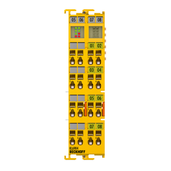
3.1 General description KL6904 TwinSAFE logic terminal with four fail-safe outputs The KL6904 is a safe small controller with digital outputs for connecting actuators (contactors, relays, etc.) with a maximum current 0.5 A (24 V ). The Bus Terminal has 4 fail-safe outputs. -
Page 13: Appropriate Use
TwinSAFE terminals may only be used for the purposes described below! WARNING The TwinSAFE terminals expand the application range of Beckhoff Bus Terminal system with functions that enable them to be used for machine safety applications. The TwinSAFE terminals are designed for machine safety functions and directly associated industrial automation tasks. -
Page 14: Technical Data
100 m Wire cross section min. 0.75 mm Input process image 192 byte max. Output process image 192 byte max. KL6904 supply voltage 24 V (-15%/+20%) Current consumption from K-bus maximum 250 mA Power dissipation of the terminal typically 2 W... -
Page 15: Dimensions
Product description 3.4 Dimensions Width: 24 mm (side-by-side installation) Height: 100 mm Depth: 68 mm KL6904... -
Page 16: Operation
4.1.2 Transport / storage Use the original packaging for transporting or storing the digital TwinSAFE terminals. Note the specified environmental conditions Please ensure that the digital TwinSAFE terminals are only transported and stored CAUTION under the specified environmental conditions (see technical data). KL6904... -
Page 17: Mechanical Installation
When correctly assembled, no significant gap should be visible between the housings. 3. During the installation of the Bus Terminals, the locking mechanism of the terminals must not come into conflict with the fixing bolts of the mounting rail. KL6904... -
Page 18: Electrical Installation
Bus Terminals must be taken account of, since some types (e.g. analog Bus Terminals or digital 4-channel Bus Terminals) do not or not fully loop through the power contacts. Power Feed Terminals (KL91xx, KL92xx) interrupt the power contacts and thus represent the start of a new supply rail. KL6904... - Page 19 Feed Terminal! In order to decouple further feed points for testing, these Power Feed Terminals can be released and pulled at least 10 mm from the group of terminals. Serious risk of injury! The PE power contact must not be used for other potentials! DANGER KL6904...
- Page 20 2. The wire can now be inserted into the round terminal opening without any force. 3. The terminal closes automatically when the pressure is released, holding the wire safely and permanently. Wire cross section 0.08 ... 2.5 mm Strip length 8 mm KL6904...
- Page 21 When selecting actuators please ensure that the KL2904 test pulses do not lead to Note actuator switching or diagnostic message from the KL2904. The test pulses of the KL6904 terminal outputs are not configurable and cannot be switched off. KL6904...
- Page 22 In each case one contactor N/C contact is connected in series to a TwinSAFE input of a KL1904. This TwinSAFE input is used as EDM signal (feedback loop) in the TwinSAFE logic configuration. Category 4 with two parallel-controlled contactors The N/O contacts of the contactors (not shown here) are connected in series and used for safety shutdown. KL6904...
- Page 23 Operation Category 4 with two contactors at two KL2904 outputs The N/O contacts of the contactors (not shown here) are connected in series and used for safety shutdown. KL6904...
-
Page 24: Tested Devices
The tests were carried out as function tests only. The information provided in the respective manufacturer documentation remains valid. Recommended protective circuits We recommend R/C or diode-based protective circuits for these devices. Note Varistor-based protective circuits should not be used. KL6904... -
Page 25: Configuration Of The Kl6904 In The Twincat System Manager
See TwinCAT automation software documentation. 4.2.4 Inserting a KL6904 A KL6904 is inserted in the same way as any other Beckhoff Bus Terminal. In the list open Safety Terminals (KLx9xx) and select the KL6904. The KL6904 can be selected with 7 or 15 TwinSAFE connections. - Page 26 KL6904 is delivered with 7 configured connections. The KL6904 can be configured with the KS2000 configuration software from Beckhoff (firmware version 14 or higher). After the changeover to the new process image the KL6904 must be de-energised and switched on again in order to activate the change.
-
Page 27: Address Settings On The Twinsafe Terminals
The TwinSAFE address of the terminal is set via the 10-way DIP switch on the left-hand side of the TwinSAFE Bus Terminal. TwinSAFE addresses between 1 and 1023 are available. DIP switch Address 1023 Unique TwinSAFE address Each TwinSAFE address may only be used once within a network! WARNING KL6904... -
Page 28: Entering The Twinsafe Addresses In The System Manager
Operation 4.2.6 Entering the TwinSAFE addresses in the System Manager The TwinSAFE address set at the DIP switch must also be entered under the TwinSAFE Logic tab (TwinSAFE address entry). KL6904... -
Page 29: Creating A Twinsafe Group
A TwinSAFE Group is a group of TwinSAFE terminals (inputs and outputs) that are logically linked via a KL6904. Any communication faults in the TwinSAFE connections of this group lead to the whole group being switched off. Other TwinSAFE Groups are not affected. - Page 30 All of the TwinSAFE group assigned function blocks are at a STOP state and thus all associated outputs are in a safe state. ERR Ack FB-Out All pending errors in the assigned function blocks and in the TwinSAFE connections are acknowledged by the FALSE->TRUE- Standard-In >FALSE signal sequence. KL6904...
- Page 31 All TwinSAFE connections of the TwinSAFE group have no errors OUT ERR TwinSAFE-Out TRUE: At least one locally assigned output of the TwinSAFE group has an error FB-In Standard-Out FALSE: All of the locally assigned outputs of the TwinSAFE group have no errors KL6904...
-
Page 32: Add A Function Block
Operation 4.2.8 Add a function block The KL6904 TwinSAFE logic terminal features the following blocks: emergency stop, machine monitoring, AND, OR, decoupler, operation mode, etc. A function block is added by right-clicking on the associated TwinSAFE function block list in the tree structure and selecting Append Function Block in the dialog box with the left mouse button (see diagram). - Page 33 Operation Appended emergency stop block KL6904...
- Page 34 The inputs are monitored for equality or inequality, depending on the contact type setting. A Discrepancy Time can be set for monitoring the two inputs for simultaneous switching. Make Contact: Contact type setting Break Contact Contact type setting The inputs are now activated. KL6904...
- Page 35 Operation The inputs can now be linked. Select the variable type: KL6904...
- Page 36 Operation Clicking on the New button opens the following dialog: All available channels are displayed as selected. The required channel is selected and highlighted in blue with the mouse. The selection is confirmed via the OK button. KL6904...
- Page 37 Operation The name of the variables should now be entered in the Link Alias field. Repeat the process for the other inputs. Inputs that are already in use are identified with an arrow. KL6904...
-
Page 38: Kl6904 User And Version Administration
The KL6904 has a user administration function. The administrator can create further users and issue associated passwords. Clicking on the Version History button will bring up the version history for the KL6904 (which cannot be deleted) that indicates who activated what version of a project on the KL6904, and when. -
Page 39: Loading The Project Into The Kl6904
The project is loaded into the KL6904 via the fieldbus. Use only qualified tools Only use a qualified tool for loading, verifying and enabling the project on the KL6904! CAUTION Click the Download button on the TwinSAFE Verifier tab for loading the project. - Page 40 The project is then displayed in text mode, and the user has to confirm consistency between the information displayed and the currently projected application by re-entering the password. The project is then started on the KL6904. 4.2.10.1 KL6904 project design limits TwinSAFE connections max.
-
Page 41: Communication Between Twincat Controllers
SLAVE_MESSAGE TwinSAFE Slave Subscriber MASTER_MESSAGE The link with the via TwinSAFE logic terminal KL6904 is established with the following dialog: The connection now has to be announced to the TwinSAFE logic terminal by selecting the TwinSAFE connection and right-clicking. The variables of type MASTER_MESSAGE and SLAVE_MESSAGE are now displayed, and both (In/Out) have to be selected. - Page 42 The F address of the partner device must also be set. Please not the DIP switch on the left-hand side of the KL6904. If several connections are to be established, a unique ID must be set for each Publisher variable.
- Page 43 Operation This ID must also be set on the partner device, i.e. the Subscriber. KL6904...
- Page 44 Operation The network variables can now be used in the project. The inputs are shown under TwinSAFE Input, the outputs under TwinSAFE Output. KL6904...
-
Page 45: Diagnostics
3 flash pulses Error in the function block and communication error: At least one connection is not in Run state. These errors can be rest through a falling edge at the ERR_ACK input of the TwinSAFE group. KL6904... - Page 46 Temperature difference error rapid flickering, alternating with 10 flash pulses error in output circuit through Open Load, external supply or cross-circuit These errors can only be reset by switching the power supply for the TwinSAFE terminal off and back on again. KL6904...
- Page 47 The Diag 3 and Diag 4 LEDs indicate internal terminal errors. Returning the terminal These errors lead to shutdown of the terminal. The terminal must be checked by Note Beckhoff Automation GmbH. Diag 3 LED (red) Diag 4 LED (red) Source of error flashing µC1...
-
Page 48: Maintenance
Housing components (polycarbonate, polyamide (PA6.6)) are suitable for plastic recycling. • Metal parts can be sent for metal recycling. • Electronic parts such as disk drives and circuit boards must be disposed of in accordance with national electronics scrap regulations. KL6904... -
Page 49: Appendix
Beckhoff products and system solutions. Beckhoff Support and Service is available to you wherever you are in the world, and can be reached by telephone, fax or e-mail. The contact addresses for your country may be found in the list of Beckhoff branches and partner firms. -
Page 50: Certificates
Appendix 5.3 Certificates KL6904... - Page 51 Appendix KL6904...
Need help?
Do you have a question about the KL6904 and is the answer not in the manual?
Questions and answers