Beckhoff TwinSAFE EL2904 Operating Instructions Manual
Terminal with 4 digital fail-safe outputs
Hide thumbs
Also See for TwinSAFE EL2904:
- Operating instructions manual (51 pages) ,
- Operating instructions manual (38 pages) ,
- Operating instructions manual (54 pages)

Related Manuals for Beckhoff TwinSAFE EL2904


Summary of Contents for Beckhoff TwinSAFE EL2904
- Page 1 Operating instructions | EN EL2904 TwinSAFE Terminal with 4 digital fail-safe outputs 2024-09-25 | Version: 3.3.0...
-
Page 3: Table Of Contents
Version numbers of the documentation .................... 7 Version history of the TwinSAFE product .................. 8 Staff qualification .......................... 9 Safety and instruction........................ 10 Beckhoff Support and Service...................... 11 Notes on information security...................... 12 2 For your safety ............................ 13 Duty of care ............................. 13 Safety image signs .......................... - Page 4 Table of contents Tested EL2904 devices........................ 39 7 Operation .............................. 40 Environmental conditions ........................ 40 Operation in potentially explosive atmospheres (ATEX) .............. 40 7.2.1 Special conditions ...................... 40 7.2.2 Identification ........................ 41 7.2.3 Date code and serial number ................... 42 7.2.4 Further ATEX documentation...................
-
Page 5: Notes On The Documentation
Notes on the documentation Disclaimer Beckhoff products are subject to continuous further development. We reserve the right to revise the operating instructions at any time and without prior announcement. No claims for the modification of products that have already been supplied may be made on the basis of the data, diagrams and descriptions in these operating instructions. -
Page 6: Limitation Of Liability
Modifications and changes to the hardware and/or software configuration that go beyond the documented options are prohibited and nullify the liability of Beckhoff Automation GmbH & Co. KG. The following is excluded from the liability: •... -
Page 7: Version Numbers Of The Documentation
Notes on the documentation Version numbers of the documentation Version Comment 3.3.0 • Editorially revised • Chapter renamed • Corrections • Chapters added 3.2.1 • Chapter "Due diligence" expanded • "Safety parameters" changed to "Target failure measures" • Corrections 3.2.0 •... -
Page 8: Version History Of The Twinsafe Product
Product features Only the product properties specified in the current operating instructions are valid. Further information given on the product pages of the Beckhoff homepage, in emails or in other publications is not authoritative. Version history of the TwinSAFE product This version history lists the software and hardware version numbers. -
Page 9: Staff Qualification
Notes on the documentation Staff qualification These operating instructions are intended exclusively for trained specialists in control technology and automation with the relevant knowledge. The trained specialist personnel must ensure that the applications and use of the described product meet all safety requirements. -
Page 10: Safety And Instruction
Notes on the documentation Safety and instruction Read the contents that refer to the activities you have to perform with the product. Always read the chapter For your safety [} 13] in the operating instructions. Observe the warnings in the chapters so that you can handle and work with the product as intended and safely. -
Page 11: Beckhoff Support And Service
The employees support you in the programming and commissioning of sophisticated automation systems. Hotline: +49 5246/963-157 E-mail: support@beckhoff.com Web: www.beckhoff.com/support Training Training in Germany takes place in our training center at the Beckhoff headquarters in Verl, at subsidiaries or, by arrangement, at the customer's premises. Hotline: +49 5246/963-5000 E-mail: training@beckhoff.com Web: www.beckhoff.com/training... -
Page 12: Notes On Information Security
Notes on the documentation Notes on information security The products of Beckhoff Automation GmbH & Co. KG (Beckhoff), insofar as they can be accessed online, are equipped with security functions that support the secure operation of plants, systems, machines and networks. -
Page 13: For Your Safety
• ISO 13849-1, Safety of machinery – Safety-related parts of control systems – Part 1: General principles for design Beckhoff is not responsible for the safe operation of the system. No disposal in domestic waste Products marked with a crossed-out waste bin must not be disposed of with domestic waste. -
Page 14: Safety Image Signs
For your safety Safety image signs Beckhoff products feature safety pictograms, either on stickers or printed, which vary depending on the product. They serve to protect people and to prevent damage to the products. Safety pictograms may not be removed and must be legible for the user. -
Page 15: General Safety Instructions
Engineering tools allowed are TE9000 - TwinCAT 3 Safety Editor and TE9200 - TwinSAFE Loader. Use only the latest versions of the engineering tools. You will find this on the Beckhoff website. Procedures or engineering tools that deviate from this are not covered by the certificate. This is especially true for externally generated xml files for the TwinSAFE import. -
Page 16: After Operation
For your safety 2.3.3 After operation De-energize and switch off components before working on them Check all safety-relevant equipment for functionality before working on the TwinSAFE component. Secure the working environment. Secure the machine or plant against being inadvertently started up. Observe the chapter Decommissioning [} 53]. -
Page 17: Product Overview
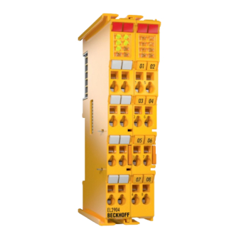
Product overview Product overview EL2904 – TwinSAFE terminal with 4 digital fail-safe outputs The EL2904 is a safe output terminal with digital outputs for connecting actuators (contactors, relays, etc.) with a maximum current 0.5 A (24 V ). The bus terminal has 4 fail-safe outputs. The EL2904 meets the requirements of IEC 61508:2010 SIL 3, EN ISO 13849-1:2023 (Cat 4, PL e), NRTL, UL508, UL1998 and UL991. -
Page 18: Block Diagram Of The El2904
This applies in particular to the use cases defined by Beckhoff Automation, which have been fully tested and certified and whose properties and operating conditions can be guaranteed. Use cases beyond this are regarded as inappropriate and require the approval of Beckhoff Automation. -
Page 19: Technical Data
Technical data Technical data Product data The current certificates of all TwinSAFE products with the underlying standards and directives can be found at https://www.beckhoff.com/en-en/support/download-finder/certificates-approvals/. Product designation EL2904 Number of outputs Status display 4 (one green LED per output) Fault reaction time ≤... - Page 20 Technical data Product designation EL2904 Inadmissible operating conditions TwinSAFE terminals must not be used under the following operating conditions: • under the influence of ionizing radiation (exceeding the natural background radiation) • in corrosive environments • in an environment that leads to unacceptable soiling of the bus terminal EMC immunity / emission conforms toEN 61000-6-2 / EN 61000-6-4...
-
Page 21: Target Failure Measures
Technical data CAUTION Compliance with the temperature limits The TwinSAFE component has a maximum internal temperature at which a switch-off takes place. This is designed for the maximum permissible ambient temperature. If the derating factor for the temperature for higher altitudes is used, the user is solely responsible for ensuring that the calculated maximum ambient temperature is complied with. -
Page 22: Dimensions
Technical data Dimensions Fig. 3: Dimensions of the EL2904 Width: 24 mm (side-by-side installation) Height: 100 mm Depth: 68 mm Lifetime TwinSAFE components have a lifetime of 20 years, during which the target failure measures are guaranteed. For more information, see the chapter Target failure measures. The lifetime starts from the date of manufacture according to the Date Code. -
Page 23: Fig. 4 Serial Number And Date Code
Technical data Legend: Example: Date Code 17 11 05 00 CW: calendar week of manufacture Calendar week: 17 YY: year of manufacture Year: 2011 SW: software version Software version: 05 HW: hardware version Hardware version: 00 In addition the TwinSAFE components bear a unique serial number. 00000000 17110500 Fig. 4: Serial number and Date Code... -
Page 24: Transport And Storage
The TwinSAFE components can be stored for shorter or longer periods. Observe the conditions specified in chapter Environmental conditions. Check the seal for damage Check the barcode sticker used to seal the outer packaging for damage. If the sticker is missing, opened or damaged, please contact Beckhoff Support and Service [} 11]. Version: 3.3.0 EL2904... -
Page 25: Installation
Installation Installation Safety instructions Before installing and commissioning the TwinSAFE components please read the safety instructions in the foreword of this documentation. Mechanical installation WARNING Only work in a de-energized state The bus terminal system is under tension. Bring the bus terminal system into a safe, de-energized state before starting installation, disassembly or wiring of the TwinSAFE component. -
Page 26: Installation Position
07 08 PE PE EL1904 BECKHOFF Fig. 6: Installation position • All figures in millimeters Mount the mounting rail horizontally for the prescribed installation position. The connection surfaces of the EL terminals or KL terminals must point to the front. This can be seen in the figure below. -
Page 27: Arrangement Instructions
EL1904 EL1904 EL1904 EL3102 EL1904 EL3102 EL1904 EL6900 EL1904 EL1104 EL9410 EL1904 EL1104 EL1904 EL2904 EL1904 EL1904 EL2008 EL1904 EL6900 BECKHOFF BECKHOFF BECKHOFF BECKHOFF BECKHOFF BECKHOFF BECKHOFF BECKHOFF BECKHOFF BECKHOFF BECKHOFF BECKHOFF BECKHOFF BECKHOFF BECKHOFF BECKHOFF BECKHOFF BECKHOFF BECKHOFF BECKHOFF... -
Page 28: Fig. 8 Thermally Bad Arrangement
EL1904 EL1904 EL1904 EL3102 EL1904 EL3102 EL1104 EL1904 EL1904 EL1104 EL9410 EL6900 EL1904 EL1904 EL2904 EL1904 EL1904 EL2008 EL1904 EL2008 BECKHOFF BECKHOFF BECKHOFF BECKHOFF BECKHOFF BECKHOFF BECKHOFF BECKHOFF BECKHOFF BECKHOFF BECKHOFF BECKHOFF BECKHOFF BECKHOFF BECKHOFF BECKHOFF BECKHOFF BECKHOFF BECKHOFF BECKHOFF... -
Page 29: Mounting
EL1104 EL1904 EL1904 EL1104 EL1904 EL3102 EL1904 EL3102 EL1904 EL4112 EL6900 EL9110 EL1904 EL2904 EL1904 EL9110 EL1904 EL2008 EL1904 EL2008 BECKHOFF BECKHOFF BECKHOFF BECKHOFF BECKHOFF BECKHOFF BECKHOFF BECKHOFF BECKHOFF BECKHOFF BECKHOFF BECKHOFF BECKHOFF BECKHOFF BECKHOFF BECKHOFF BECKHOFF BECKHOFF BECKHOFF BECKHOFF... - Page 30 Installation Ensure a functional component connection Observe the assembly sequence described. First connect adjacent TwinSAFE components together using tongue and groove. Only slide the TwinSAFE component onto the mounting rail after it has been plugged together. If the tongue and groove do not interlock, a functional connection will not be established. When correctly assembled, no significant gap should be visible between the housings.
-
Page 31: Electrical Installation
Installation 2. Push the TwinSAFE Terminal [3] together with the adjacent component with tongue and groove 3. Push the TwinSAFE Terminal [3] against the mounting rail [1] until the locking mechanism audibly engages on the mounting rail Electrical installation 6.3.1 Overvoltage protection Provide a surge filter against overvoltage for the supply voltage of the bus terminal block and the TwinSAFE components if protection against overvoltage is required in your system. -
Page 32: El2904 Pin Assignment
Installation 6.3.2 EL2904 pin assignment Fig. 10: EL2904 pin assignment Terminal point Output Signal not used, no function positive power contact negative power contact not used, no function not used, no function positive power contact negative power contact not used, no function 1’... -
Page 33: Connection
Installation 6.3.3 Connection Several conductors on one connection If you want to connect several conductors to one connection, connect the conductors in an upstream wiring, for example with terminal blocks. 6.3.3.1 Conductor with ferrule Solid and fine-stranded conductors with ferrules can be inserted directly into the terminal point without actuation. - Page 34 Installation 3. Insert the wire [3] into the round terminal opening 4. Pull the screwdriver [2] out of the opening The terminal [1] closes automatically when the pressure is released. The wire [3] is held securely and permanently. The permissible conductor cross-section can be found in the technical data.
-
Page 35: Connections
Installation 6.3.4 Connections The electrical connections between the TwinSAFE components are realized automatically by plugging the components together. 6.3.4.1 Spring contacts of the E-bus NOTICE Observe the E-bus current Observe the maximum current that your EtherCAT Coupler can supply to the E-bus. Use the EL9410 Power Supply Terminal if the current consumption of your TwinSAFE Terminals exceeds the maximum current that your EtherCAT coupler can supply for the E-bus supply. -
Page 36: Signal Lines
Installation Output side +5VDC supply voltage of the E-bus 0 VDC ground of the E-bus supply voltage Transmission line TX + Transmission line TX - Receive line RX + Receive line RX - 6.3.4.2 Power contacts Note the connection of the power contacts During the design of a bus terminal block, note the contact assignments of the individual TwinSAFE components, as some components do not loop through the power contacts or do not loop them through completely. - Page 37 Installation Common signal routing with other clocked signals in a common cable also reduces the maximum expansion. The reason for this is that the signals may crosstalk over long cable lengths and diagnostic messages may appear. The following figures show correct and incorrect signal routing. Please refer to the figure legend. Figure legend Distance between the cable channels Blue arrows...
-
Page 38: Twinsafe Reaction Times
Installation TwinSAFE reaction times The TwinSAFE terminals form a modular safety system that exchanges safety-oriented data via the Safety- over-EtherCAT protocol. This chapter is intended to help you determine the system's reaction time from the change of signal at the sensor to the reaction at the actuator. Typical response time The typical response time is the time required for transferring a piece of information from the sensor to the actuator, when the whole system operates normally, without error. -
Page 39: Tested El2904 Devices
Modifications of these products cannot be considered here. If you are unsure please test the hardware together with the TwinSAFE terminal. Manufacturer Type Comment Beckhoff AX5801 TwinSAFE Drive option card: safe restart lock Beckhoff AX2000 AS option... -
Page 40: Operation
80°C at the wire branching points, then cables must be selected whose temperature data correspond to the actual measured temperature values! Observe the permissible ambient temperature range of 0 to 55 °C when using Beckhoff fieldbus components in potentially explosive atmospheres! -
Page 41: Identification
• EN 60079-15: 2005 7.2.2 Identification Beckhoff fieldbus components that are certified for use in potentially explosive atmospheres bear one of the following markings: II 3 G Ex nA IIC T4 Gc KEMA 10ATEX0075 X Ta: 0 … 55 °C II 3 G Ex nA nC IIC T4 Gc KEMA 10ATEX0075 X Ta: 0 …... -
Page 42: Date Code And Serial Number
Inserting a Bus Terminal See TwinCAT automation software documentation. 7.3.3 Inserting an EL2904 An EL2904 is inserted in the same way as any other Beckhoff Bus Terminal. In the list open Safety Terminals (ELx9xx) and select the EL2904. Version: 3.3.0 EL2904... -
Page 43: Fig. 13 Inserting An El2904
Operation Fig. 13: Inserting an EL2904 EL2904 Version: 3.3.0... -
Page 44: Address Settings On Twinsafe Terminals With 1023 Possible Addresses
Operation 7.3.4 Address settings on TwinSAFE terminals with 1023 possible addresses Fig. 14: Address settings on TwinSAFE terminals with 1023 possible addresses The TwinSAFE address of the terminal is set via the 10-way DIP switch on the left-hand side of the TwinSAFE terminal. -
Page 45: Entering A Twinsafe Address And Parameters In The System Manager
Operation 7.3.5 Entering a TwinSAFE address and parameters in the System Manager The FSoE address set at the DIP switch must also be entered under the FSoE tab (FSoE Address entry). Fig. 15: Entering the FSoE address The EL2904 parameters are set under the respective TwinSAFE connection in the Connection and Parameter tabs. -
Page 46: Fig. 17 Setting The Parameters Of The Twinsafe Connection
Operation Fig. 17: Setting the parameters of the TwinSAFE connection Parameter overview PrmName Meaning Values Standard outputs In addition the output can be switched off from the standard PLC. The safe true / active output is linked with the standard logic signal AND. false Current Current measurement for the outputs is activated... -
Page 47: Diagnostics
Diag 3 (red) and Diag 4 (red) If the Diag 3 LED is lit, the Diag 4 LED indicates internal terminal errors. These errors lead to shutdown of the terminal. The terminal must be checked by Beckhoff Automation GmbH & Co. KG. -
Page 48: Diagnostic Objects
Diagnostics Flashing Code In the case of such an error, the Diag 4 LED on the EL2904 displays flashing codes that describe the error in more detail. A flashing code consists of four sequences, which are interrupted in each case by a short break. After the four sequences there is a long break, following which the flashing code is displayed again. -
Page 49: Possible Causes Of Diagnostic Messages
Diagnostics Index Name Meaning Flags Default : Overtemperature of the output board : Temperature too low µC1 : Temperature too low µC2 : Temperature of the output board too low : Temperature difference on the processor board too large : Temperature difference between the boards is too large *) These diagnostic messages are displayed only if Current Measurement active = false. - Page 50 Diagnostics Diagnostics Possible cause Remedial actions Diag 2 LED Terminal temperature too high Comply with the specified temperature range Flash code 8 EMC faults Take suitable EMC measures Internal defect Replace terminal Diag 2 LED Terminal temperature difference too large: Replace terminal Flash code 9 one of the 3 internal measuring points is faulty...
-
Page 51: Maintenance And Cleaning
Maintenance and cleaning Maintenance and cleaning Cleaning by the manufacturer only Do not operate the TwinSAFE component if it is unacceptably dirty. Refer to the technical data for the protection class. Send unacceptably dirty TwinSAFE component to the manufacturer for cleaning. TwinSAFE components are basically maintenance-free. - Page 52 Maintenance and cleaning 3. Pull the TwinSAFE component [1] out of the bus terminal block from the mounting rail [3] with little effort Version: 3.3.0 EL2904...
-
Page 53: 10 Decommissioning
In accordance with the WEEE-2012/19/EU directives, you can return used devices and accessories for professional disposal. The transport costs are borne by the sender. Send the used devices with the note "For disposal" to: Beckhoff Automation GmbH & Co. KG Gebäude „Service“ Stahlstraße 31... -
Page 54: 11 Appendix
Appendix 11 Appendix 11.1 Volatility If there are requirements concerning the volatility of products in your application, for example of the U.S. Department of Defense or similar authorities or security organizations, the following process applies: The product has both volatile and non-volatile components. Volatile components lose their data immediately after removing power. -
Page 55: Focus Of Certificates
The current certificates of all TwinSAFE components with the underlying standards and directives can be found at https://www.beckhoff.com/en-en/support/download-finder/certificates-approvals/. If the document refers only to the first four figures of a product (ELxxxx), the certificate is valid for all available variants of the component (ELxxxx-abcd). - Page 56 List of illustrations List of illustrations Fig. 1 EL2904 - TwinSAFE terminal with 4 digital fail-safe outputs............Fig. 2 Block diagram of the EL2904 ....................... Fig. 3 Dimensions of the EL2904 ......................Fig. 4 Serial number and Date Code...................... Fig. 5 Spring contacts ..........................
- Page 58 More Information: www.beckhoff.com/EL2904 Beckhoff Automation GmbH & Co. KG Hülshorstweg 20 33415 Verl Germany Phone: +49 5246 9630 info@beckhoff.com www.beckhoff.com...
Need help?
Do you have a question about the TwinSAFE EL2904 and is the answer not in the manual?
Questions and answers