
Subscribe to Our Youtube Channel
Related Manuals for Beckhoff EP3356-0022


Summary of Contents for Beckhoff EP3356-0022
- Page 1 Documentation for EP3356-0022 1-channel precise load cell analysis (resistor bridge), 24 bit Version: 1.1.0 Date: 2018-11-15...
-
Page 3: Table Of Contents
4.6.2 BG2000-0000 - EtherCAT Box protection enclosure............ 44 4.6.3 ATEX Documentation ...................... 45 5 EP3356-0022 - Signal connection ...................... 46 Analog voltage inputs M12 and meaning of the LEDs.............. 46 6 Commissioning/Configuration ....................... 48 TwinCAT configuration setup, manual..................... 48 Configuration setup: TwinCAT - online scan ................... 51 EtherCAT slave process data settings (PDO) ................. 58... - Page 4 Table of contents Calibration and adjustment ...................... 80 Notices on analog specifications ..................... 84 Voltage measurement ........................ 89 6.10 Distributed Clocks mode (EL3356-0010 and EP3356-0022 only) ........... 91 6.11 Process data............................ 92 6.12 Object description and parameterization .................. 100 6.13 Example program .......................... 113 6.14 Restoring the delivery state ...................... 118 7 Appendix .............................. 119...
-
Page 5: Foreword
The TwinCAT Technology is covered, including but not limited to the following patent applications and patents: EP0851348, US6167425 with corresponding applications or registrations in various other countries. ® EtherCAT is registered trademark and patented technology, licensed by Beckhoff Automation GmbH, Germany. Copyright © Beckhoff Automation GmbH & Co. KG, Germany. -
Page 6: Safety Instructions
All the components are supplied in particular hardware and software configurations appropriate for the application. Modifications to hardware or software configurations other than those described in the documentation are not permitted, and nullify the liability of Beckhoff Automation GmbH & Co. KG. Personnel qualification This description is only intended for trained specialists in control, automation and drive engineering who are familiar with the applicable national standards. -
Page 7: Documentation Issue Status
Changes 1.1.0 • Update Safety instructions • Update chapter Mounting and Cabling 1.0.4 • Technical Data updated • EP3356-0022 – Signal connection updated 1.0.3 • Basic function principles updated 1.0.2 • Nut torque for connectors updated 1.0.1 • Parallel connection of strain gauges updated 1.0.0... -
Page 8: Product Overview
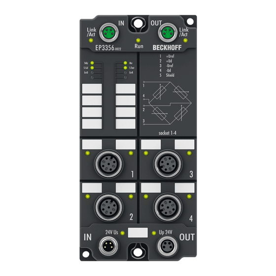
Product overview Product overview EP3356-0022 - Introduction Fig. 1: EP3356-0022 1-channel precise load cell analysis (resistor bridge), 24 bit The EP3356 EtherCAT Box enables direct connection of a resistor bridge or load cell in a 4-wire connection technology. The ratio between the bridge voltage U... -
Page 9: Ep3356-0022 - Technical Data
Product overview EP3356-0022 - Technical data Technical data EP3356-0022 Number of inputs 2, for 1 resistor bridge in full bridge technology Signal connection sockets [} 46] M12 Resolution 24 Bit, 32 bit presentation Conversion time 0.1 ms…250 ms, configurable, max. 10,000 samples/s Nominal voltage 24 V (-15 %/+20 %) -
Page 10: Basic Principles Of Strain Gauge Technology
(piezo-resistive effect); k-factors of up to 200 can be achieved. Measurement of signals The change in resistance of an individual strain gauge can be determined in principle by resistance measurement (current/voltage measurement) using a 2/3/4-conductor measurement technique Version: 1.1.0 EP3356-0022... -
Page 11: Fig. 3 Quarter, Half And Full Bridge
Measuring procedure The Beckhoff EL/KL335x Terminals and the EP3356 Box support only the constant excitation • Full bridge strain gauge at constant voltage (ratiometric measurement) Since the relative resistance change ΔR is low in relation to the nominal resistance R... -
Page 12: Fig. 4 4-Conductor Connection
In relation to a 350 Ω measuring bridge this means a measuring error of > 0.1 %. Fig. 4: 4-conductor connection This can be remedied by a 6-conductor connection, in particular for precision applications (only possible with EL3356). Fig. 5: 6-conductor connection Version: 1.1.0 EP3356-0022... -
Page 13: Fig. 6 Example Of A Load Cell
5 of the M12 connector. EP3356-0022: No 6-conductor connection necessary The connection of a strain gauge over 4-conductor with the EP3356-0022 is sufficient because due to the shorter cable lengths no measurement errors occur. - Page 14 Minimum application range or minimum measuring range in % of rated load This is the minimum measuring range/measuring range interval, which a calibratable load cell/set of scales must cover. Example: above load cell E = 10 kg; minimum application range e.g. 40 % E Version: 1.1.0 EP3356-0022...
-
Page 15: Fig. 7 Parallel Connection Of Strain Gauges
The mechanically parallel-connected load cells are usually also electrically connected in parallel and connect at two arbitrarily M12 sockets of EP3356-0022 (see figure below). To this end the following must be observed: •... - Page 16 • OIML (ORGANISATION INTERNATIONALE DE MÉTROLOGIE LÉGALE) www.oiml.org/en • PTB - Physikalisch-Technischen Bundesanstalt www.ptb.de/cms/ • www.eichamt.de • WELMEC - European cooperation in legal metrology www.welmec.org • DAkkS – Deutsche Akkreditierungsstelle www.dakks.de • Fachgemeinschaft Waagen (AWA) im Verband Deutscher Maschinen- und Anlagenbau VDMA www.vdma.org Version: 1.1.0 EP3356-0022...
-
Page 17: Basics Of Communication
The PDI watchdog can be used to monitor this communication for failure. The PDI watchdog monitors correct and timely process data communication with the ESC but from the application side. The SM and PDI watchdogs should be set separately for each slave in the TwinCAT System Manager: EP3356-0022 Version: 1.1.0... -
Page 18: Fig. 8 Ethercat Tab --> Advanced Settings --> Behavior --> Watchdog
1 to 65535, this covers a watchdog period of 0 to ~170 seconds. Calculation Multiplier = 2498 → watchdog base time = 1 / 25 MHz * (2498 + 2) = 0.0001 seconds = 100 µs SM watchdog = 10000 → 10000 * 100 µs = 1 second watchdog monitoring time Version: 1.1.0 EP3356-0022... - Page 19 OFF), depending on the SAFEOP and OP settings, and depending on the device and its settings. If this is prevented due to deactivation of watchdog monitoring in the module, outputs can be switched or remain set in device state SAFEOP. EP3356-0022 Version: 1.1.0...
-
Page 20: Ethercat State Machine
Before it acknowledges the change of state, the EtherCAT slave copies current input data into the associated DP- RAM areas of the EtherCAT slave controller (ECSC). Version: 1.1.0 EP3356-0022... - Page 21 In the Boot state the slave firmware can be updated. The Boot state can only be reached via the Init state. In the Boot state mailbox communication via the file access over EtherCAT (FoE) protocol is possible, but no other mailbox communication and no process data communication. EP3356-0022 Version: 1.1.0...
-
Page 22: Coe Interface
Not every EtherCAT device must have a CoE list. Simple I/O modules without dedicated processor usually have no variable parameters and therefore no CoE list. If a device has a CoE list, it is shown in the TwinCAT System Manager as a separate tab with a listing of the elements: Version: 1.1.0 EP3356-0022... -
Page 23: Fig. 10 Coe-Online Tab
Changes in the local CoE list of the terminal are lost if the terminal is replaced. If a terminal is re- placed with a new Beckhoff terminal, it will have the factory settings. It is therefore advisable to link all changes in the CoE list of an EtherCAT slave with the Startup list of the slave, which is pro- cessed whenever the EtherCAT fieldbus is started. -
Page 24: Fig. 11 Startup List In The Twincat System Manager
◦ the offline list from the ESI file is displayed. In this case modifications are not meaningful or possible. ◦ the configured status is shown under Identity ◦ no firmware or hardware version is displayed, since these are features of the physical device. ◦ Offline is shown in red Version: 1.1.0 EP3356-0022... -
Page 25: Fig. 12 Offline List
◦ the actual current slave directory is read. This may take several seconds, depending on the size and cycle time. ◦ the actual identity is displayed ◦ the firmware and hardware version of the equipment according to the electronic information is displayed. ◦ Online is shown in green Fig. 13: Online list EP3356-0022 Version: 1.1.0... -
Page 26: Distributed Clock
• … This is generally written as 0x80n0. Detailed information on the CoE interface can be found in the EtherCAT system documentation on the Beckhoff website. Distributed Clock The distributed clock represents a local clock in the EtherCAT slave controller (ESC) with the following characteristics: •... -
Page 27: Mounting And Cabling
Installation position variable Protection class IP65, IP66, IP67 (conforms to EN 60529) when screwed together Dimensions app. 126 x 30 x 26.5 mm app. 126 x 60 x 26,5 mm (H x W x D) app. 150 x 60 x 26.5 mm (without 7/8", B17) EP3356-0022 Version: 1.1.0... -
Page 28: Fixing
The mounting rail ZS5300-0011 (500 mm x 129 mm) has in addition to the M3 treads also pre-made M4 treads to fix 60 mm wide modules via their middle holes. Up to 14 narrow or 7 wide modules may be mixed mounted. Version: 1.1.0 EP3356-0022... -
Page 29: Nut Torque For Connectors
ZB8800 is also a max. torque of 0.5 Nm permissible. Fig. 16: EtherCAT Box with M8 connectors M12 connectors It is recommended to pull the M12 connectors tight with a nut torque of 0.6 Nm. Fig. 17: EtherCAT Box with M8 and M12 connectors EP3356-0022 Version: 1.1.0... -
Page 30: Additional Checks
Fig. 18: 7/8" plug connectors Torque socket wrenches Fig. 19: ZB8801 torque socket wrench Ensure the right torque Use the torque socket wrenches available by Beckhoff to pull the connectors tight (ZB8800, ZB8801-0000)! 4.1.4 Additional checks The boxes have undergone the following additional tests:... -
Page 31: Ethercat
• the Coupler Box (FBB-x110) has two M12 sockets Fig. 20: EtherCAT Box: M8, 30 mm housing Fig. 21: EtherCAT Box: M860 mm housing (example: EP9214) Fig. 22: Coupler Box: M12 Assignment There are various different standards for the assignment and colors of connectors and cables for Ethernet/ EtherCAT. EP3356-0022 Version: 1.1.0... -
Page 32: Ethercat - Fieldbus Leds
M8 connectors were changed to the colors of EN61918 (yellow, orange, white, blue).So different color coding exists. But the electrical properties are absolutely identical. EtherCAT connector The following connectors can be supplied for use in Beckhoff EtherCAT systems. Name Connector... - Page 33 Status of the EtherCAT module is operational EtherCAT statuses The various statuses in which an EtherCAT module may be found are described in the Basic Sys- tem Documentation for EtherCAT, which is available for download from our website (www.beck- hoff.com) under Downloads. EP3356-0022 Version: 1.1.0...
-
Page 34: Power Supply
Box Modules! This can damage the modules! Control voltage Us: 24 V Power is supplied to the fieldbus, the processor logic, the inputs and the sensors from the 24 V control voltage Us. The control voltage is electrically isolated from the fieldbus circuitry. Version: 1.1.0 EP3356-0022... - Page 35 Us and Up can thus easily be transferred from EtherCAT Box to EtherCAT Box. NOTE Pay attention to the maximum permissible current! Pay attention also for the redirection of the supply voltages Us and Up, the maximum permissible current for M8 connectors of 4 A must not be exceeded! EP3356-0022 Version: 1.1.0...
-
Page 36: Fig. 26 Ep92X4-0023, Connectors For Power In And Power Out
EP9214 or EP9224 (with integrated data logging, see www.beckhoff.com/EP9224) is recommended. With these modules intelligent power distribution concepts with up to 2 x 16 A and a maximum of 2.5 mm²... -
Page 37: Status Leds For Power Supply
Because of overload (current > 0.5 A) the sensor supply generated from power supply voltage Us was switched off for all sensors fed from this. Up (Auxiliary voltage) The power supply voltage Up is not present green illuminated The power supply voltage Up is present EP3356-0022 Version: 1.1.0... -
Page 38: Power Cable Conductor Losses M8
8 m power cable with 0.34 mm² cross-section has a voltage drop of 3.2 V at 4 A. EP92x4 Power Distribution Modules With EP9214 and EP9224 Power Distribution Modules intelligent concepts for voltage supply are available. Further information may be found under www.beckhoff.com/EP9224. Version: 1.1.0 EP3356-0022... -
Page 39: Conductor Losses 7/8
When wiring, note that with a rated voltage of 24 V the function of the modules can no longer be guaranteed from a voltage drop of 6 V. Variations in the output voltage from the power supply unit must also be taken into account. Fig. 30: ZK2030-xxxx-yyy - Conductor losses Alternatively, larger cable cross-section can be used, e.g. 2.5 mm EP3356-0022 Version: 1.1.0... -
Page 40: Cabling
Mounting and Cabling Cabling A list of EtherCAT cables, power cables, sensor cables, Ethernet/EtherCAT connectors and field- configurable connectors can be found under the following link: https://beckhoff.de/english/fieldbus_box/ ethercat_box_accessories_overview.htm?id=25525466903389 The corresponding data sheets can be found under the following link: https://beckhoff.de/english/ethercat-box/ethercat_box_cables.htm?id=690338951657421 EtherCAT cables Fig. 31: ZK1090-3131-0xxx... -
Page 41: Fig. 32 Zk2020-3132-0Xxx
Mounting and Cabling Power cable Fig. 32: ZK2020-3132-0xxx Sensor cables Fig. 33: Selection of Beckhoff sensor cables EP3356-0022 Version: 1.1.0... -
Page 42: Ul Requirements
To meet the UL requirements, EtherCAT Box Modules has to be operated only at an ambient temperature range of 0 to 55°C! Marking for UL All EtherCAT Box Modules certified by UL (Underwriters Laboratories) are marked with the following label. Fig. 34: UL label Version: 1.1.0 EP3356-0022... -
Page 43: Atex Notes
FF - firmware version HH - hardware version Beispiel mit Ser. Nr.: 29 10 02 01: 29 - week of production 29 10 - year of production 2010 02 - firmware version 02 01 - hardware version 01 EP3356-0022 Version: 1.1.0... -
Page 44: Bg2000-0000 - Ethercat Box Protection Enclosure
Put the cables for EtherCAT, power supply and sensors/actuators through the hole of the BG2000-0000 protection enclosure. Fig. 35: BG2000-0000, putting the cables Fix the wires for EtherCAT, power supply and sensors/actuators to the EtherCAT Box. Fig. 36: BG2000-0000, fixing the cables Version: 1.1.0 EP3356-0022... -
Page 45: Atex Documentation
Notes about operation of EtherCAT Box Modules (EPxxxx-xxxx) in potentially explo- sive areas (ATEX) Pay also attention to the continuative documentationNotes about operation of EtherCAT Box Mod- ules (EPxxxx-xxxx) in potentially explosive areas (ATEX) that is available in the download area of the Beckhoff homepage http:\\www.beckhoff.com! EP3356-0022 Version: 1.1.0... -
Page 46: Ep3356-0022 - Signal Connection
You can find an example for the parallel connection of strain gauges here [} 15]. The voltage U is 10 V and is supplied by the EP3356-0022. Do not earth the cable screen of the sensor on the sensor side If a shielded sensor cable is used, it should be not grounded on the sensor side. Otherwise it may come in certain system configurations to error of measurement. -
Page 47: Fig. 39 Leds Ep3356-0022
EP3356-0022 - Signal connection Meanings of the LEDs Fig. 39: LEDs EP3356-0022 Color Meaning green This LED indicates the terminals/boxes operating state: State of the EtherCAT State Machine [} 60]: INT = Initialization of the terminal/box blinking State of the EtherCAT State Machine: PREOP = Setting for... -
Page 48: Commissioning/Configuration
(default: C:\TwinCAT\IO\EtherCAT). The files are read (once) when a new System Man- ager window is opened. A TwinCAT installation includes the Beckhoff ESI files that were current at the time when the TwinCAT build was created. From TwinCAT 2.11 and in TwinCAT 3 the ESI di- rectory can be updated from the System Manager, if the programming PC is connected to the inter- net (TwinCAT →... -
Page 49: Fig. 40 Appending A New I/O Device (I/O Devices-> Right-Click -> Append Device
• Adding a new I/O device. In the following dialog select the device: EtherCAT (Direct Mode), and confirm with OK. Fig. 40: Appending a new I/O device (I/O Devices-> right-click -> Append Device...) Fig. 41: Selecting the device (EtherCAT) • Adding a new Box. EP3356-0022 Version: 1.1.0... -
Page 50: Fig. 42 Appending A New Box (Device -> Right-Click -> Append Box
Commissioning/Configuration Fig. 42: Appending a new box (Device -> right-click -> Append Box... ) • In the dialog that is displayed select the required Box (e.g. EP6224-2022) and confirm with OK. Fig. 43: Selecting a Box (e.g. EP6224-2022) Version: 1.1.0 EP3356-0022... -
Page 51: Configuration Setup: Twincat - Online Scan
(default: C:\TwinCAT\IO\EtherCAT). The files are read (once) when a new System Man- ager window is opened. A TwinCAT installation includes the Beckhoff ESI files that were current at the time when the TwinCAT build was created. From TwinCAT 2.11 and in TwinCAT 3 the ESI di- rectory can be updated from the System Manager, if the programming PC is connected to the inter- net (TwinCAT →... -
Page 52: Fig. 44 Twincat Config Mode Display
TwinCAT icon next to the Windows clock always shows the TwinCAT mode of the local IPC. The System Manager window shows the TwinCAT state of the target system. Right-clicking on "I/O Devices" in the configuration tree opens the search dialog. Version: 1.1.0 EP3356-0022... - Page 53 If the scan agent detects from the response that an EtherCAT device is connected, the port is immediately shown as an “EtherCAT Device”. Fig. 47: detected Ethernet devices After confirmation with “OK” a device scan is suggested for all selected devices (see the illustration below). EP3356-0022 Version: 1.1.0...
- Page 54 • “frames/sec” should match the cycle time taking into account the sent number of frames • no excessive “LostFrames” or CRC errors should occur The configuration is now complete. It can be modified as described under manual procedure. Version: 1.1.0 EP3356-0022...
- Page 55 If a scan is initiated for an existing configuration, the actual I/O environment may match the configuration exactly or it may differ. This enables the configuration to be compared. Fig. 51: Identical configuration If differences are detected, they are shown in the correction dialog, so that the user can modify the configuration as required. EP3356-0022 Version: 1.1.0...
- Page 56 If current ESI descriptions are available in the TwinCAT system, the last revision offered in the se- lection dialog matches the Beckhoff state of production. It is recommended to use the last device re- vision when creating a new configuration, if current Beckhoff devices are used in the real applica- tion.
- Page 57 Commissioning/Configuration Fig. 53: Example correction dialog with modifications Once all modifications have been saved or accepted, click “OK” to transfer them to the real *.tsm configuration. EP3356-0022 Version: 1.1.0...
-
Page 58: Ethercat Slave Process Data Settings (Pdo)
To this end the EtherCAT master (Beckhoff TwinCAT) parameterizes each EtherCAT slave during the start-up phase to define which process data (size in bits/bytes, source location, transmission type) it wants to transfer to or from this slave. -
Page 59: Configuration Via Twincat
(EP2816-0008 in this example). Fig. 55: Branch of the EtherCAT box to be configured In the right-hand window of the TwinCAT System manager, various tabs are now available for configuring the EtherCAT Box. General tab Fig. 56: General tab EP3356-0022 Version: 1.1.0... - Page 60 Indicates the configuration of the process data. The input and output data of the EtherCAT slave are represented as CANopen process data objects (PDO). The user can select a PDO via PDO assignment and modify the content of the individual PDO via this dialog, if the EtherCAT slave supports this function. Version: 1.1.0 EP3356-0022...
- Page 61 (not selected and greyed out), this indicates that the input is excluded from the PDO assignment. In order to be able do select a greyed out PDO, the currently selected PDO has to be deselected first. EP3356-0022 Version: 1.1.0...
- Page 62 (CoE) or Servo drive over EtherCAT protocol. This tab indicates which download requests are sent to the mailbox during startup. It is also possible to add new mailbox requests to the list display. The download requests are sent to the slave in the same order as they are shown in the list. Version: 1.1.0 EP3356-0022...
- Page 63 (CoE) protocol. This dialog lists the content of the object directory of the slave (SDO upload) and enables the user to modify the content of an object from this list. Details for the objects of the individual EtherCAT devices can be found in the device-specific object descriptions. EP3356-0022 Version: 1.1.0...
- Page 64 The Update list button updates all objects in the displayed list Auto Update If this check box is selected, the content of the objects is updated automatically. Advanced The Advanced button opens the Advanced Settings dialog. Here you can specify which objects are displayed in the list. Version: 1.1.0 EP3356-0022...
- Page 65 Offline If this option button is selected, the list of the objects included in the object - via EDS file directory is read from an EDS file provided by the user. Online tab Fig. 62: Online tab EP3356-0022 Version: 1.1.0...
- Page 66 A carrier signal is available at the port, but the port is closed. File Access over EtherCAT Download With this button a file can be written to the EtherCAT device. Upload With this button a file can be read from the EtherCAT device. Version: 1.1.0 EP3356-0022...
-
Page 67: Basic Function Principles
The measuring functions of the EL/EP3356 can be described as follows: • The EL3356 Analog Input Terminal and the EP3356-0022 Analog Input Box are used to acquire the supply voltage to a load cell as a reference voltage, and the differential voltage that is proportional to the force acting on the cell. - Page 68 ◦ Load cells approved and calibrated by the load cell manufacturer for parallel operation should be used. The nominal characteristic values [mV/V], zero offset [mV/V] and impedance [Ω, ohm] are then usually adjusted accordingly. ◦ a 6-wire connection is expressly recommended with the EL3356 Fig. 64: Parallel connection with EL3356 Version: 1.1.0 EP3356-0022...
- Page 69 • the minimum permissible assigned EtherCAT cycle time for the EL/EP3356 is 100 µs. • If the EL3356-0010/EP3356-0022 is to be used in Distributed Clocks mode: ◦ DC must be activated ◦ the Process data [} 92] Timestamp must be activated. The filter functionality is not available then.
- Page 70 • The filter with IIR characteristics is a discrete time, linear, time invariant filter that can be set to eight levels (level 1 = weak recursive filter, up to level 8 = strong recursive filter). The IIR can be understood to be a moving average value calculation after a low-pass filter. Version: 1.1.0 EP3356-0022...
- Page 71 Commissioning/Configuration Fig. 68: Step response and Bode diagramm of the IIR filter EP3356-0022 Version: 1.1.0...
- Page 72 Value PDO update PDO update Filter property Limit fre- Comment Rise time tings time EL3356 time quency (-3 dB) 10-90 % [s] (typ.) EP3356-0022/ [Hz] (typ.) EL3356-0010 Filter deacti- min. 10 ms Cycle-synchro- vated nous,, min. 100 µs FIR 50 Hz min. 10 ms 312.5 µs 50 Hz notch fil-...
- Page 73 ) ) * E (1.1) Calculation of the weight (1.2) Scaling factor (e.g. factor 1000 for rescaling from kg to g) * (G / 9.80665) (1.3) Influence of acceleration of gravity x Gain - Tara (1.4) Gain and Tare EP3356-0022 Version: 1.1.0...
- Page 74 The so–called conversion mode determines the speed and latency of the analog measurement in the EL/ EP3356. The characteristics: Mode Meaning typ. la- EL3356 EL3356-0010 typ. current tency consumption EP3356-0022 High precision 7,2 ms 70 % Analog conversion at 10.5 kSps (see Technical (samples per second) Slow conversion data [} 9] re-...
- Page 75 • activation of the averager • activation of the filter • type of filter Fig. 71: Setting parameters in CoE belonging to the individual modes The EL3356 has only mode 0, the El3356-0010 has modes 0 & 1. EP3356-0022 Version: 1.1.0...
- Page 76 If the sack is >90 % full, filling must be slowed down and the loading must be followed with higher accuracy; the filter must be closed. Therefore the two conversion modes can be switched via the process data bit "Sample mode" in the EL3356-0010 and in the EP3356-0022 in relation to the processing of the analog values.
-
Page 77: Application Notes
PLC, they are not components of the EL/EP3356. In the following example (recorded with Scope2) impulses on a 15 kg load cell are recorded; the filter is wide open at IIR1 so that steep edges occur in the signal. EP3356-0022 Version: 1.1.0... - Page 78 • scales of the accuracy class I to III are to be realized • scales that are generally independent of acceleration due to gravity are to be realized then one should check whether the gravity correction needs to be adapted via object 0x8000:26 [} 104]. Version: 1.1.0 EP3356-0022...
- Page 79 The Beckhoff EL/KL335x terminals and the EP3356 boxes cannot be officially calibrated as individual devices. However, they can be integrated as elements in applications that can then be equipped by the integrator with the required characteristics for official calibration capability using appropriate means.
-
Page 80: Calibration And Adjustment
EL/EP3356 and special versions Unless stated otherwise, the designation „EL/EP3356“ always refers also to special versions such as the EL3356-0010 and the EP3356-0022. Sensor calibration The EL/EP3356 is matched to the characteristic curve of the sensor element by means of the calibration. - Page 81 The calibration is of great importance for the accuracy of the system. In order to increase this, the filter should be set as strong as possible over the entire calibration phase. It may take several sec- onds before a static value is obtained. EP3356-0022 Version: 1.1.0...
- Page 82 This is necessary for the gross/net compensation of goods that cannot be weighed without a container that has a mass of its own. The EL/EP3356 supports 2 tarings; it is recommended to set a strong filter when taring. Temporary tare Version: 1.1.0 EP3356-0022...
- Page 83 The following commands can be transferred to the terminal/box via the CoE entry 0xFB00:01 [} 102]. Command Comment 0x0101 Execute zero balance 0x0102 Execute calibration 0x0001 Execute tare procedure (value is NOT saved in the terminal's/boxes EEprom) 0x0002 Execute tare procedure (value is saved in the terminal's/boxes EEprom) EP3356-0022 Version: 1.1.0...
-
Page 84: Notices On Analog Specifications
Analogous to pointing devices this is the measuring scale (see IEC 61131) or also the dynamic range. For analog I/O devices from Beckhoff the rule is that the limit with the largest value is chosen as the full scale value of the respective product (also called the reference value) and is given a positive sign. This applies to both symmetrical and asymmetrical measuring spans. - Page 85 In particular this also applies to SE, even though the term suggest that only one wire is required. • The term "electrical isolation" should be clarified in advance. Beckhoff IO modules feature 1…8 or more analog channels; with regard to the channel connection a distinction is made in terms of: ◦...
- Page 86 The property of electrical isolation indicates whether the channels are directly connected to each other. • Beckhoff terminals/boxes always feature electrical isolation between the field/analog side and the bus/ EtherCAT side. In other words, if two analog terminals/boxes are not connected via the power contacts, the modules are effectively electrically isolated.
- Page 87 One or two further sensor cables are used for the signal transmission of the current loop: 1. sensor cable: according to the Beckhoff terminology such sensors are to be connected to ‘single- ended’ inputs in 3 cables with +/-/Signal lines and if necessary FE/shield 2.
- Page 88 Commissioning/Configuration Fig. 79: 2/3/4-wire connection as single-ended or differential connection technology Version: 1.1.0 EP3356-0022...
-
Page 89: Voltage Measurement
EL/EP3356 and special versions Unless stated otherwise, the designation „EL/EP3356“ always refers also to special versions such as the EL3356-0010 and EP3356-0022. The EL/EP3356 principally offers a 2-channel voltage measurement on one terminal/box with 2 very different measuring ranges of ±25 mV and ±12 V nominal voltage. The load on the one connected strain gauge can be calculated from the two simultaneously measured voltages;... - Page 90 In the voltage measuring mode the EL3356 is to be connected to external GND with a single-ended connection. In addition the internal GND reference is to be closed by the CoE switch SymmetricRef- erencePotential. The EP3356 “supply” is not usable because the box internally generated 10 V. Version: 1.1.0 EP3356-0022...
-
Page 91: Distributed Clocks Mode (El3356-0010 And Ep3356-0022 Only)
Fig. 80: Activation of DC and PDO timestamp in the TwinCAT System Manager The EL3356-0010/EP3356-0022 operates free running with a cyclic, but not equidistant measurement; the time intervals between 2 measured values are therefore not constant. For this reason the 64-bit timestamp delivered with the process value must be evaluated by the user. -
Page 92: Process Data
The basic operating mode of the EL3356 terminal / EP3356 box is determined by the selection of the process data (PDO). EL/EP3356 and special versions EL/EP3356, EL3356-0010 and EP3356-0022 have the same process data except. EL3356: no mode switching in the ControlWord Selection of process data The process data of the EL/EP3356 are set up in the TwinCAT System Manager. - Page 93 In order to simplify the configuration, typical configuration combinations of process data are stored in the device description. The predefined configurations can be selected in the process data overview. Therefore the function is available only if the ESI/XML files are saved in the system (downloadable from the Beckhoff website).
- Page 94 • 2x AnalogIn (Compact): 2-channel voltage measurement, 32-bit integer voltage value only Default process image The default process image is standard (INT32). Fig. 82: Default process image, EL3356-0010 / EP3356-0022 Note regarding EL/EP3356: No switching of SampleMode in the Ctrl word Version: 1.1.0...
- Page 95 The format matches the REAL format of IEC 61131-3, which in turn is based on the REAL format of IEC 559. A REAL number (single precision) is defined as follows (See also Beckhoff InfoSys: TwinCAT PLC Control: standard data types). In accordance with IEC 61131 this 32-bit variable can be directly linked with a FLOAT variable of the PLC.
- Page 96 Fixed-point representation of the load The display of the load value can also be converted already in the terminal/box into a point representation. To do this the input PDOs are to be changed as follows: Fig. 83: Load value in fixed-point representation Version: 1.1.0 EP3356-0022...
- Page 97 The format matches the REAL format of IEC 61131-3, which in turn is based on the REAL format of IEC 559. A REAL number (single precision) is defined as follows (See also Beckhoff InfoSys: TwinCAT PLC Control: standard data types). This 32-bit variable can be linked directly with a FLOAT variable of the PLC according to IEC61131.
- Page 98 DcInputShift indicates by how many nanoseconds [ns] before or after the global Sync the terminal/box determines your process data. For further information on this, see the EtherCAT system description. Since the EL3356-0010/EP3356-0022 is not DC-triggered but determines the timestamp itself, these values have no meaning in the EL3356-0010/EP3356-0022. Version: 1.1.0...
- Page 99 PDOs 0x1600 (de- RMB Control (Resistor Measure- 0x7000:01 [} 103] - Start calibration fault) ment bridge) 0x7000:02 [} 103] - Disable calibration 0x7000:03 [} 103] - Input freeze 0x7000:04 [} 103] - Sample Mode (only EL3356-0010/EP3356-0022) 0x7000:05 [} 103] - Tara EP3356-0022 Version: 1.1.0...
-
Page 100: Object Description And Parameterization
EtherCAT XML Device Description The display matches that of the CoE objects from the EtherCAT XML Device Description. We rec- ommend downloading the latest XML file from the download area of the Beckhoff website and in- stalling it according to installation instructions. - Page 101 This interval is always a multiple (default: 10 ) of the calibration interval (0x8000:31So the delivery state of the testing interval result from 10 x 180 s = 1800 s. The self test can be prevented by setting the process data bit "Disable calibration" EP3356-0022 Version: 1.1.0...
- Page 102 - 0x0002 Tara setting (Data are saved into the EEPROM) see commands [} 67] FB00:02 Status State of the current executed command UINT8 0x00 (0 0: Command executed without errors 255: Execution of command FB00:03 Response Optional return value of the command OCTET- STRING[4] Version: 1.1.0 EP3356-0022...
- Page 103 6000:12 Value (Real) Measuring value as REAL REAL32 0x00000000 6000:13 Timestamp Timestamp of current measuring value (only UINT64 EL3356-0010/EP3356-0022 in DC-Mode) Input data Index 6010, 6020 AI Inputs Index (hex) Name Meaning Data type Flags Default 60n0:0 AI Inputs Max. subindex...
- Page 104 Meaning Data type Flags Default 1009:0 Hardware version Hardware version of the EtherCAT slave STRING Index 100A Software version Index (hex) Name Meaning Data type Flags Default 100A:0 Software version Firmware version of the EtherCAT slave STRING Version: 1.1.0 EP3356-0022...
- Page 105 0x06 (6 1800:06 Exclude TxPDOs This entry contains the TxPDOs (Index of the Tx- OCTET- 04 1A 05 1A 06 PDO Mapping objects) which shall not be trans- STRING[10] 1A 07 1A 00 00 mitted with TxPDO 1 EP3356-0022 Version: 1.1.0...
- Page 106 0x06 (6 1807:06 Exclude TxPDOs This entry contains the TxPDOs (Index of the Tx- OCTET- 06 1A 00 1A 01 PDO Mapping objects) which shall not be trans- STRING[10] 1A 02 1A 03 1A mitted with TxPDO 8 Version: 1.1.0 EP3356-0022...
- Page 107 Index 1A03 RMB TxPDO-Map Timestamp Index (hex) Name Meaning Data type Flags Default 1A03:0 RMB TxPDO-Map Timestamp PDO Mapping Value Timestamp UINT8 0x01 (1 1A03:01 SubIndex 001 1. PDO Mapping entry (object 0x0000, entry UINT64 0x0000:00, 64 0x00) EP3356-0022 Version: 1.1.0...
- Page 108 Sync-Manager Type Channel 2: Mailbox Read UINT8 0x02 (2 1C00:03 SubIndex 003 Sync-Manager Type Channel 3: Process Data UINT8 0x03 (3 Write (Outputs) 1C00:04 SubIndex 004 Sync-Manager Type Channel 4: Process Data UINT8 0x04 (4 Read (Inputs) Version: 1.1.0 EP3356-0022...
- Page 109 TxPDO Mapping object) (6656 1C13:02 Subindex 002 2. assigned TxPDO (contains the index of the UINT16 0x1A01 corresponding TxPDO Mapping object) (6657 1C13:03 Subindex 003 3. assigned TxPDO (contains the index of the UINT16 corresponding TxPDO Mapping object) EP3356-0022 Version: 1.1.0...
- Page 110 Number of the too short distances between UINT16 0x0000 (0 SYNC0 and SYNC1 Event (only in DC Mode) 1C32:20 Sync error TRUE: In the last cycle the synchronization was BOOLEAN 0x00 (0 not correct (only in DC-Mode) Version: 1.1.0 EP3356-0022...
- Page 111 Index spacing of the objects of the individual UINT16 0x0010 (16 channels F000:02 Maximum number of modules Number of channels UINT16 0x0001 (1 Index F008 Code word Index (hex) Name Meaning Data type Flags Default F008:0 Code word reserved UINT32 0x00000000 EP3356-0022 Version: 1.1.0...
- Page 112 Index F010 Module list Index (hex) Name Meaning Data type Flags Default F010:0 Module list Max. subindex UINT8 0x03 (3 F010:01 SubIndex 001 UINT32 0x00000172 (370 F010:02 SubIndex 002 AI UINT32 0x0000012C (300 F010:03 SubIndex 003 AI UINT32 0x0000012C (300 Version: 1.1.0 EP3356-0022...
-
Page 113: Example Program
In this example program an EP3356 is addressed by a PLC program (for TwinCAT 2). The Zip-file (https:// infosys.beckhoff.com/content/1033/ep3356/Resources/zip/1856737419.zip) contains the PLC*.pro and the System Manager*.tsm. The terminal can be operated via simple visualization; the function InputFreeze is programmed out by way of example. - Page 114 An EL9510 power supply terminal is used here to feed the strain gauge with 10 V. The EP3356 box is to be connected as shown below: Fig. 87: EP3356: Connection of the load sensor/full bridge The sensor power supply of 10 V is produced in EP3356. Version: 1.1.0 EP3356-0022...
- Page 115 (see the following two figures) Fig. 88: Searching the Ethernet adapter Fig. 89: Selection and confirmation of the Ethernet adapter • Activation of the configuration and confirmation (see the following two figures) Fig. 90: Activation of the configuration EP3356-0022 Version: 1.1.0...
- Page 116 • In TwinCAT PLC, under the "Project" menu, select "Rebuild all" to compile the project (see following figure) Fig. 94: Compile project In TwinCAT PLC: log in with the "F11" button, confirm loading the program (see following figure), run the program with the "F5" button Version: 1.1.0 EP3356-0022...
- Page 117 Commissioning/Configuration Fig. 95: Confirming program start EP3356-0022 Version: 1.1.0...
-
Page 118: Restoring The Delivery State
Fig. 97: Entering a restore value in the Set Value dialog Alternative restore value In some older terminals / boxes the backup objects can be switched with an alternative restore value: Decimal value: 1819238756 Hexadecimal value: 0x6C6F6164 An incorrect entry for the restore value has no effect. Version: 1.1.0 EP3356-0022... -
Page 119: Appendix
(ph-Value > 12) > 40°C: not resistant Acetic acid not resistant Argon (technical clean) resistant • resistant: Lifetime several months • non inherently resistant: Lifetime several weeks • not resistant: Lifetime several hours resp. early decomposition EP3356-0022 Version: 1.1.0... -
Page 120: Ethercat Box- / Ethercat P Box - Accessories
M12/wrench size 13, for torque wrench ZB8801-0000 ZB8801-0003 torque cable key, M12 field assembly/wrench size 13, for torque wrench ZB8801-0000 Further accessories Further accessories may be found at the price list for Beckhoff fieldbus components and at the inter- net under https://www.beckhoff.com Version: 1.1.0 EP3356-0022... -
Page 121: Support And Service
Beckhoff's branch offices and representatives Please contact your Beckhoff branch office or representative for local support and service on Beckhoff products! The addresses of Beckhoff's branch offices and representatives round the world can be found on her internet pages: http://www.beckhoff.com You will also find further documentation for Beckhoff components there. - Page 122 Fig. 30 ZK2030-xxxx-yyy - Conductor losses ..................Fig. 31 ZK1090-3131-0xxx ........................Fig. 32 ZK2020-3132-0xxx ........................Fig. 33 Selection of Beckhoff sensor cables.................... Fig. 34 UL label............................Fig. 35 BG2000-0000, putting the cables ....................Fig. 36 BG2000-0000, fixing the cables....................Fig. 37 BG2000-0000, mounting the protection enclosure ..............
- Page 123 Activation of DC and PDO timestamp in the TwinCAT System Manager........Fig. 81 EP3356 - process data selection in the TwinCAT System Manager ........... Fig. 82 Default process image, EL3356-0010 / EP3356-0022 ..............Fig. 83 Load value in fixed-point representation..................Fig. 84 Voltage measurement........................
- Page 124 Restarting TwinCAT in RUN mode ....................116 Fig. 94 Compile project..........................116 Fig. 95 Confirming program start ......................117 Fig. 96 Selecting the Restore default parameters PDO................118 Fig. 97 Entering a restore value in the Set Value dialog................118 Version: 1.1.0 EP3356-0022...
Need help?
Do you have a question about the EP3356-0022 and is the answer not in the manual?
Questions and answers