Beckhoff XTS Operating Instructions Manual
Starter kit with nct functionality
Hide thumbs
Also See for XTS:
- Startup manual (46 pages) ,
- Operating instructions manual (209 pages) ,
- Operating instructions manual (283 pages)

Related Manuals for Beckhoff XTS


Summary of Contents for Beckhoff XTS
- Page 1 Operating Instructions | EN XTS Starter Kit with NCT Functionality Linear product transport 2024-03-20 | Version 1.4...
-
Page 3: Table Of Contents
Connection strip 2 test board ....................26 Name plate............................27 3.5.1 DataMatrix code ........................28 Type key............................. 29 3.6.1 XTS starter kit with NCT functionality..................29 3.6.2 Motor module .......................... 29 3.6.3 Mover ............................30 Product characteristics........................31 Intended use ............................32 3.8.1... - Page 4 Adjust air gap .......................... 63 7.2.3 Disassembly ..........................64 7.2.4 Assembly ..........................66 Test board ............................67 7.3.1 Disassembly ..........................67 7.3.2 Assembly ..........................67 8 Decommissioning ............................69 Disassembly............................69 ─── XTS Starter Kit with NCT Functionality Version: 1.4...
- Page 5 Table of contents Disposal ............................. 70 8.2.1 Returning to the vendor......................70 9 Circuit diagram ............................71 Index ................................123 Version: 1.4 XTS Starter Kit with NCT Functionality ───...
-
Page 6: Documentation Notes
Documentation notes 1 Documentation notes 1.1 Disclaimer Beckhoff products are subject to continuous further development. We reserve the right to revise the documentation at any time and without notice. No claims for the modification of products that have already been supplied may be made on the basis of the data, dia- grams, and descriptions in this documentation. -
Page 7: Limitation Of Liability
• Use of untrained personnel • Use of unauthorized spare parts 1.1.4 Copyright © Beckhoff Automation GmbH & Co. KG, Germany The copying, distribution and utilization of this document as well as the communication of its contents to others without express autho- rization is prohibited. -
Page 8: Version Numbers
Product features The valid product features are always those specified in the current documentation. Further information given on the product pages of the Beckhoff homepage, in emails or in other publications is not au- thoritative. 1.3 Scope of the documentation... -
Page 9: Staff Qualification
Trained special- ists can: • apply relevant standards and directives • assess tasks that they have been assigned • recognize possible hazards • prepare and set up workplaces Version: 1.4 XTS Starter Kit with NCT Functionality ───... - Page 10 • independently recognize, avoid and eliminate sources of danger • implement specifications from the accident prevention regula- tions • assess the work environment • independently optimize and carry out their work ─── XTS Starter Kit with NCT Functionality Version: 1.4...
-
Page 11: Safety And Instruction
Examples This symbol shows examples of how to use the product or software. Required tool This symbol indicates a tool that is required for the following steps. Version: 1.4 XTS Starter Kit with NCT Functionality ───... - Page 12 QR codes This symbol shows a QR code that you can scan to watch videos or animations. Internet access is required in order to use it. ─── XTS Starter Kit with NCT Functionality Version: 1.4...
-
Page 13: Beckhoff Services
+49 5246 963-157 support@beckhoff.com www.beckhoff.com/en-en/support/our-support-services/ 1.7.2 Training offerings Training in Germany takes place at the Beckhoff branches or, after consultation, at the customer's premises. Beckhoff offers both face- to-face and online training courses. +49 5246 963-5000 training@beckhoff.com www.beckhoff.com/en-en/support/training-offerings/ 1.7.3 Service offerings... -
Page 14: Headquarters Germany
Hülshorstweg 20 33415 Verl, Germany +49 5246 963-0 info@beckhoff.com www.beckhoff.com/en-en/ A detailed overview of the Beckhoff locations worldwide can be found at: www.beckhoff.com/en-en/company/global-presence/ 1.7.5 Downloadfinder In the Download finder you will find configuration files, technical doc- umentation and application reports to download. -
Page 15: For Your Safety
Read the documentation prepared by the machine manufac- turer. 2.1.1 Before operation Danger from magnetic fields The magnetic fields of some of the components of the XTS are dan- gerous to: • people fitted with cardiac pacemakers • persons with magnetically conducting implants •... -
Page 16: During Operation
Ensure that the protective conductor is connected properly. Never disconnect electrical connections while they are live. Only work on the XTS when the voltage has dropped to < 10 V. Disconnect all components from the mains and secure against reconnection. -
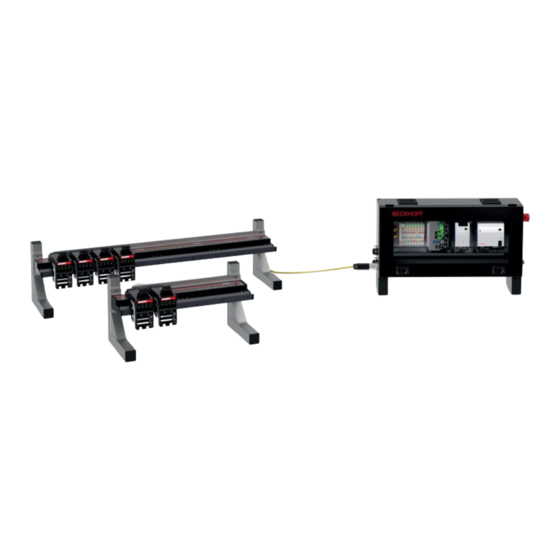
Page 17: Product Overview
Connector Straight motor module with integrated NCT functionality Basic electronics 2 x 9 connection strip basic electronics 2 x 9 connection strip test board Test board Mover Guide rail End cap Version: 1.4 XTS Starter Kit with NCT Functionality ───... -
Page 18: Control Cabinet Part 1
RJ45 connector for data line Cap for RJ45 connector RJ45 connector for additional I/Os Connector for connecting cable Cap for RJ45 connector Locking control cabinet door Window in control cabinet door ─── XTS Starter Kit with NCT Functionality Version: 1.4... -
Page 19: Control Cabinet Part 2
Product overview 3.2 Control cabinet part 2 Position Designation On/off switch Emergency stop button Start button Stop button Reset button Power supply Version: 1.4 XTS Starter Kit with NCT Functionality ───... -
Page 20: Nct Electronics
3.3 NCT electronics Position Designation 2 x 9 NCT electronics connection strip Fastening screw M6 x 25 Power LED Communication LED LED 1, test board in operation LED 2, application-specific. Not yet occupied. ─── XTS Starter Kit with NCT Functionality Version: 1.4... -
Page 21: X 9 Nct Electronics Connection Strip
Digital output 3 Digital output 2 Digital output 4 Not yet occupied. Not yet occupied. Not yet occupied. Not yet occupied. Ground 24 V PWM output 1 Ground PWM output 2 PWM output 3 Version: 1.4 XTS Starter Kit with NCT Functionality ───... -
Page 22: Test Board
Product overview 3.4 Test board 3 4 5 6 7 8 9 18 17 ─── XTS Starter Kit with NCT Functionality Version: 1.4... - Page 23 Switch 1: digital input 4 or analog input 2. Lower position: potentiometer on Potentiometer 2: 0 to 10 V potentiometer, analog input 2 Potentiometer 1: 0 to 10 V potentiometer, analog input 1 Connection strip 2 Connection strip 1 Button 1: digital input 1 LED button 1: button feedback 1 Version: 1.4 XTS Starter Kit with NCT Functionality ───...
-
Page 24: X 9 Connection Strip Test Board
Digital output 3 Digital output 2 Digital output 4 Not yet occupied. Not yet occupied. Not yet occupied. Not yet occupied. Ground 24 V PWM output 1 Ground PWM output 2 PWM output 3 ─── XTS Starter Kit with NCT Functionality Version: 1.4... -
Page 25: Connection Strip 1 Test Board
3.4.2 Connection strip 1 test board 10 11 12 Position Designation 24 V 24 V Ground Ground Digital output 1 Digital output 2 Digital output 3 Digital output 4 Ground PWM output 1 PWM output 2 PWM output 3 Version: 1.4 XTS Starter Kit with NCT Functionality ───... -
Page 26: Connection Strip 2 Test Board
13 14 15 16 17 18 19 20 21 22 23 24 Position Designation Potentiometer 2 Potentiometer 1 Digital input 1 Digital input 2 Digital input 3 Digital input 4 24 V Not yet occupied. Not yet occupied. 5 V Not yet occupied. Not yet occupied. ─── XTS Starter Kit with NCT Functionality Version: 1.4... -
Page 27: Name Plate
48 V | 16 A power supply status LED 24 V | 4 A power supply status LED Link / Act status LED Status LED ECAT Run Drive State status LED WEEE compliance EtherCAT marking Version: 1.4 XTS Starter Kit with NCT Functionality ───... -
Page 28: Datamatrix Code
3.5.1 DataMatrix code The DataMatrix code can be found on all movers and modules. If there is no Beckhoff Traceability Number (BTN) under the DataMa- trix code, you can read it out via the DataMatrix code. For example, you can read the DataMatrix code with the camera of your smartphone or tablet. -
Page 29: Type Key
Product overview 3.6 Type key 3.6.1 XTS starter kit with NCT functionality AT2100–001x Explanation Product area • AT = drive technology 2100 Product type • 2100 = starter kit System type • 001 = open end Product length • 1 = 500 mm •... -
Page 30: Mover
• 0 = standard • 1 = mover 1 Number of poles of the magnetic plate set • 5 = 5 poles Length of the magnetic plate set • 50 = 50 mm ─── XTS Starter Kit with NCT Functionality Version: 1.4... -
Page 31: Product Characteristics
Software-based control The XTS is controlled by a software-based cascade control. The control loop structure is stored in the XTS drivers and is calculated cyclically on the control IPC. No additional drive software is re- quired. Programming according to The standardized Motion Control function blocks according to the IEC 61131-3... -
Page 32: Intended Use
The components must be installed in electrical systems or machines and may only be put into operation as integrated components of the system or machine. All components of the XTS are intended only to be programmed and commissioned with the help of the Beckhoff TwinCAT automation software. -
Page 33: Technical Data
The synchronization accuracy depends on the mechanical rigidity, the applied load on the movers, the controller settings, the set velocity and also any mechanical offset between the modules. Version: 1.4 XTS Starter Kit with NCT Functionality ───... -
Page 34: Xts Starter Kits With Nct Functionality
Direct link to XTS NCT electronics, basic electronics Mover with NCT electronics fitted Direct link to the XTS mover with NCT electronics Direct link to the XTS mover with NCT electronics and Mover 1 functionality Motor module with integrated NCT functionality... -
Page 35: Dimensional Drawings
Technical data 4.3 Dimensional drawings Dimensional drawings and 3D models online You have the possibility to download the dimensional drawings and 3D models of the individual components from the Beckhoff website: www.beckhoff.com/de-de/support/downloadfinder 4.3.1 XTS starter kits All figures in millimeters AT2100-0011-0001 •... - Page 36 Technical data AT2100-0012-0001 • XTS starter kit with NCT functionality • 1000 mm • open end 1012 1000 ─── XTS Starter Kit with NCT Functionality Version: 1.4...
-
Page 37: Modules
Technical data 4.3.2 Modules All figures in millimeters AT2100-0250 • Straight • 250 mm • with integrated NCT functionality Version: 1.4 XTS Starter Kit with NCT Functionality ───... - Page 38 • with connector, direction of rotation to feedback system -0,1 250 -0,3 (51,7) (modular dimension 250) (51,2) M3 5 ~ 15 M3 5 8 (2x) 5 F6 (2x) Ø ± ± 55,1 90 0,2 ± 180 0,2 ± ± ─── XTS Starter Kit with NCT Functionality Version: 1.4...
-
Page 39: Nct Electronics
Technical data 4.3.3 NCT electronics All figures in millimeters AT8200-1000-0100 • NCT electronics, basic electronics • without mover Version: 1.4 XTS Starter Kit with NCT Functionality ───... - Page 40 Technical data AT8300-1100-0100 • NCT electronics, basic electronics mounted on mover AT9014-1070-0550 ─── XTS Starter Kit with NCT Functionality Version: 1.4...
- Page 41 Technical data AT8300-1200-0100 • NCT electronics, basic electronics mounted on mover AT9014-1070-1550 Version: 1.4 XTS Starter Kit with NCT Functionality ───...
-
Page 42: Mover
• Mover, 70 mm • 6 guide rollers, 2 of which are spring-loaded • with height adjustment for NCT electronics, basic electronics 76,3 ± 34,6 ± center of gravitiy weight: approx. 674g ± ± ─── XTS Starter Kit with NCT Functionality Version: 1.4... - Page 43 • Mover, 70 mm • 6 guide rollers, 2 of which are spring-loaded • with height adjustment for NCT electronics, basic electronics 76,3 ± 34,6 ± center of gravitiy weight: approx. 674g ± ± Version: 1.4 XTS Starter Kit with NCT Functionality ───...
-
Page 44: Commissioning
Commissioning 5 Commissioning After unpacking the XTS starter kit with NCT technology, you must remove the transport securing devices on the movers and connect the cables. 5.1 Preparation Required tool • Suitable torque wrench • Allen key 2 mm • Allen key 3 mm •... -
Page 45: Connect The Connection Cable
The connector of the module may be rotated by 90° a maximum of ten times. ► Plug the connector [1] of the connection cable to the connec- tor [2] of the module ► Tighten the connector [1] with assembly tool [+] Version: 1.4 XTS Starter Kit with NCT Functionality ───... -
Page 46: Control Cabinet
Commissioning 5.3.2 Control cabinet ► Remove cap [1] ► Plug the connector [1] of the connection cable into the connec- tor [2] of the control cabinet ► Tighten the connector [1] with assembly tool [+] ─── XTS Starter Kit with NCT Functionality Version: 1.4... -
Page 47: Connect Data Line
► Connect the connector [1] of the data line to the connector [2] in the control cabinet 5.4.2 PC or laptop ► Plug the connector [1] of the data line into the corresponding port of your PC [2] or laptop [3] Version: 1.4 XTS Starter Kit with NCT Functionality ───... -
Page 48: System Test
After the starter kit has been connected and switched on: The Stop button [1] on the control cabinet lights up red continuously. The Reset button [2] must flash blue. ► Press Reset button [1] ► Ensure that the Emergency stop button is unlocked ─── XTS Starter Kit with NCT Functionality Version: 1.4... - Page 49 ► Press the Start button [1] The Stop button [1] on the control cabinet must flash red. The Start button [2] on the control cabinet must light up green con- tinuously. The system is in operation. Version: 1.4 XTS Starter Kit with NCT Functionality ───...
-
Page 50: Stop System
The Stop button [1] must light up red continuously. The Reset button [2] must flash blue. 5.7.2 Emergency stop button ► Press the Emergency stop button [1] The Stop button [1] must light up red continuously. ─── XTS Starter Kit with NCT Functionality Version: 1.4... - Page 51 If the system is stopped with the Emergency stop button, the Emer- gency stop button must be unlocked to restart the system. ► Unlock the Emergency stop button [1] The Stop button [1] must light up red continuously. The Reset button [2] must flash blue. Version: 1.4 XTS Starter Kit with NCT Functionality ───...
-
Page 52: Functionality Of The Test Board
• Digital input 3 enabled: button 3 [3] with function • Analog input 1 disabled: potentiometer 1 [5] without function Switch [2] down • Digital input 3 disabled: button 3 [3] without function • Analog input 1 enabled: potentiometer 1 [5] with function ─── XTS Starter Kit with NCT Functionality Version: 1.4... -
Page 53: Push Button
LED. 6.2.1 Button 1 - digital input 1 ► Press button 1 [1] The LED 1 Digital output 1 [1] lights up. 6.2.2 Button 2 - digital input 2 ► Press button 2 [1] Version: 1.4 XTS Starter Kit with NCT Functionality ───... -
Page 54: Button 3 - Digital Input 3
► Make sure that the switch [2] is in the upper position The LED 3 Digital output 3 [1] lights up. 6.2.4 Button 4 - digital input 4 ► Press button 4 [1] ► Make sure that the switch [2] is in the upper position ─── XTS Starter Kit with NCT Functionality Version: 1.4... -
Page 55: Button 1 To 4
► Make sure that the switches [5] and [6] are in the upper position LEDs [1] to [4] are in chaser mode. 6.2.5.1 Exit chaser mode ► Keep keys [1] to [4] pressed for five seconds ► Make sure that the switches [5] and [6] are in the upper position Version: 1.4 XTS Starter Kit with NCT Functionality ───... - Page 56 Functionality of the test board LEDs [1] to [4] are off. ─── XTS Starter Kit with NCT Functionality Version: 1.4...
-
Page 57: Potentiometer
► Turn potentiometer 1 [1] to set the color of the RGB LED ► Make sure that the switch [2] is in the lower position The RGB LED [1] lights up in the set color. Version: 1.4 XTS Starter Kit with NCT Functionality ───... -
Page 58: Potentiometer 2 - Analog Input 2
► Turn potentiometer 2 [1] to adjust the brightness of the RGB LED ► Make sure that the switch [2] is in the lower position The RGB LED [1] lights up in the set brightness. ─── XTS Starter Kit with NCT Functionality Version: 1.4... -
Page 59: Assembly And Disassembly
The pre-assembled movers can be removed and inserted. Example XTS starter kit with open end The removal and insertion of the movers is exemplified by an XTS starter kit with open end. The rail on support [+] ZK9001-0000 is available for removing and inserting the movers on a circulating system. -
Page 60: Removing
► Insert and tighten the screws [2] ► Observe tightening torques: Components Tightening torque [Nm] Screw, M5 x 12 Screws, M3 x 14 7.1.2 Removing ► Remove the mover [1] via the rail on support [2] ─── XTS Starter Kit with NCT Functionality Version: 1.4... -
Page 61: Inserting
► Insert mover [1] with the NCT electronics [2] via the rail on sup- port [3] ► Observe correct alignment of the NCT electronics [2] to the name plate [4] Version: 1.4 XTS Starter Kit with NCT Functionality ───... -
Page 62: Nct Electronics
► Insert the feeler gauge blade [1] into the air gap [2] between the NCT electronics and the module The air gap must be adjusted if the feeler gauge blade cannot be in- serted into the air gap. ─── XTS Starter Kit with NCT Functionality Version: 1.4... -
Page 63: Adjust Air Gap
If the air gap is not yet set correctly: ► Loosen and tighten the set screws again ► Increasing the air gap Further information can be found in chapter "Increasing the air gap", [Page 64]. Version: 1.4 XTS Starter Kit with NCT Functionality ───... -
Page 64: Disassembly
Further information can be found in chapter "Reduce air gap", [Page 63]. 7.2.3 Disassembly ► Loosen screws [1] on the connector of the cable bridge ► Pull off the connector [2] of the cable bridge from the NCT elec- tronics [3] ─── XTS Starter Kit with NCT Functionality Version: 1.4... - Page 65 Assembly and disassembly ► Remove screws [1] ► Lift and remove the NCT electronics [2] in the area of the con- nector Version: 1.4 XTS Starter Kit with NCT Functionality ───...
-
Page 66: Assembly
Components Tightening torque [Nm] Screws, M6 x 25 ► Plug the connector [1] of the cable bridge into the connection strip of the NCT electronics [2] ► Tighten screws [3] on the cable bridge ─── XTS Starter Kit with NCT Functionality Version: 1.4... -
Page 67: Test Board
All other movers are not suitable for mounting the NCT electronics. ► Screw the test board [1] to the mover [3] with screws [2] ► Observe tightening torques: Components Tightening torque [Nm] Screws, M6 x 20 Version: 1.4 XTS Starter Kit with NCT Functionality ───... - Page 68 Assembly and disassembly ► Plug the connector [1] of the cable bridge into the connection strip of the test board [2] ► Tighten screws [3] on the cable bridge ─── XTS Starter Kit with NCT Functionality Version: 1.4...
-
Page 69: Decommissioning
► Remove cables and electrical connections ► Loosen the fixing screws of the guide rails and the modules ► Remove the modules from the machine one after the other ► Transport the XTS components to the workplace or put them into storage Version: 1.4 XTS Starter Kit with NCT Functionality ───... -
Page 70: Disposal
In addition, you have the option to contact a local certified specialist company for the disposal of used electrical and electronic appli- ances. Dispose of the old components in accordance with the regu- lations applicable in your country. ─── XTS Starter Kit with NCT Functionality Version: 1.4... -
Page 71: Circuit Diagram
Circuit diagram 9 Circuit diagram Version: 1.4 XTS Starter Kit with NCT Functionality ───... - Page 72 Circuit diagram ─── XTS Starter Kit with NCT Functionality Version: 1.4...
- Page 73 Circuit diagram Version: 1.4 XTS Starter Kit with NCT Functionality ───...
- Page 74 Circuit diagram ─── XTS Starter Kit with NCT Functionality Version: 1.4...
- Page 75 Circuit diagram Version: 1.4 XTS Starter Kit with NCT Functionality ───...
- Page 76 Circuit diagram ─── XTS Starter Kit with NCT Functionality Version: 1.4...
- Page 77 Circuit diagram Version: 1.4 XTS Starter Kit with NCT Functionality ───...
- Page 78 Circuit diagram ─── XTS Starter Kit with NCT Functionality Version: 1.4...
- Page 79 Circuit diagram Version: 1.4 XTS Starter Kit with NCT Functionality ───...
- Page 80 Circuit diagram ─── XTS Starter Kit with NCT Functionality Version: 1.4...
- Page 81 Circuit diagram Version: 1.4 XTS Starter Kit with NCT Functionality ───...
- Page 82 Circuit diagram ─── XTS Starter Kit with NCT Functionality Version: 1.4...
- Page 83 Circuit diagram Version: 1.4 XTS Starter Kit with NCT Functionality ───...
- Page 84 Circuit diagram ─── XTS Starter Kit with NCT Functionality Version: 1.4...
- Page 85 Circuit diagram Version: 1.4 XTS Starter Kit with NCT Functionality ───...
- Page 86 Circuit diagram ─── XTS Starter Kit with NCT Functionality Version: 1.4...
- Page 87 Circuit diagram Version: 1.4 XTS Starter Kit with NCT Functionality ───...
- Page 88 Circuit diagram ─── XTS Starter Kit with NCT Functionality Version: 1.4...
- Page 89 Circuit diagram Version: 1.4 XTS Starter Kit with NCT Functionality ───...
- Page 90 Circuit diagram ─── XTS Starter Kit with NCT Functionality Version: 1.4...
- Page 91 Circuit diagram Version: 1.4 XTS Starter Kit with NCT Functionality ───...
- Page 92 Circuit diagram ─── XTS Starter Kit with NCT Functionality Version: 1.4...
- Page 93 Circuit diagram Version: 1.4 XTS Starter Kit with NCT Functionality ───...
- Page 94 Circuit diagram ─── XTS Starter Kit with NCT Functionality Version: 1.4...
- Page 95 Circuit diagram Version: 1.4 XTS Starter Kit with NCT Functionality ───...
- Page 96 Circuit diagram ─── XTS Starter Kit with NCT Functionality Version: 1.4...
- Page 97 Circuit diagram Version: 1.4 XTS Starter Kit with NCT Functionality ───...
- Page 98 Circuit diagram ─── XTS Starter Kit with NCT Functionality Version: 1.4...
- Page 99 Circuit diagram Version: 1.4 XTS Starter Kit with NCT Functionality ───...
- Page 100 Circuit diagram ─── XTS Starter Kit with NCT Functionality Version: 1.4...
- Page 101 Circuit diagram Version: 1.4 XTS Starter Kit with NCT Functionality ───...
- Page 102 Circuit diagram ─── XTS Starter Kit with NCT Functionality Version: 1.4...
- Page 103 Circuit diagram Version: 1.4 XTS Starter Kit with NCT Functionality ───...
- Page 104 Circuit diagram ─── XTS Starter Kit with NCT Functionality Version: 1.4...
- Page 105 Circuit diagram Version: 1.4 XTS Starter Kit with NCT Functionality ───...
- Page 106 Circuit diagram ─── XTS Starter Kit with NCT Functionality Version: 1.4...
- Page 107 Circuit diagram Version: 1.4 XTS Starter Kit with NCT Functionality ───...
- Page 108 Circuit diagram ─── XTS Starter Kit with NCT Functionality Version: 1.4...
- Page 109 Circuit diagram Version: 1.4 XTS Starter Kit with NCT Functionality ───...
- Page 110 Circuit diagram ─── XTS Starter Kit with NCT Functionality Version: 1.4...
- Page 111 Circuit diagram Version: 1.4 XTS Starter Kit with NCT Functionality ───...
- Page 112 Circuit diagram ─── XTS Starter Kit with NCT Functionality Version: 1.4...
- Page 113 Circuit diagram Version: 1.4 XTS Starter Kit with NCT Functionality ───...
- Page 114 Circuit diagram ─── XTS Starter Kit with NCT Functionality Version: 1.4...
- Page 115 Circuit diagram Version: 1.4 XTS Starter Kit with NCT Functionality ───...
- Page 116 Circuit diagram ─── XTS Starter Kit with NCT Functionality Version: 1.4...
- Page 117 Circuit diagram Version: 1.4 XTS Starter Kit with NCT Functionality ───...
- Page 118 Circuit diagram ─── XTS Starter Kit with NCT Functionality Version: 1.4...
- Page 119 Circuit diagram Version: 1.4 XTS Starter Kit with NCT Functionality ───...
- Page 120 Circuit diagram ─── XTS Starter Kit with NCT Functionality Version: 1.4...
- Page 121 Circuit diagram Version: 1.4 XTS Starter Kit with NCT Functionality ───...
- Page 122 Circuit diagram ─── XTS Starter Kit with NCT Functionality Version: 1.4...
-
Page 123: Index
Tightening torques 16 Signal words 11 Starter kit LEDs 48 Product overview 17 Support 13 Symbols 11 System Module with connector Starting 48 Turns 45 Stop 50 Mover 59 System test 48 Version: 1.4 XTS Starter Kit with NCT Functionality ───... - Page 124 Index Target group 9 Test board Disassembly 67 Installation 67 Product overview 22 Transport securing device 44 Turns 45 Type key 29 ─── XTS Starter Kit with NCT Functionality Version: 1.4...
- Page 126 More Information: www.beckhoff.com/en-en/products/motion/xts-linear-product- transport/ Beckhoff Automation GmbH & Co. KG Hülshorstweg 20 33415 Verl Germany Phone: +49 5246 9630 info@beckhoff.com www.beckhoff.com...
Need help?
Do you have a question about the XTS and is the answer not in the manual?
Questions and answers