Beckhoff EL2904 Operating Instructions Manual
Twinsafe output terminal with 4 fail-safe outputs
Hide thumbs
Also See for EL2904:
- Operating instructions manual (51 pages) ,
- Operating instructions manual (54 pages) ,
- Operating instructions manual (58 pages)

Related Manuals for Beckhoff EL2904


Summary of Contents for Beckhoff EL2904
- Page 1 Operating instructions for EL2904 TwinSAFE output terminal with 4 fail-safe outputs Version: 1.2.0 Date: 2012-03-06...
-
Page 3: Table Of Contents
TwinSAFE 2.2.1 The I/O construction kit is extended safely 2.2.2 Safety concept 2.2.3 EL1904, EL2904 – Bus Terminals with 4 fail-safe inputs or outputs 2.2.4 EL6900 - TwinSAFE logic terminal 2.2.5 The fail-safe principle (Fail Stop) 3 Product description General description... - Page 4 Special conditions 4.2.2 Identification 4.2.3 Date code and serial number 4.2.4 Further ATEX documentation Configuration of the EL2904 in the TwinCAT System Manager 4.3.1 Inserting a Beckhoff Bus Coupler 4.3.2 Inserting a Beckhoff Bus Terminal 4.3.3 Inserting an EL2904 4.3.4 Address settings on the TwinSAFE terminals 4.3.5...
-
Page 5: Foreword
Offenders will be held liable for the payment of damages. All rights reserved in the event of the grant of a patent, utility model or design. 1.1.5 Delivery conditions In addition, the general delivery conditions of the company Beckhoff Automation GmbH apply. EL2904... -
Page 6: Safety Instructions
All the components are supplied in particular hardware and software configurations appropriate for the application. Modifications to hardware or software configurations other than those described in the documentation are not permitted, and nullify the liability of Beckhoff Automation GmbH. 1.2.2 Operator's obligation to exercise diligence The operator must ensure that ... -
Page 7: Description Of Safety Symbols
Damage to the environment or devices Failure to follow the instructions associated with this symbol can lead to damage to the Warning environment or equipment. Tip or pointer This symbol indicates information that contributes to better understanding. Note EL2904... -
Page 8: System Description
2 System description 2.1 The Beckhoff Bus Terminal system The Beckhoff Bus Terminal system is used for decentralized connection of sensors and actuators to a control system. The Beckhoff Bus Terminal system components are mainly used in industrial automation and building management applications. In its minimum configuration, a bus station consists of a Bus Coupler or a Bus Terminal Controller and Bus Terminals connected to it. -
Page 9: Bus Coupler
Connection technology Bus Coupler ® Wiring Cage Clamp spring-loaded system Connection cross-section 0.08 mm²... 2.5 mm , stranded wire, solid wire Fieldbus connection depending on fieldbus Power contacts 3 spring contacts Current load 10 A Rated voltage 24 V EL2904... -
Page 10: Bus Terminals
The operating voltage is passed on to following terminals via three power contacts. Terminal strip can be split into galvanically isolated groups by means of potential feed terminals as required. The power feed terminals play no part in the control of the terminals, and can be inserted at any locations within the terminal strip. EL2904... -
Page 11: Twinsafe
2.2.1 The I/O construction kit is extended safely With the TwinSAFE Terminals, Beckhoff offers the option of simply expanding the proven Bus Terminal system, and to transfer the complete cabling for the safety circuit into the already existing fieldbus cable. -
Page 12: El1904, El2904 - Bus Terminals With 4 Fail-Safe Inputs Or Outputs
2.2.3 EL1904, EL2904 – Bus Terminals with 4 fail-safe inputs or outputs The EL1904 and EL2904 Bus Terminals enable connection of common safety sensors and actuators. They are operated with the EL6900 TwinSAFE logic terminal. The TwinSAFE logic terminal is the link unit between the TwinSAFE input and output terminals. -
Page 13: Product Description
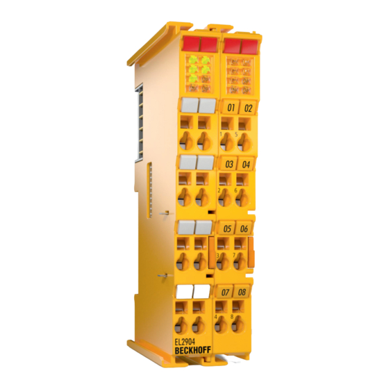
3.1 General description EL2904 - Digital four-channel TwinSAFE output terminal The EL2904 is a safe output terminal with digital outputs for connecting actuators (contactors, relays, etc.) with a maximum current 0.5 A (24 V ). The Bus Terminal has 4 fail-safe outputs. -
Page 14: Appropriate Use
TwinSAFE terminals may only be used for the purposes described below! WARNING The TwinSAFE terminals expand the application range of Beckhoff Bus Terminal system with functions that enable them to be used for machine safety applications. The TwinSAFE terminals are designed for machine safety functions and directly associated industrial automation tasks. -
Page 15: Technical Data
Output current per channel max. 500 mA, min. 20 mA with current measurement active Actuators When selecting actuators please ensure that the EL2904 test pulses do not lead to actuator switching. Cable length between (unshielded) max. 100 m actuator and terminal (shielded) max. -
Page 16: Dimensions
Product description 3.4 Dimensions Width: 24 mm (side-by-side installation) Height: 100 mm Depth: 68 mm EL2904... -
Page 17: Operation
4.1.2 Transport / storage Use the original packaging for transporting or storing the digital TwinSAFE terminals. Note the specified environmental conditions Please ensure that the digital TwinSAFE terminals are only transported and stored CAUTION under the specified environmental conditions (see technical data). EL2904... -
Page 18: Mechanical Installation
The direction indication “down” corresponds to the direction of positive acceleration due to gravity. In order to ensure optimum convection cooling, the distances to neighbouring devices and to control cabinet walls must not be smaller than those shown in the diagram. EL2904... - Page 19 When correctly assembled, no significant gap should be visible between the housings. 3. During the installation of the Bus Terminals, the locking mechanism of the terminals must not come into conflict with the fixing bolts of the mounting rail. EL2904...
-
Page 20: Electrical Installation
Bus Terminals must be taken account of, since some types (e.g. analog Bus Terminals or digital 4-channel Bus Terminals) do not or not fully loop through the power contacts. Power Feed Terminals (EL91xx, EL92xx) interrupt the power contacts and thus represent the start of a new supply rail. EL2904... - Page 21 The PE power contact must not be used for other potentials! DANGER 4.1.4.2 Overvoltage protection If protection against overvoltage is necessary in your plant, provide a surge filter for the voltage supply to the Bus Terminal blocks and the TwinSAFE terminals. EL2904...
- Page 22 2. The wire can now be inserted into the round terminal opening without any force. 3. The terminal closes automatically when the pressure is released, holding the wire safely and permanently. Wire cross section 0.08 ... 2.5 mm Strip length 8 ...9 mm EL2904...
- Page 23 Output 3- 5’ Output 2+ 6’ Output 2- 7’ Output 4+ 8’ Output 4- Test pulses When selecting actuators please ensure that the EL2904 test pulses do not lead to Note actuator switching or diagnostic message from the EL2904. EL2904...
-
Page 24: Tested Devices
Operation 4.1.5 Tested devices The following list contains devices that were tested the together with the EL2904 TwinSAFE terminal. The results only apply for the current device hardware version at the time of testing. The tests were carried out in a laboratory environment. Modifications of these products cannot be considered here. If you are unsure please test the hardware together with the TwinSAFE terminal. -
Page 25: Operation In Potentially Explosive Atmospheres (Atex)
Operation 4.2 Operation in potentially explosive atmospheres (ATEX) 4.2.1 Special conditions Observe the special conditions for the intended use of Beckhoff fieldbus components in potentially explosive areas (directive 94/9/EU)! WARNING The certified components are to be installed in a suitable housing that... -
Page 26: Identification
Operation 4.2.2 Identification Beckhoff fieldbus components that are certified for use in potentially explosive atmospheres bear one of the following markings: II 3 G Ex nA II T4 KEMA 10ATEX0075 X Ta: 0 - 55°C II 3 G Ex nA nC IIC T4 KEMA 10ATEX0075 X Ta: 0 - 55°C... -
Page 27: Configuration Of The El2904 In The Twincat System Manager
4.3.2 Inserting a Beckhoff Bus Terminal See TwinCAT automation software documentation. 4.3.3 Inserting an EL2904 An EL2904 is inserted in the same way as any other Beckhoff Bus Terminal. In the list open Safety Terminals (ELx9xx) and select the EL2904. EL2904... -
Page 28: Address Settings On The Twinsafe Terminals
The TwinSAFE address of the terminal is set via the 10-way DIP switch on the left-hand side of the TwinSAFE terminal. TwinSAFE addresses between 1 and 1023 are available. DIP switch Address 1023 Unique TwinSAFE address Each TwinSAFE address may only be used once within a network! WARNING EL2904... -
Page 29: Entering A Twinsafe Address And Parameters In The System Manager
4.3.5 Entering a TwinSAFE address and parameters in the System Manager The FSoE address set at the DIP switch must also be entered under the FSoE tab (FSoE_Address entry). The EL2904 parameters are set under the respective TwinSAFE connection in the Connection and Parameter tabs. - Page 30 Terminal errors can only be reset by switching the power supply off and back on again. Store Code This parameter is required for the TwinSAFE 0x0000 Restore Mode Project CRC This parameter is required for the TwinSAFE 0x0000 Restore Mode EL2904...
-
Page 31: Diagnostics
Operation 4.4 Diagnostics 4.4.1 Diagnostic LEDs The LEDs Diag 1 to Diag 4 display diagnostic information for the EL2904. 4.4.1.1 Diag 1 (green) The Diag 1 LED indicates the state of the TwinSAFE interface (in preparation). Flashing Code Meaning LED illuminated continuously... - Page 32 Temperature difference error rapid flickering, alternating with 10 flash pulses error in output circuit through Open Load, external supply or cross-circuit These errors can only be reset by switching the power supply for the TwinSAFE terminal off and back on again. EL2904...
- Page 33 GmbH. Flashing Codes In the case of such an error, the Diag 4 LED on the EL2904 displays flashing codes that describe the error in more detail. A flashing code consists of four sequences, which are interrupted in each case by a short break. After the four sequences there is a long break, following which the flashing code is displayed again.
-
Page 34: Diagnostic Objects
**) These diagnostic messages are displayed only if Current Measurement active = true. Differing diagnostic messages possible Due to the variable order or execution of the test series, diagnostic messages differing Notice from those given in the table above are possible. EL2904... -
Page 35: Maintenance
Housing components (polycarbonate, polyamide (PA6.6)) are suitable for plastic recycling. Metal parts can be sent for metal recycling. Electronic parts such as disk drives and circuit boards must be disposed of in accordance with national electronics scrap regulations. EL2904... -
Page 36: Appendix
Please contact your Beckhoff branch office or partner company for local support and service on Beckhoff products! The contact addresses for your country can be found in the list of Beckhoff branches and partner companies: www.beckhoff.com. You will also find further documentation for Beckhoff components there. -
Page 37: Certificates
Appendix 5.2 Certificates EL2904... - Page 38 Appendix EL2904...
Need help?
Do you have a question about the EL2904 and is the answer not in the manual?
Questions and answers