
Related Manuals for Festo CPX-FB11


Summary of Contents for Festo CPX-FB11
- Page 1 CPX terminal Manual Electronics CPX field bus node Type CPX−FB11 Field bus protocol DeviceNet Manual 526 422 en 0503b [689 002]...
- Page 3 ....... . . 526 422 © (Festo AG & Co. KG, D 73726 Esslingen, Federal Republic of Germany, 2005) Internet: http://www.festo.com...
- Page 4 Open DeviceNet Vendor Association. Inc. (ODVA) RSLinx, RSLogix, RSNetWorx for DeviceNet® are registered trademarks of Rockwell Software Inc. TORX® is a registered trade mark of CAMCAR TEXTRON INC., Rockford, Ill., USA Festo P.BE−CPX−FB11−EN en 0503b...
-
Page 5: Table Of Contents
........1−28 Festo P.BE−CPX−FB11−EN en 0503b... - Page 6 ..........3−23 Festo P.BE−CPX−FB11−EN en 0503b...
- Page 7 B−26 B.1.15 Diagnostic trace status object ......B−27 Festo P.BE−CPX−FB11−EN en 0503b...
- Page 8 ............D−1 Festo P.BE−CPX−FB11−EN en 0503b...
-
Page 9: Designated Use
Please comply with national and local safety laws and regulations. Festo P.BE−CPX−FB11−EN en 0503b... -
Page 10: Target Group
This manual is intended exclusively for technicians trained in control and automation technology, who have experience in installing, commissioning, programming and diagnosing slaves on the DeviceNet field bus. Service Please consult your local Festo repair service if you have any technical problems. VIII Festo P.BE−CPX−FB11−EN en 0503b... -
Page 11: Important User Instructions
This means that failure to observe this instruction may result in damage to property. The following pictogram marks passages in the text which describe activities with electrostatically sensitive compo nents. Electrostatically sensitive components may be damaged if they are not handled correctly. Festo P.BE−CPX−FB11−EN en 0503b... - Page 12 Accessories: Information on necessary or sensible accessories for the Festo product. Environment: Information on environment−friendly use of Festo products. Text markings The bullet indicates activities which may be carried out in · any order. 1. Figures denote activities which must be carried out in the numerical order specified.
-
Page 13: Notes On The Use Of This Manual
General basic information on the method of operation, on fitting, installing and commissioning CPX terminals can be found in the CPX system manual. Information on further CPX modules can be found in the manual for the relevant module. Festo P.BE−CPX−FB11−EN en 0503b... - Page 14 Instructions on fitting, installing, commissioning type P.BE−CPX−FEC−... and diagnosing the CPX Front End Controller Software FST" Programming in Statement List and Ladder package Diagram for the FEC Tab. 0/2: Manuals on the CPX terminal part 1 Festo P.BE−CPX−FB11−EN en 0503b...
- Page 15 Midi/Maxi pneumatics (type 03) Valve terminal with VTSA/ Instructions on fitting, installing, commis ISO pneumatics" sioning, maintaining and converting the type P.BE−VTSA−44−... VTSA/ISO pneumatics (type 44) Tab. 0/3: Manuals on the CPX terminal part 2 XIII Festo P.BE−CPX−FB11−EN en 0503b...
- Page 16 The pneumatic interface is the interface between the modular electrical periphery and the pneumatics. Midi/Maxi Pneumatic modules/valve terminal type 03 RSNetWorx Parameterisation, commissioning and diagnostic software Status bits Internal inputs which supply coded common diagnostic messages. Tab. 0/4: CPX−specific terms and abbreviations Festo P.BE−CPX−FB11−EN en 0503b...
-
Page 17: Installation
Installation Chapter 1 1−1 Festo P.BE−CPX−FB11−EN en 0503b... - Page 18 ........1−28 1−2 Festo P.BE−CPX−FB11−EN en 0503b...
-
Page 19: General Instructions On Installation
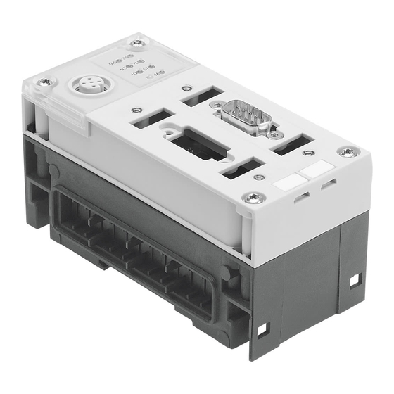
The CPX field bus node may be damaged if it is not handled correctly. Observe the regulations for handling electrostatically · sensitive components. Discharge yourself electrostatically before fitting or re · moving components in order to protect the components against discharges of static electricity. 1−3 Festo P.BE−CPX−FB11−EN en 0503b... - Page 20 Fig. 1/1: Connecting and display elements on the CPX field bus node The field bus connection is exchangeable. The following connection possibilities are available: Micro Style connection type FBA−2−M12−5POL (2 x M12) Open Style connection type FBA−1−SL−5POL with terminal strip type FBSD−KL−2x5POL 9−pin sub−D plug 1−4 Festo P.BE−CPX−FB11−EN en 0503b...
- Page 21 2. Tighten the screws at first only by hand. Place the screws so that the self−cutting threads can be used. Tighten the screws with a Torx screwdriver size T10 with 0.9 ... 1.1 Nm. 1−5 Festo P.BE−CPX−FB11−EN en 0503b...
-
Page 22: Setting The Cpx Field Bus Node
1. Place the cover carefully on the node. Please note Make sure that the seal is seated correctly. 2. Tighten both fastening screws at first by hand and then with torque 0.5 ... 0.8 Nm. 1−6 Festo P.BE−CPX−FB11−EN en 0503b... -
Page 23: Setting The Dil Switches
4. Set the diagnostic mode (lower right 2−position DIL switch). 5. Assign an unused station number to the CPX terminal. Set the desired station number (8−position DIL switch, elements 1...6). 6. Fit the cover again (chapter 1.2.1). 1−7 Festo P.BE−CPX−FB11−EN en 0503b... - Page 24 Diagnosis mode or number of I/O bytes DIL switch 4: Baud rate DIL switch 5: Station number Fig. 1/3: DIL switches in the field bus node (further information on 1 ... 5 on the following pages) 1−8 Festo P.BE−CPX−FB11−EN en 0503b...
- Page 25 (one EDS file for each module type) Tab. 1/2: DIL switch 1 (EDS mode) Please note If you configure the CPX terminal with modular EDS, the field bus node must be installed as module 0 on the first place. 1−9 Festo P.BE−CPX−FB11−EN en 0503b...
- Page 26 Polled" connection or a Change of State" connection. The 8 status bits lie in the lower−value 8 bits. The higher−value 8 bits remain unused. Tab. 1/3: DIL switch 3 (diagnosis mode or number of I/O bytes with remote controller) 1−10 Festo P.BE−CPX−FB11−EN en 0503b...
- Page 27 If no baud rate is recognised in the switch−on phase, 125 KBd will be set automatically. First connect the CPX terminal to the running DeviceNet network. Then switch on the power supply for the CPX terminal. Tab. 1/4: DIL switch 4 (baud rate) 1−11 Festo P.BE−CPX−FB11−EN en 0503b...
- Page 28 Protocol Address designation Permitted station numbers DeviceNet Station number 0...63 Tab. 1/5: Permitted station numbers Recommendation: Assign the station numbers in ascending order. Assign the station numbers to suit the machine structure of your system. 1−12 Festo P.BE−CPX−FB11−EN en 0503b...
- Page 29 Station number 38 1 + 4 = 5 2 + 4 + 32 = 38 Tab. 1/6: Examples of set station numbers The following pages contain a summary of the settings for the station numbers. 1−13 Festo P.BE−CPX−FB11−EN en 0503b...
- Page 30 1. Installation tion tion Tab. 1/7: Setting station numbers 0...31: Position of the DIL switch elements 1−14 Festo P.BE−CPX−FB11−EN en 0503b...
- Page 31 1. Installation tion tion Tab. 1/8: Setting station numbers 32...63: Position of the DIL switch elements 1−15 Festo P.BE−CPX−FB11−EN en 0503b...
-
Page 32: Connecting To The Field Bus
If the CPX terminal is fitted onto the moving part of a machine, the field bus cable on the moving part must be provided with strain relief. Please observe also the relevant regulations in EN 60204 part 1. 1−16 Festo P.BE−CPX−FB11−EN en 0503b... -
Page 33: Field Bus Baud Rate And Field Bus Length
100 m 39 m Tab. 1/9: Maximum field bus and branch line lengths depending on the baud rate (as per ODVA specification V 2.0) Information on setting the baud rate can be found in chapter 1.2.2. 1−17 Festo P.BE−CPX−FB11−EN en 0503b... -
Page 34: Connection Instructions For Devicenet
CPX terminal (pin 2 with the Micro Style connection or pin 5 with the Open Style connection): = 30.0 V DC = 11.0 V DC Recommendation: Place the power unit approximately in the centre of the bus. 1−18 Festo P.BE−CPX−FB11−EN en 0503b... - Page 35 1 2 3 4 5 Tab. 1/10: Connection diagram for DeviceNet Connect the field bus cable of your control system to the field bus interface of the CPX terminal as described in the follow ing sections. 1−19 Festo P.BE−CPX−FB11−EN en 0503b...
-
Page 36: Micro Style Connection (2 X M12)
The M12 plug serves for connecting the incoming field bus cable. The M12 plug serves for connecting the continuing field bus cable. Accessories from Festo for the Micro Style connection: M12 plug type FBS−M12−5GS−PG9 M12 socket type FBSD−GD−9−5POL Please note Use blanking plugs to seal unused connections. -
Page 37: Open Style Connection (Screw Terminals, Ip20)
Tab. 1/12: Pin assignment of the field bus interface (Open Style connection, 5−pin) If you connect the field bus via the terminal strip type FBSD−KL−2x5POL from Festo, you can implement a T−tap function (double row of screw terminals). 1−21 Festo P.BE−CPX−FB11−EN en 0503b... -
Page 38: Example Of Connection
Micro Style connection with T−tap Branch line function (if the Micro Style connection Field bus is removed completely with the plugs) Power supply T−adapter Screen Fig. 1/5: Structure of the bus interface and example of connection 1−22 Festo P.BE−CPX−FB11−EN en 0503b... -
Page 39: Further Connection Possibility Via The Sub−D Connection
The screening connection at pin 5 of the Sub−D plug is capacitively connected to the housing within the CPX terminal. This prevents equalising currents from flowing via the screening of the field bus cable (see Fig. 1/6). 1−23 Festo P.BE−CPX−FB11−EN en 0503b... - Page 40 A floating screening connection is intended with the field bus plugs from Festo. Please note The cable clip in the Festo field bus plug is connected inter nally only capacitively with the metal housing of the sub−D plug. This is to prevent equalising currents flowing through the screening of the field bus cable (Fig.
- Page 41 Field bus continuing strap Pin assignment in the field bus plug Blanking plug if connection is not used Only connected capacitively Fig. 1/7: Field bus plug from Festo type FBS−SUB−9−BU−2x5POL−B, pin assignment and screening connection 1−25 Festo P.BE−CPX−FB11−EN en 0503b...
- Page 42 Screening connection, cable clip Only connected capacitively CPX field bus node Pin assignment in the field bus plug BF PS Fig. 1/8: Field bus plug from Festo type FBS−SUB−9−BU−2x4POL, pin assignment and screening connection 1−26 Festo P.BE−CPX−FB11−EN en 0503b...
-
Page 43: Bus Termination With Terminating Resistors
CAN_L and CAN_H. Fig. 1/9 shows this as an example with the Open Style connection. Resistor for bus termination (121 ±1 %, 0.25 W) Fig. 1/9: Bus termination with resistor on the Open Style connection 1−27 Festo P.BE−CPX−FB11−EN en 0503b... -
Page 44: Pin Assignment Of Power Supply
The current consumption of a CPX terminal depends on the number and type of integrated modules and components. Read the information on power supply as well as on the earthing measures to be carried out in the CPX system manual. 1−28 Festo P.BE−CPX−FB11−E N en 0503b... - Page 45 5: 24 V / 24 V 5: 24 V 7/8"−5PIN : Operating voltage for electronics/sensors EL/SEN Load voltage outputs Load voltage valves Tab. 1/14: Pin assignment for system supply, additional supply and valve supply 1−29 Festo P.BE−CPX−FB11−E N en 0503b...
- Page 46 1. Installation 1−30 Festo P.BE−CPX−FB11−E N en 0503b...
- Page 47 Commissioning Chapter 2 2−1 Festo P.BE−CPX−FB11−EN en 0503b...
- Page 48 ......2−56 Commissioning the CPX terminal on the DeviceNet ....2−57 2−2 Festo P.BE−CPX−FB11−EN en 0503b...
-
Page 49: Commissioning
EDS (see section 2.1.2). Setting modular EDS If you wish to use modular EDS, set the EDS mode to modular EDS with the DIL switch 1 (see section 1.2.2). 2−3 Festo P.BE−CPX−FB11−EN en 0503b... -
Page 50: Ascertaining The Address Range
Some modules are in preparation Number of inputs can be switched between 2 and 4 Module identifier in the handheld With modular EDS, 8 bit always assigned Tab. 2/1: Overview of electric CPX modules (part 1) 2−4 Festo P.BE−CPX−FB11−EN en 0503b... - Page 51 MPA2 pneumatic module (type 32) VMPA2−FB−EMG−4 MPA2G with electrical isolation Some modules are in preparation Module identifier in the handheld Type of electronic module used Tab. 2/3: Overview of pneumatic modules and pneumatic interfaces (part 1) 2−5 Festo P.BE−CPX−FB11−EN en 0503b...
- Page 52 The address assignment within the pneumatic modules can be found in the manual for the valve terminal pneumatics. Further information on MPA pneumatic modules can be found in the manual for the CPX−EA modules (P.BE−CPX−EA−...). 2−6 Festo P.BE−CPX−FB11−EN en 0503b...
- Page 53 Sum of 1 to 14: _____ I _____ O Only for configuration with classical EDS file. For modular EDS, these modules occupy 8 I or O (4 are unused). Tab. 2/5: Calculating the number of inputs/outputs 2−7 Festo P.BE−CPX−FB11−EN en 0503b...
-
Page 54: Address Assignment Of The Cpx Terminal
The field bus node counts as a module with 0 inputs and 0 outputs if the status bits and the I/O diagnostic inter face are deactivated. The I/Os of various module types are assigned separately from each other. The following order applies: 2−8 Festo P.BE−CPX−FB11−EN en 0503b... - Page 55 Status bits and /I/O diagnostic interface deactivated Module no.: 0 Field bus node CPX−FB11 MPA1 pneumatic modules (each 8DO) MPA pneumatic interface MPA2 pneumatic modules (each 4DO) Fig. 2/1: Example terminal 1 (with MPA1 and MPA2 pneumatics) 2−9 Festo P.BE−CPX−FB11−EN en 0503b...
- Page 56 Tab. 2/7: Addressing the example terminal 1 (see Fig. 2/1) When modular EDS is used, the addresses are assigned bytewise. In the above example, the output addresses change starting with modules 2, 5 and 6. 2−10 Festo P.BE−CPX−FB11−EN en 0503b...
- Page 57 Field bus node CPX−FB11 Sensor CPV valve island (16DO) on the Cylinder CP interface (branch 1) CP output module (16DO) on the CP input module (16DI) CP interface (branch 4) Fig. 2/2: Example terminal 2 (with CP interface) 2−11 Festo P.BE−CPX−FB11−EN en 0503b...
- Page 58 MPA1 pneumatic O140 ... O147 O144 ... O151 module (8DO) MPA1 pneumatic O148 ... O155 O152 ... O159 module (8DO) 8 bits occupied 4 bits used Tab. 2/8: Addressing the example terminal 2 (see Fig. 2/2) 2−12 Festo P.BE−CPX−FB11−EN en 0503b...
- Page 59 Field bus node CPX−FB11 CPA pneumatics (with DIL 3.2 to ON for status bits) Pneumatic interface (set with DIL switch to 1...8 valve coils) Fig. 2/3: Example terminal 3 (with analogue module and CPA pneumatics) 2−13 Festo P.BE−CPX−FB11−EN en 0503b...
- Page 60 CPX−2AA CPA pneumatic O44 ... O51 O48 ... O55 interface set with DIL switch to 1 ...8 valve coils 8 bits occupied 4 bits used Tab. 2/9: Addressing the example terminal 3 (see Fig. 2/3) 2−14 Festo P.BE−CPX−FB11−EN en 0503b...
-
Page 61: Address Assignment After Extension/Conversion
(see pneumatics manual). Additional manifold bases (CPA) or connection bases (Midi/Maxi) are inserted between existing bases. Status bits or the I/O diagnostic interface are activated/ deactivated. 2−15 Festo P.BE−CPX−FB11−EN en 0503b... - Page 62 Changed: Pneumatic interface (now set now with activated I/O diagnosis with DIL switch to 1...16 valve coils) interface Changed: 8DI module replaced by 4DI module Fig. 2/4: Example terminal 3 after expansion/conversion (compare with Fig. 2/3) 2−16 Festo P.BE−CPX−FB11−EN en 0503b...
- Page 63 O60 ... O75 O64 ... O79 interface set with DIL switch to 1...16 valve coils 8 bits occupied 4 bits used, bold = changed module Tab. 2/10: Addressing the example terminal 3 after expansion/conversion (see Fig. 2/4) 2−17 Festo P.BE−CPX−FB11−EN en 0503b...
-
Page 64: Bus Configuration
Configuration of the CPX terminal requires a very accurate procedure, as different configuration specifications may be necessary for each slave on the DeviceNet, due to the modu lar structure. Note here the specifications in the sections which follow. 2−18 Festo P.BE−CPX−FB11−EN en 0503b... -
Page 65: Switching On The Power Supply
Or switch on the power supply in the following sequence: 1. the power supply for the bus interface 2. the power supply for all the field bus slaves 3. the power supply for the controller. 2−19 Festo P.BE−CPX−FB11−EN en 0503b... -
Page 66: Configuring Devicenet Slave Features (Eds)
1. Download the packed file from the Internet. 2. Unpack the EDS and icon files contained in the file into a directory of your choice. 3. Install the files with your configuration program (see below). 2−20 Festo P.BE−CPX−FB11−EN en 0503b... - Page 67 Symbol files Depending on the configuration program used, you can as sign symbol files (format .ico or .bmp) to the CPX terminal. The CPX terminal will then be represented accordingly in the configuration program. 2−21 Festo P.BE−CPX−FB11−EN en 0503b...
- Page 68 (format .ico) to the CPX terminal or CPX modules. The CPX terminal or the modules will then be represented accordingly in the configuration program. You will find information on the installation of EDS files and symbol files in your configuration program’s documentation. 2−22 Festo P.BE−CPX−FB11−EN en 0503b...
- Page 69 CPX terminal is not possible. When the EDS library has been extended, the CPX terminal is entered in the slave list as a possible DeviceNet slave. It can now be added to a network. 2−23 Festo P.BE−CPX−FB11−EN en 0503b...
-
Page 70: Remarks On Configuration On The Devicenet
CPX terminal: Polled Communication" Change of State / Cyclic" In addition to these communication connections, a Strobed I/O" connection must be used in each case for transmitting the status bits. 2−24 Festo P.BE−CPX−FB11−EN en 0503b... -
Page 71: Configuration With Rsnetworx For Devicenet With Standard Eds
EDS file. After instal ling the EDS−file, you will find the CPX terminal in the Hard ware" list. By shifting the mouse, you can insert slaves in the network on the right−hand side. 2−25 Festo P.BE−CPX−FB11−EN en 0503b... - Page 72 2. Commissioning CPX terminal with field bus node CPX−FB11 (standard EDS) Fig. 2/5: Hardware list and network in RSNetWorx for DeviceNet with standard EDS 2−26 Festo P.BE−CPX−FB11−EN en 0503b...
- Page 73 1. Double−click the desired scanner in the network. A dialogue box will open. 2. Select the Scanlist" register and assign the existing slaves to the scanner. Button for assigning the slave Fig. 2/6: Scanlist" register (example) 2−27 Festo P.BE−CPX−FB11−EN en 0503b...
- Page 74 Communication type Strobed" for diagnosis information Status bits (1 input byte) Communication type Polled" for I/O data: 4 input bytes for status bits and CPX input modules, 7 output bytes for CPX output modules and the pneu matic interface. 2−28 Festo P.BE−CPX−FB11−EN en 0503b...
- Page 75 The CPX terminal appears in the input data with two separate communication connections: A Strobed" connection for transmitting the 8 status bits (diagnostic information). A Polled" or Change of State" connection for transmit ting the physical input data. 2−29 Festo P.BE−CPX−FB11−EN en 0503b...
- Page 76 Polled": Fig. 2/9: Address assignment of the output (example) Load the configuration into the scanner Finally, load the configuration data into the scanner. Further information can be found in the documentation for the scanner. 2−30 Festo P.BE−CPX−FB11−EN en 0503b...
- Page 77 Field bus node CPX−FB11 CPA pneumatics (with DIL 3.2 to ON for status bits) Pneumatic interface (set with DIL switch to 1...8 valve coils) Fig. 2/10: CPX example terminal 3 (address example for scanner 1747−SDN, see following table) 2−31 Festo P.BE−CPX−FB11−EN en 0503b...
- Page 78 O1.2.0 ... O1.2.15 CPA pneumatic interface set with O1.3.12 ... O1.3.15 DIL switch to 1...8 valve coils O1.4.0 ... O1.4.3 Tab. 2/15: Addressing example for scanner 1747−SDN with CPX example terminal 3 and standard EDS 2−32 Festo P.BE−CPX−FB11−EN en 0503b...
-
Page 79: Configuration With Rsnetworx For Devicenet With Modular Eds
CPX−FB11 Modular RIO Status bits" CPX terminal with status bits With the mouse, pull the corresponding entry into the network on the right−hand side. This configuration must correspond to the setting of the DIL switch 3 (see Tab. 1/3). 2−33 Festo P.BE−CPX−FB11−EN en 0503b... - Page 80 2. Commissioning CPX terminal with field bus node CPX−FB11 for modular EDS CPX terminal in the network Fig. 2/11: Hardware list and network in RSNetWorx for DeviceNet (modular EDS) 2−34 Festo P.BE−CPX−FB11−EN en 0503b...
- Page 81 1. Double−click the desired scanner in the network. A dialogue box will open. 2. Select the Scanlist" register and assign the existing slaves to the scanner. Button for assigning the slave Fig. 2/12: Scanlist" register (example) 2−35 Festo P.BE−CPX−FB11−EN en 0503b...
- Page 82 3. Pull the CPX module in accordance with your CPX ter minal’s equipment into the configuration table on the right−hand side. The illustration shows the configuration for the example terminal 2 from Fig. 2/2: Fig. 2/13: Module configuration with modular EDS (example terminal 2) 2−36 Festo P.BE−CPX−FB11−EN en 0503b...
- Page 83 MPA pneumatic modules. Fig. 2/14: Display of the occupied I/O bytes (example 2, mod. EDS) The above illustration shows the position of the modules in the CPX terminal, but not the real I/O mapping! 2−37 Festo P.BE−CPX−FB11−EN en 0503b...
- Page 84 2. With the registers Input" and Output", you can assign the I/O addresses of the CPX terminal to the PLC operands. Fig. 2/15: Address assignment of the input (example 2, mod. EDS) 2−38 Festo P.BE−CPX−FB11−EN en 0503b...
- Page 85 Example: scanner 1747−SDN (SLC 500 series) Addressing for example terminal 2 (CPX terminal with CP Interface, see Fig. 2/2) with: 6 input bytes, input address as from I1.1.0 20 output bytes, output address as from O1.1.0 2−39 Festo P.BE−CPX−FB11−EN en 0503b...
- Page 86 MPA1 pneumatic module (8DO) O1.10.0 ... O1.10.7 MPA1 pneumatic module (8DO) O1.10.8 ... O1.10.15 8 bits occupied, 4 bits used Tab. 2/16: Addressing for scanner 1747−SDN with CPX example terminal 2 (see Fig. 2/2) with modular EDS 2−40 Festo P.BE−CPX−FB11−EN en 0503b...
-
Page 87: Parameterisation
(P.BE−CPX−SYS−...). The module parameters which are available for the various modules can be found in the manual for the relevant module (e.g. manual for CPX pneumatic interfaces and CPX I/O mod ules (P.BE−CPX−EA−...). 2−41 Festo P.BE−CPX−FB11−EN en 0503b... - Page 88 CPX terminal is replaced during servicing. In these cases, check before replacement to see which settings are required and carry out these settings. 2−42 Festo P.BE−CPX−FB11−EN en 0503b...
-
Page 89: Methods Of Parameterisation
(plain CPX terminal and is handheld. text). lost if the CPX ter minal is replaced. It is possible to copy the current parameter settings with the aid of the handheld. Tab. 2/17: Methods of parameterisation 2−43 Festo P.BE−CPX−FB11−EN en 0503b... - Page 90 CPX terminal after Power On. Please note If the system parameter System start" has the setting System start with saved parameterisation and saved CPX system equipment", modified parameter settings in the CPX terminal will become valid immediately after Power 2−44 Festo P.BE−CPX−FB11−EN en 0503b...
-
Page 91: Parameterisation With Rsnetworx With Standard Eds
EDS library (see section 2.2.2). The following diagram shows the Parameters" register of the CPX terminal: Fig. 2/17: Parameterisation with standard EDS The settings saved in the project are displayed in offline mode. 2−45 Festo P.BE−CPX−FB11−EN en 0503b... - Page 92 Groups" check box Parameters and data grouped in folders Set parameters with list field Buttons for online display (monitor), upload and download parameters Fig. 2/18: Selection of parameters and data with standard 2−46 Festo P.BE−CPX−FB11−EN en 0503b...
- Page 93 A detailed description of the individual parameters as well as basic information on application can be found in the CPX sys tem manual (P.BE−CPX−SYS−...). You can find notes on specific parameters of the DeviceNet in section 2.3.4. 2−47 Festo P.BE−CPX−FB11−EN en 0503b...
-
Page 94: Parameterisation With Rsnetworx With Modular Eds
CPX terminal. Double clicking on the module in the configuration table brings you to the window for setting the parameters. Buttons for upload and download of System parameters and data the parameters Module parameters Fig. 2/19: Parameterisation with modular EDS 2−48 Festo P.BE−CPX−FB11−EN en 0503b... - Page 95 Double−click on the field bus node in the configuration · table. Set the system parameters in the displayed window in the Configuration Settings" register. Confirm twice with OK. Set parameters with list field Fig. 2/20: System parameters and data with modular EDS 2−49 Festo P.BE−CPX−FB11−EN en 0503b...
- Page 96 In online mode the settings of the CPX terminal will be transmitted and displayed when accessed. Transmission of the values requires a certain amount of time. Current values are continuously displayed only in monitor mode. However, there is no detail representation. 2−50 Festo P.BE−CPX−FB11−EN en 0503b...
-
Page 97: Notes On Specific Parameters Of The Devicenet
Tab. 2/18: Possible states in the Idle mode You can determine the status to be assumed for each output channel (output or solenoid coil) separately. The standard setting is Reset output channel". Further information can be found in the CPX system manual. 2−51 Festo P.BE−CPX−FB11−EN en 0503b... - Page 98 Available Devices", mark the CPX terminal. 4. Under ADR Settings", choose the setting Configuration Recovery". The scanner then automatically loads the set parameters into the CPX terminal before it exchanges I/O data with the CPX terminal. 2−52 Festo P.BE−CPX−FB11−EN en 0503b...
- Page 99 2. Commissioning Setting [Configuration Recovery] Fig. 2/22: Setting for automatic parameterisation after Power on 2−53 Festo P.BE−CPX−FB11−EN en 0503b...
-
Page 100: Parameterisation Via The Plc User Program
1 ... 12 Diagnostic trace object SINT 1 ... 13 Diagnosis of trace status object (various) Tab. 2/19: Object classes for standard EDS (overview) Detailed object descriptions for standard EDS can be found in appendix B.1. 2−54 Festo P.BE−CPX−FB11−EN en 0503b... - Page 101 1 ... 12 Diagnosis of trace object USINT/BYTE 1 ... 13 Diagnosis of trace status object (various) Tab. 2/20: Object classes for modular EDS (overview) Detailed object descriptions for modular EDS can be found in appendix C.1. 2−55 Festo P.BE−CPX−FB11−EN en 0503b...
-
Page 102: Parameterisation With The Handheld
2. Commissioning 2.3.6 Parameterisation with the handheld The CPX handheld offers menu−orientated access to para meterise the CPX terminal without configuration software. Information on operating the handheld can be found in the relevant manual. 2−56 Festo P.BE−CPX−FB11−EN en 0503b... -
Page 103: Commissioning The Cpx Terminal On The Devicenet
CPX terminal is replaced, the new terminal will also be operated with the desired parameter settings. Use spot checks if necessary to check the parameterisa · tion, e.g. with the configuration program or with the hand held. 2−57 Festo P.BE−CPX−FB11−EN en 0503b... - Page 104 2. Commissioning 2−58 Festo P.BE−CPX−FB11−EN en 0503b...
-
Page 105: Diagnosis And Error Treatment
Diagnosis and error treatment Chapter 3 3−1 Festo P.BE−CPX−FB11−EN en 0503b... - Page 106 ..........3−23 3−2 Festo P.BE−CPX−FB11−EN en 0503b...
-
Page 107: Overview Of Diagnostic Options
CPX hand recognition of faults handheld held in a user−friendly manner by means of menus. Tab. 3/1: Diagnostic possibilities Please note Note that the diagnostic information displayed depends on the parameterisation of the CPX terminal. 3−3 Festo P.BE−CPX−FB11−EN en 0503b... -
Page 108: Diagnosis Via Leds
CPX field bus node. CPX−specific LEDs PS: power system PL: power load SF: system fault M: modify DeviceNet−specific LEDs MS: module status NS: network status IO: I/O status Fig. 3/1: LEDs on the CPX field bus node CPX−FB11 3−4 Festo P.BE−CPX−FB11−EN en 0503b... - Page 109 The following LEDs Standard light up green: The SF LED does not light up. M LED see function number 4402 Lights up only when inputs/outputs are controlled via DeviceNet. Tab. 3/2: Normal operating status 3−5 Festo P.BE−CPX−FB11−EN en 0503b...
-
Page 110: Cpx−Specific Leds
PL (Power Load) power load supply (outputs/valves) LED (green) Sequence Status Meaning/fault treatment No fault. Load voltage None applied LED lights up Load voltage at the system Eliminate undervoltage supply or additional supply outside the tolerance LED flashes range 3−6 Festo P.BE−CPX−FB11−E N en 0503b... - Page 111 The system fault LED flashes depending on the class of fault which has occurred. Fault class 1 (simple fault): flash once, pause Fault class 2 (fault): flash twice, pause Fault class 3 (serious fault): flash three times, pause 3−7 Festo P.BE−CPX−FB11−E N en 0503b...
- Page 112 The Force function is enabled (see system parameter Force mode", function no. 4402). LED flashes The display of the Force function (LED flashes) has precedence over the display of the setting for System start (LED lights up). 3−8 Festo P.BE−CPX−FB11−E N en 0503b...
- Page 113 Complete or correct the configuration flashes red Fault cannot be rectified Check equipment on CPX as well as other LEDs and, if necessary, request service lights up red CPX terminal is in self−test None flashes red−green 3−9 Festo P.BE−CPX−FB11−E N en 0503b...
- Page 114 Flashes failed". red/green Test algorithm which ensures that station numbers on the network are not assigned twice. The test is usually carried out automatically when the network connection is set up. 3−10 Festo P.BE−CPX−FB11−E N en 0503b...
- Page 115 One or several outputs are Check the other LEDs, if necessary forcibly switched off (per request servicing haps a fault which cannot be corrected); one or more lights up red inputs have a fault which cannot be corrected. 3−11 Festo P.BE−CPX−FB11−E N en 0503b...
-
Page 116: Diagnosis Via Status Bits
If various faults occur simultaneously on various types of modules, these faults cannot be assigned via the status bits. Faults can be clearly defined via the I/O diagnostic interface of by diagnosis via DeviceNet access. 3−12 Festo P.BE−CPX−FB11−E N en 0503b... -
Page 117: Diagnosis Via I/O Diagnostic Interface
If the I/O diagnostic interface is active, it will occupy the first 16 inputs and outputs in the address range. Instructions on diagnosis with the I/O diagnostic interface can be found in the CPX system manual. 3−13 Festo P.BE−CPX−FB11−E N en 0503b... -
Page 118: Diagnosis Via Devicenet
1. Make sure that the field bus node is online on the DeviceNet. 2. Double click on the symbol of the CPX terminal in the software configurator (e.g. RSNetWorx). 3. Click on the Parameters" register. 3−14 Festo P.BE−CPX−FB11−E N en 0503b... - Page 119 Groups with diagnostic data Detailed information on parameters and data can be found in appendix A.3 and in the CPX system manual. The following diagram shows as an example the system diagnostic data in the group SysDiag.Data. 3−15 Festo P.BE−CPX−FB11−E N en 0503b...
- Page 120 CPX system (irrespective of the module type). The equipment fitted on the CPX ter minal must be known before the relevant module diagnostic data can be ascertained (see following example). 3−16 Festo P.BE−CPX−FB11−E N en 0503b...
- Page 121 16 O Ó Ó Ó Ó Ó Ó Ó Ó First digital module Third digital module (digital module 2) (digital module 0) Second digital module (digital module 1) Fig. 3/3: Numbering the modules (example) 3−17 Festo P.BE−CPX−FB11−E N en 0503b...
-
Page 122: Diagnosis Via Software Configurator With Modular Eds
(module 0, see also Fig. 2/13). 5. In the window now appearing, double click on the Configuration Settings" tab (Fig. 3/4): Diagnosis information (double click for detailed display) Fig. 3/4: Online diagnosis via the software configurator (modular EDS) 3−18 Festo P.BE−CPX−FB11−E N en 0503b... - Page 123 3. Diagnosis and error treatment 6. For detailed diagnosis information, double−click on the appropriate line (1 in Fig. 3/4). Fig. 3/5: Detailed diagnosis information 3−19 Festo P.BE−CPX−FB11−E N en 0503b...
-
Page 124: Diagnosis Via The User Program
Module (100 or 102 the faulty channel Tab. 3/6: Possible sequence of diagnosis A description of the possible fault numbers can be found in chapter 5 of the system manual. 3−20 Festo P.BE−CPX−FB11−E N en 0503b... - Page 125 Number of entries in the diagnostic memory status object Trace status Diagnostic trace Long−term memory (max. 40 entries) object Detail diagnosis + relative time stamp per fault event Tab. 3/7: Diagnosis data standard EDS 3−21 Festo P.BE−CPX−FB11−E N en 0503b...
- Page 126 Number of entries in the diagnostic memory status object Trace status Diagnostic trace Long−term memory (max. 40 entries) object Detail diagnosis + relative time stamp per fault event Tab. 3/8: Diagnosis data modular EDS 3−22 Festo P.BE−CPX−FB11−E N en 0503b...
-
Page 127: Fault Treatment
Single−solenoid valves move to the basic position. Double−solenoid valves remain in the current position. Mid−position valves move to the mid−position (depend ing on valve type: pressurised, exhausted or blocked). 3−23 Festo P.BE−CPX−FB11−E N en 0503b... - Page 128 3. Diagnosis and error treatment 3−24 Festo P.BE−CPX−FB11−E N en 0503b...
- Page 129 Technical appendix Appendix A A−1 Festo P.BE−CPX−FB11−EN en 0503b...
-
Page 130: A. Technical Appendix
Numbering the modules in the standard EDS file ....A−8 A.4.2 Channel assignment for Force, Fail safe and Idle parameters ..A−10 A−2 Festo P.BE−CPX−FB11−EN en 0503b... -
Page 131: A.1 Technical Specifications Of Field Bus Node Type Cpx−Fb11
Baud rate 125 kBaud, 250 kBaud, 500 kBaud Cable type See DeviceNet specification part 1, appendix B and installation guidelines for your controller Cable length (depends on baud rate and cable type) Max. 500 m A−3 Festo P.BE−CPX−FB11−EN en 0503b... -
Page 132: A.2 Accessories For Field Bus Connection
Tab. A/1: Accessories for field bus connection If you wish to use 9−pin Sub−D plugs of other manufacturers, you must replace the two flat screws on the plug with threaded sockets (part no. 340 960). A−4 Festo P.BE−CPX−FB11−EN en 0503b... -
Page 133: A.3 Eds Files Of The Cpx Terminal For Standard Eds
9 digital modules, 9 analogue modules In the file names DE stands for German, EN for English. This EDS file supports all possible module combinations. Tab. A/2: EDS files for the CPX terminal (standard EDS) A−5 Festo P.BE−CPX−FB11−EN en 0503b... -
Page 134: A.4 Structure Of The Standard Eds Files
Idle parameter digital output modules Force Param AO Force parameter analogue output module FailSafe Param AO Fail safe parameter analogue output module Idle Param AO Idle parameter analogue output module Force Param AI Force parameter analogue input module A−6 Festo P.BE−CPX−FB11−EN en 0503b... - Page 135 (P.BE−CPX−SYS−...). The module parameters which are available for the various modules can be found in the manual for the relevant module (e.g. manual for CPX pneumatic interfaces and CPX I/O mod ules (P.BE−CPX−EA−...). A−7 Festo P.BE−CPX−FB11−EN en 0503b...
-
Page 136: A.4.1 Numbering The Modules In The Standard Eds File
CPX terminal. It is not identical to the module position number (see also Fig. A/1). The digital modules and the analogue modules are counted separately in each case from left to right, beginning with zero. A−8 Festo P.BE−CPX−FB11−EN en 0503b... - Page 137 Pneumatic interface (PI Mod) Second digital module (digital mod. 1) First analogue module (analog mod. 0) Third digital module (digital module 2) Second analogue module (ana. mod. 1) Fig. A/2: Numbering the modules (example with CPA pneumatics) A−9 Festo P.BE−CPX−FB11−EN en 0503b...
-
Page 138: A.4.2 Channel Assignment For Force, Fail Safe And Idle Parameters
Channel type identifier in group names The following pictures show as an example the assignment of the digital force outputs. The digital modules and the analogue modules are counted separately in each case from left to right. A−10 Festo P.BE−CPX−FB11−EN en 0503b... - Page 139 A. Technical appendix 4DO 8DI 8DO Number of the output word Bit number Fig. A/3: Assignment of the digital force outputs (example MPA pneumatics) A−11 Festo P.BE−CPX−FB11−EN en 0503b...
- Page 140 Ó Ó Ó Ó Number of the output word Bit number Fig. A/4: Assignment of the digital force outputs (example CPA pneumatics) The diagram below shows as an example the assignment of the analogue force outputs. A−12 Festo P.BE−CPX−FB11−EN en 0503b...
- Page 141 Ó Ó Ó Ó Ó Ó Ó Ó Ó Ó Ó Ó Ó Ó Ó Ó Analogue channel 0 + 1 Analogue channel 2 + 3 Fig. A/5: Assignment of the analogue force outputs (example) A−13 Festo P.BE−CPX−FB11−EN en 0503b...
- Page 142 A. Technical appendix A−14 Festo P.BE−CPX−FB11−EN en 0503b...
- Page 143 DeviceNet objects with Standard EDS Appendix B B−1 Festo P.BE−CPX−FB11−EN en 0503b...
-
Page 144: B. Devicenet Objects With Standard Eds
B.1.15 Diagnostic trace status object ......B−27 B−2 Festo P.BE−CPX−FB11−EN en 0503b... -
Page 145: Devicenet Objects With Standard Eds
8−bit input data General parameters Object Message Assembly Assembly Router Assembly Inputs outputs Diagnostic byte Diagnostic trace object Explicit Connection Message Connection Diagnostic trace status object Fig. B/1: DeviceNet object model of the CPX terminal B−3 Festo P.BE−CPX−FB11−EN en 0503b... -
Page 146: Overview
Service Code Service Name 05 (0x05) Reset 14 (0x0E) Get Attribute Single 16 (0x10) Set Attribute Single 75 (0x4B) Allocate Group 2 Identifier Set 76 (0x4C) Release Group 2 Identifier Set B−4 Festo P.BE−CPX−FB11−EN en 0503b... - Page 147 The description of the functions of the individual parameters and data as well as the fundamentals of parameterisation can be found in the CPX system manual. B−5 Festo P.BE−CPX−FB11−EN en 0503b...
-
Page 148: Module−Parameter Object
Not all the attributes of this object exist as parameters in all module types. Information on the parameters, and thereby on the attributes which a module supports, can be found in the manual for the relevant module. B−6 Festo P.BE−CPX−FB11−EN en 0503b... - Page 149 2008 + m * 4 + 0 Channel 0 (bit 0 ... 5) 63: Channel 63 Module fault number (see System manual USINT 2008 + m * 4 + 1 chapter 5 Possible fault numbers") (bit 0 ... 7) B−7 Festo P.BE−CPX−FB11−EN en 0503b...
- Page 150 Get/Set Input debouncing time (value range 0 ... 3) USINT 4828 + m * 64 + 1 0: 0.1 ms (bits 4, 5) 1: 3 ms (typical presetting) 2: 10 ms 3: 20 ms B−8 Festo P.BE−CPX−FB11−EN en 0503b...
- Page 151 SINT Get/Set 32. Byte parameter of the module SINT Get/Set 1. Word parameter of the module Get/Set 16. Word parameter of the module Get/Set 1. Double word parameter DINT Get/Set 8. Double word parameter DINT B−9 Festo P.BE−CPX−FB11−EN en 0503b...
- Page 152 1st. byte parameter of object 100 (attribute 119). Pneumatic interface 1st parameter (32 bits): Activate monitoring wire fracture channel−by−channel; placing in the 1st./2nd./3rd./4th. byte parameter of object 100 (attributes 119, 120, 121 and 122). B−10 Festo P.BE−CPX−FB11−EN en 0503b...
-
Page 153: B.1.4 Assembly Object Instances
Object instances of the analogue channels (16−bit orientated) Instances of the function modules (16−bit orientated) Object instances of the digital outputs (8−bit orientated) Each new data range begins on the LSB (least significant bit) of a word. B−11 Festo P.BE−CPX−FB11−EN en 0503b... - Page 154 Object instances of the analogue channels (16−bit orientated) Instances of the function modules (16−bit orientated) Object instances of the digital inputs (8−bit orientated) Each new data range begins on the LSB (least significant bit) of a word. B−12 Festo P.BE−CPX−FB11−EN en 0503b...
- Page 155 Digital data 8 bits Transmission by communication types Polled I/O or COS/Cyclic. Instance 102: SYSTEM STATUS Instance 102 (system status) possesses the following member list: Entries in member list Orient. Obj. Status byte 8 bits B−13 Festo P.BE−CPX−FB11−EN en 0503b...
-
Page 156: Channel Assignment For Force, Fail Safe And Idle Parameters
The first word receives the lowest instance number of the relevant object. The second word receives the second lowest instance number etc. Further instructions on assigning the Force, Fail safe and Idle parameters can be found in section A.4.2. B−14 Festo P.BE−CPX−FB11−EN en 0503b... -
Page 157: Object, Modification Digital Outputs
Fault state parameter for output word n WORD Get/Set Idle mode parameter for output word n WORD Get/Set Idle state parameter for output word n WORD Identical with the assignment of the data block of the digital outputs B−15 Festo P.BE−CPX−FB11−EN en 0503b... -
Page 158: Object, Modification Digital Inputs
Attr. no. Access Description Type Function no. Get/Set Force mode parameter for input word n WORD Get/Set Force state parameter for input word n WORD Identical with the assignment of the data block of the digital inputs B−16 Festo P.BE−CPX−FB11−EN en 0503b... -
Page 159: Object, Modification Analogue Outputs
Idle mode of the relevant channel USINT Get/Set Idle state of the relevant channel Identical with the distribution of the data block of the analogue output data. The value is congruent with the value of the analogue output channel. B−17 Festo P.BE−CPX−FB11−EN en 0503b... -
Page 160: Object, Modification Analogue Inputs
Force mode of the relevant channel USINT Get/Set Force state of the relevant channel Identical with the distribution of the data block of analogue input data. The value is congruent with the value of the analogue input channel. B−18 Festo P.BE−CPX−FB11−EN en 0503b... -
Page 161: Object, Modification Output Words Function Module
Fault state parameter for output word n WORD Get/Set Idle mode parameter for output word n WORD Get/Set Idle state parameter for output word n WORD Identical with the distribution of the data block of the function output data. B−19 Festo P.BE−CPX−FB11−EN en 0503b... -
Page 162: Object, Modification Input Words Function Module
Description Type Function no. Get/Set Force mode parameter for input word n WORD Get/Set Force state parameter for input word n WORD Identical with the distribution of the data block of the function input data. B−20 Festo P.BE−CPX−FB11−EN en 0503b... -
Page 163: Module−Independent System Object
Specifies how the system start of the CPX terminal is to be carried out 0: System start with default parameterisation (factory setting) and current CPX equip ment status 1: System start with saved parameterisation and saved CPX equipment status B−21 Festo P.BE−CPX−FB11−EN en 0503b... - Page 164 From the module number you can ascertain the instance no. of object 100 via the relevant module type. With the aid of this instance num ber, further diagnostic data can be ascertained (e.g. the number of the faulty channel). B−22 Festo P.BE−CPX−FB11−EN en 0503b...
- Page 165 Force mode USINT 4402 (bit 2, 3) 0: Blocked 1: Enabled Get/Set Fail safe USINT 4402 (bit 0, 1) 0: Reset all outputs (presetting) 1: Hold last State (retain signal status) 2: Assume fault mode B−23 Festo P.BE−CPX−FB11−EN en 0503b...
- Page 166 Number of input bytes (Rx size) USINT Specifies the number of input bytes of the CPX terminal. Number of output bytes (Tx size) USINT Specifies the number of output bytes of the CPX terminal. Get/Set Reserved USINT Get/Set Reserved USINT B−24 Festo P.BE−CPX−FB11−EN en 0503b...
-
Page 167: Status And Diagnostic Object
Bit 5: short circuit/overload Bit 6: wire fracture Bit 7: other faults Get/Set 16 output bits (order data) of the I/O diagnostic UINT interface 16 input bits (reply data) of the I/O diagnostic UINT interface B−25 Festo P.BE−CPX−FB11−EN en 0503b... -
Page 168: Diagnostic Trace Object
Measured from the moment the power supply is switched on If the fault number = 0, the contents are also 0. If the fault number lies between 128 ... 199 (fault class 3), the contents are not relevant (servicing required). B−26 Festo P.BE−CPX−FB11−EN en 0503b... -
Page 169: Diagnostic Trace Status Object
1: inactive (bit 0) 0: active (presetting) Get/Set Run/stop filter 1 USINT 3480 0: Stop after 40 entries (save the first 40 entries) (bit 1) 1: Overwrite old entries (save the last 40 entries, presetting) B−27 Festo P.BE−CPX−FB11−EN en 0503b... - Page 170 (bits 0 ... 7) Get/Set Channel number USINT 3486 Channel number for the diagnostic memory filter (bits 0 ... 7) Get/Set Fault number USINT 3487 Fault number for the diagnostic memory filter (bits 0 ... 7) B−28 Festo P.BE−CPX−FB11−EN en 0503b...
- Page 171 DeviceNet objects with Modular EDS Appendix C C−1 Festo P.BE−CPX−FB11−EN en 0503b...
-
Page 172: C. Devicenet Objects With Modular Eds
C.1.14 Diagnostic trace status object ......C−31 C−2 Festo P.BE−CPX−FB11−EN en 0503b... -
Page 173: Devicenet Objects With Modular Eds
General parameters Object Message Assembly Assembly Assembly Router outputs Diagnostic byte Inputs Diagnostic trace object Explicit Connection Message Diagnostic trace Connection status object Fig. C/1: DeviceNet object model of the CPX terminal for modular EDS C−3 Festo P.BE−CPX−FB11−EN en 0503b... -
Page 174: Overview
Service Code Service Name 05 (0x05) Reset 14 (0x0E) Get Attribute Single 16 (0x10) Set Attribute Single 75 (0x4B) Allocate Group 2 Identifier Set 76 (0x4C) Release Group 2 Identifier Set C−4 Festo P.BE−CPX−FB11−EN en 0503b... - Page 175 The description of the functions of the individual parameters and data as well as the fundamentals of parameterisation can be found in the CPX system manual. C−5 Festo P.BE−CPX−FB11−EN en 0503b...
-
Page 176: Assembly Object Instances
Object instances of the analogue channels (16−bit orientated) Instances of the function modules (16−bit orientated) Object instances of the digital outputs (8−bit orientated) Each new data range begins on the LSB (least significant bit) of a word. C−6 Festo P.BE−CPX−FB11−EN en 0503b... - Page 177 Object instances of the analogue channels (16−bit orientated) Instances of the function modules (16−bit orientated) Object instances of the digital inputs (8−bit orientated) Each new data range begins on the LSB (least significant bit) of a word. C−7 Festo P.BE−CPX−FB11−EN en 0503b...
- Page 178 Digital data 8 bits Transmission by communication types Polled I/O or COS/Cyclic. Instance 103: SYSTEM STATUS Instance 103 (system status) possesses the following member list: Entries in member list Orient. Obj. Status byte 8 bits C−8 Festo P.BE−CPX−FB11−EN en 0503b...
-
Page 179: Status And Diagnostic Object
Bit 5: short circuit/overload Bit 6: wire fracture Bit 7: other faults Get/Set 16 output bits (order data) of the I/O diagnostic UINT interface 16 input bits (reply data) of the I/O diagnostic UINT interface C−9 Festo P.BE−CPX−FB11−EN en 0503b... -
Page 180: Module−Independent System Object
Specifies how the system start of the CPX ter minal is to be carried out, 0: System start with default parameterisation (factory setting) and current CPX equipment status 1: System start with saved parameterisation and saved CPX equipment status C−10 Festo P.BE−CPX−FB11−EN en 0503b... - Page 181 100 via the relevant module type. With the aid of this instance number, further diagnostic data can be ascertained (e.g. the number of the faulty channel). C−11 Festo P.BE−CPX−FB11−EN en 0503b...
- Page 182 Force mode USINT 4402 (bit 2, 3) 0: Blocked 1: Enabled Get/Set Fail safe USINT 4402 (bit 0, 1) 0: Reset all outputs (presetting) 1: Hold last State (retain signal status) 2: Assume fault mode C−12 Festo P.BE−CPX−FB11−EN en 0503b...
- Page 183 Number of input bytes (Rx size) USINT Specifies the number of input bytes of the CPX terminal. Number of output bytes (Tx size) USINT Specifies the number of output bytes of the CPX terminal. Get/Set Reserved USINT Get/Set Reserved USINT C−13 Festo P.BE−CPX−FB11−EN en 0503b...
-
Page 184: Parameter Object Module
Newer modules from Use the general module−parameter object (see section C.1.7) mid−2005 onward to parameterise modules with word or double−word para meters. C−14 Festo P.BE−CPX−FB11−EN en 0503b... - Page 185 2008 + m * 4 + 0 Channel 0 (bit 0 ... 5) 63: Channel 63 Module fault number (see System manual USINT 2008 + m * 4 + 1 chapter 5 Possible fault numbers") (bit 0 ... 7) C−15 Festo P.BE−CPX−FB11−EN en 0503b...
- Page 186 Get/Set Input debouncing time (value range 0 ... 3) USINT 4828 + m * 64 + 1 0: 0.1 ms (bits 4, 5) 1: 3 ms (typical presetting) 2: 10 ms 3: 20 ms C−16 Festo P.BE−CPX−FB11−EN en 0503b...
- Page 187 4828 + m * 64 + 9 Get/Set Lower limit channel 0 with AI 4828 + m * 64 + 10...11 Get/Set Lower limit channel 1 with AI 4828 + m * 64 + 12...13 C−17 Festo P.BE−CPX−FB11−EN en 0503b...
- Page 188 4828 + m * 64 + 11...12 Get/Set Upper limit channel 0 with AO 4828 + m * 64 + 13...14 Get/Set Upper limit channel 1 with AO 4828 + m * 64 + 15...16 C−18 Festo P.BE−CPX−FB11−EN en 0503b...
-
Page 189: C.1.7 General Object Module Parameters
2. Look for this function no. in the last column of Tab. C/1 (byte and word parameters) or Tab. C/2 (double−word parameters). 3. Read the corresponding attribute no. from the table. You will find examples for parameterisation after the table. C−19 Festo P.BE−CPX−FB11−EN en 0503b... - Page 190 4828 + m * 64 + 61 4828 + m * 64 + 62 4828 + m * 64 + 63 Tab. C/1: General module−parameter object: assignment of attributes for word parameters to the function numbers C−20 Festo P.BE−CPX−FB11−EN en 0503b...
- Page 191 4828 + m * 64 + 61 4828 + m * 64 + 62 4828 + m * 64 + 63 Tab. C/2: General module−parameter object: assignment of attributes for double−word parameters to the function numbers C−21 Festo P.BE−CPX−FB11−EN en 0503b...
- Page 192 The following tables show how to determine the attributes for parameterisation. The parameters of the respective modules are entered into the tables. Information on the parameters can be found in the manual for the relevant module. C−22 Festo P.BE−CPX−FB11−EN en 0503b...
- Page 193 4828 + m * 64 + 16 Lower limit channel 2 4828 + m * 64 + 17 4828 + m * 64 + ... Tab. C/4: Example: Parameterisation of the lower limit (module no. 2, channel 2) C−23 Festo P.BE−CPX−FB11−EN en 0503b...
-
Page 194: Channel Assignment For Force, Fail Safe And Idle Parameters
The first word receives the lowest instance number of the relevant object. The second word receives the second lowest instance number etc. Further instructions on assigning the Force, Fail safe and Idle parameters can be found in section A.4.2. C−24 Festo P.BE−CPX−FB11−EN en 0503b... -
Page 195: C.1.9 Object: Forcing Inputs
Force mode parameter analogue inputs WORD channel 0 ... 3 168 ... 172 Get/Set Force state parameter analogue inputs WORD channel 0 ... 3 Tab. C/6: Objects for forcing inputs (grey: example for forcing from Fig. C/3) C−25 Festo P.BE−CPX−FB11−EN en 0503b... - Page 196 C. DeviceNet objects with Modular EDS Module no./ Instance no.: (0) AI−I Field bus node CPX−FB11 Parameterisation: Module CPX−4AE−I, setting force mode for channel 2: Object class 104, instance 2, attribute 166 (see Tab. C/6) Fig. C/3: Example for forcing C−26 Festo P.BE−CPX−FB11−EN en 0503b...
-
Page 197: Object: Forcing Outputs
(Technology modules, e.g. CP interface) 164 ... 167 Get/Set Force mode parameter analogue outputs WORD channel 0 ... 3 168 ... 172 Get/Set Force state parameter analogue outputs WORD channel 0 ... 3 Tab. C/7: Objects for forcing outputs C−27 Festo P.BE−CPX−FB11−EN en 0503b... -
Page 198: Object: Fault Mode And Fault State Of The Outputs
Fault mode parameter analogue outputs WORD channel 0 ... 3 168 ... 172 Get/Set Fault state parameter analogue outputs WORD channel 0 ... 3 Tab. C/8: Objects for Fault mode and Fault state of the outputs C−28 Festo P.BE−CPX−FB11−EN en 0503b... -
Page 199: Object: Idle Mode And Idle State Of The Outputs
Idle mode parameter analogue outputs WORD channel 0 ... 3 168 ... 172 Get/Set Idle state parameter analogue outputs WORD channel 0 ... 3 Tab. C/9: Objects for Idle mode and Idle state of the outputs C−29 Festo P.BE−CPX−FB11−EN en 0503b... -
Page 200: Diagnostic Trace Object
Measured from the moment the power supply is switched on If the fault number = 0, the contents are also 0. If the fault number lies between 128 ... 199 (fault class 3), the contents are not relevant (servicing required). C−30 Festo P.BE−CPX−FB11−EN en 0503b... -
Page 201: Diagnostic Trace Status Object
1: Inactive (bit 0) 0: Active (presetting) Get/Set Run/stop filter 1 USINT 3480 0: Stop after 40 entries (save the first 40 entries) (bit 1) 1: Overwrite old entries (save the last 40 entries, presetting) C−31 Festo P.BE−CPX−FB11−EN en 0503b... - Page 202 (bits 0 ... 7) Get/Set Channel number USINT 3486 Channel number for the diagnostic memory filter (bits 0 ... 7) Get/Set Fault number USINT 3487 Fault number for the diagnostic memory filter (bits 0 ... 7) C−32 Festo P.BE−CPX−FB11−EN en 0503b...
- Page 203 Index Appendix D D−1 Festo P.BE−CPX−FB11−EN en 0503b...
-
Page 204: D. Index
............D−1 D−2 Festo P.BE−CPX−FB11−EN en 0503b... - Page 205 Via status bits ....... . 3−12 D−3 Festo P.BE−CPX−FB11−EN en 0503b...
- Page 206 ......... . 3−4 D−4 Festo P.BE−CPX−FB11−EN en 0503b...
- Page 207 Switching on ....... . . 2−19 D−5 Festo P.BE−CPX−FB11−EN en 0503b...
- Page 208 ........1−29 D−6 Festo P.BE−CPX−FB11−EN en 0503b...
Need help?
Do you have a question about the CPX-FB11 and is the answer not in the manual?
Questions and answers