WAGO -I/O-SYSTEM 750 Manual

WAGO -I/O-SYSTEM 750 Manual

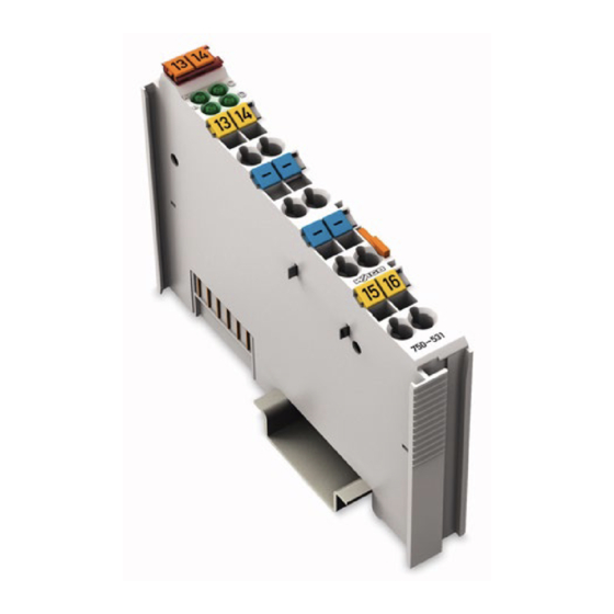
4-channel digital output module 24 vdc; 2-conductor connection; short-circuit-protected; highside switching
Hide thumbs Also See for WAGO-I/O-SYSTEM 750:
Table of Contents
  • Deutsch

    • Table of Contents
    • Table 1: Variants
    • Notes about this Documentation
    • Copyright
    • Validity of this Documentation
    • Symbols
    • Number Notation
    • Font Conventions
    • Table 2: Number Notation
    • Table 3: Font Conventions
    • Use of the WAGO-I/O-SYSTEM 750 in Compliance with Underlying Provisions
    • Personnel Qualifications
    • Subject to Changes
    • Legal Bases
    • Important Notes
    • Technical Condition of Specified Devices
    • Safety Advice (Precautions)
    • Device Description
    • View
    • Figure 1: View
    • Table 4: Legend for Figure "View
    • Figure 2: Data Contacts
    • Data Contacts/Internal Bus
    • Connectors
    • Table 5: Legend for Figure "Power Jumper Contacts
    • Figure 3: Power Jumper Contacts
    • Power Jumper Contacts/Field Supply
    • CAGE CLAMP ® Connectors
    • Figure 4: CAGE CLAMP ® Connectors
    • Table 6: Legend for Figure „CAGE CLAMP ® Connectors
    • Display Elements
    • Operating Elements
    • Figure 5: Display Elements
    • Table 7: Legend for Figure "Display Elements
    • Schematic Diagram
    • Figure 6: Schematic Diagram
    • Device Data
    • Power Supply
    • Communication
    • Outputs
    • Connection Type
    • Table 8: Technical Data - Device
    • Table 9: Technical Data - Power Supply
    • Table 10: Technical Data - Communication
    • Table 11: Technical Data - Inputs
    • Technical Data
    • Table 14: Technical Data - Data Contacts
    • Table 15: Technical Data - Climatic Environmental Conditions
    • Table 13: Technical Data - Power Jumper Contacts
    • Climatic Environmental Conditions
    • Approvals
    • Table 16: Ship Approvals
    • Standards and Guidelines
    • Mounting
    • Mounting Sequence
    • Inserting and Removing Devices
    • Inserting the I/O Module
    • Figure 7: Insert I/O Module (Example)
    • Figure 8: Snap the I/O Module into Place (Example)
    • Removing the I/O Module
    • Figure 9: Removing the I/O Module (Example)
    • Connect Devices
    • Connecting a Conductor to the CAGE CLAMP
    • Figure 10: Connecting a Conductor to a CAGE CLAMP
    • Connection Example
    • 2-Conductor Connection
    • Figure 11: Connecting Diagram 2-Conductor Connection
    • Process Image
    • Table 17: Output Bits
    • Using Interference-Free Variants of I/O Modules in Safety Related Applications
    • Important Notes
    • Figure 12: Potential Group for Safety Related Applications
    • General Structure
    • Connecting the IO Module to Safety Switching Devices or Safety Modules
    • Examples of Connection
    • Figure 13: Two-Channel Single-Pole Disconnection
    • Figure 14: Two-Channel Double-Pole Disconnection
    • Use in Hazardous Environments
    • Marking Configuration Examples
    • Marking for Europe According to ATEX and IEC-Ex
    • Figure 15: Side Marking Example for Approved I/O Modules According to ATEX and Iecex
    • Figure 16: Text Detail - Marking Example for Approved I/O Modules According to ATEX and Iecex
    • Table 18: Description of Marking Example for Approved I/O Modules According to ATEX and Iecex
    • Table 20: Description of Marking Example for Approved I/O Modules According
    • Figure 18: Text Detail - Marking Example for Approved Ex I I/O Modules According to ATEX and Iecex
    • Figure 17: Side Marking Example for Approved Ex I I/O Modules According to ATEX and Iecex
    • Table 19: Description of Marking Example for Approved Ex I I/O Modules According to ATEX and Iecex
    • Marking for America According to NEC 500
    • Figure 19: Side Marking Example for I/O Modules According to NEC 500
    • Figure 20: Text Detail - Marking Example for Approved I/O Modules According
    • Installation Regulations
    • Special Conditions for Safe Use (ATEX Certificate TÜV 07 ATEX 554086 X)
    • Special Conditions for Safe Use (ATEX Certificate TÜV 12 ATEX 106032 X)
    • Special Conditions for Safe Use (IEC-Ex Certificate TUN 09.0001
    • Special Conditions for Safe Use (IEC-Ex Certificate Iecex TUN 12.0039 X)
    • Special Conditions for Safe Use According to ANSI/ISA

Advertisement

Quick Links

Pos : 2 /D okumentati on allgemein/Ei nband/Ei nband H andbuch - Dec kbl att ohne Variantenfel d (Standar d) @ 9\mod_1285229289866_0.doc x @ 64941 @ @ 1
Manual
WAGO-I/O-SYSTEM 750
4DO 24V DC 0.5A/ 2-conductor
750-531(/xxx-xxx)
4-Channel Digital Output Module 24 VDC; 2-
Conductor Connection; Short-circuit-protected; High-
side Switching
Version 1.3.0
Pos : 3 /Alle Serien (Allgemeine M odul e)/Hinweise z ur Dokumentation/Impres sum für Standardhandbüc her - allg. Angaben, Ansc hriften, Tel efonnummer n und E-Mail-Adres sen @ 3\mod_1219151118203_21.doc x @ 21060 @ @ 1

Advertisement

Chapters

Table of Contents
loading

Summary of Contents for WAGO WAGO-I/O-SYSTEM 750

  • Page 1 Pos : 2 /D okumentati on allgemein/Ei nband/Ei nband H andbuch - Dec kbl att ohne Variantenfel d (Standar d) @ 9\mod_1285229289866_0.doc x @ 64941 @ @ 1 Manual WAGO-I/O-SYSTEM 750 4DO 24V DC 0.5A/ 2-conductor 750-531(/xxx-xxx) 4-Channel Digital Output Module 24 VDC; 2- Conductor Connection;...
  • Page 2 WAGO-I/O-SYSTEM 750 750-531 4DO 24V DC 0.5A/ 2-conductor © 2015 by WAGO Kontakttechnik GmbH & Co. KG All rights reserved. WAGO Kontakttechnik GmbH & Co. KG Hansastraße 27 D-32423 Minden Phone: +49 (0) 571/8 87 – 0 Fax: +49 (0) 571/8 87 – 1 69 E-Mail: info@wago.com...
  • Page 3: Table Of Contents

    2.1.1 Subject to Changes ................9 2.1.2 Personnel Qualifications ............... 9 2.1.3 Use of the WAGO-I/O-SYSTEM 750 in Compliance with Underlying Provisions ..................... 9 2.1.4 Technical Condition of Specified Devices ......... 10 Safety Advice (Precautions) ..............11 Device Description ..................13 View ......................
  • Page 4 Table of Contents WAGO-I/O-SYSTEM 750 750-531 4DO 24V DC 0.5A/ 2-conductor Important Notes ..................34 Connecting the IO Module to Safety Switching Devices or Safety Modules ....................35 7.2.1 General Structure ................35 7.2.2 Examples of Connection..............36 Use in Hazardous Environments .............. 38 Marking Configuration Examples ............
  • Page 5: Notes About This Documentation

    Pos : 10 /Serie 750 ( WAGO-I/O-SYST EM)/Hi nweis e z ur D okumentati on/Gültigkeits bereic h/Gültig keits ber eich Dokumentation Bus kl emme 750- xxxx, Standar dversi on und aufgelistete Varianten @ 14\mod_1358944038682_21.doc x @ 109354 @ @ 1...
  • Page 6: Symbols

    Notes about this Documentation WAGO-I/O-SYSTEM 750 750-531 4DO 24V DC 0.5A/ 2-conductor Pos : 14.3 /All e Seri en ( Allgemei ne Module)/Ü bers chriften für alle Serien/Hinweis e z ur Dokumentation/Symbol e - Ü bersc hrift 2 @ 13\mod_1351068042408_21.doc x @ 105270 @ 2 @ 1 Symbols Pos : 14.4.1 /All e Serien ( Allgemei ne Module)/Wic htige Erläuterungen/Sicherheits- und sons tige Hinweis e/Gefahr/Gefahr: _War nung vor Personenschäden allgemei n_ - Erl äuter ung @ 13\mod_1343309450020_21.doc x @ 101029 @ @ 1...
  • Page 7 WAGO-I/O-SYSTEM 750 Notes about this Documentation 750-531 4DO 24V DC 0.5A/ 2-conductor Additional Information: Refers to additional information which is not an integral part of this documentation (e.g., the Internet). Pos : 14.5 /Dokumentation allgemei n/Glieder ungs elemente/---Seitenwechs el--- @ 3\mod_1221108045078_0.doc x @ 21810 @ @ 1 Manual Version 1.3.0...
  • Page 8: Number Notation

    Font Conventions Table 3: Font Conventions Font Type Indicates italic Names of paths and data files are marked in italic-type. e.g.: C:\Program Files\WAGO Software Menu Menu items are marked in bold letters. e.g.: Save > A greater-than sign between two names means the selection of a menu item from a menu.
  • Page 9: Important Notes

    PLC programming. Pos : 17.5 /Serie 750 (WAGO-I/O-SYST EM)/Wic htige Erläuterungen/Bes timmungsgemäß e Verwendung Bes ti mmungsgemäße Verwendung 750-xxxx - Ü berschrift 3 und Inhal t @ 3\mod_1224064151234_21.doc x @ 24070 @ 3 @ 1 2.1.3...
  • Page 10: Technical Condition Of Specified Devices

    WAGO-I/O-SYSTEM 750 750-531 4DO 24V DC 0.5A/ 2-conductor Appropriate housing (per 94/9/EG) is required when operating the WAGO-I/O- SYSTEM 750 in hazardous environments. Please note that a prototype test certificate must be obtained that confirms the correct installation of the system in a housing or switch cabinet.
  • Page 11: Safety Advice (Precautions)

    Pos : 17.10.2 /Serie 750 ( WAGO-I/O- SYST EM)/Wic htig e Erl äuter ung en/Sic her hei ts- und s onstige Hi nweise/Gefahr/Gefahr: Ei nbau 0750- xxxx nur i n Gehäus en, Sc hränken oder el ektrisc hen Betriebsräumen! @ 6\mod_1260180556692_21.doc...
  • Page 12 Important Notes WAGO-I/O-SYSTEM 750 750-531 4DO 24V DC 0.5A/ 2-conductor Do not use any contact spray! Do not use any contact spray. The spray may impair contact area functionality in connection with contamination. Pos : 17.11.5 /Alle Serien (Allgemeine D okumente) (Allgemeine M odul e)/Wichtige Erläuter ungen/Sic herheits hinweise/Ac htung/Ac htung: Verpol ung ver mei den! @ 6\mod_1260184045744_21.doc x @ 46767 @ @ 1...
  • Page 13: Device Description

    Pos : 20.10 /Serie 750 ( WAGO-I/O-SYST EM)/Wichtig e Erl äuter ung en/Sic her hei ts- und s onstige Hinweise/Ac htungAc htung: D O Ü berlasts chutz - Ei npeis eklemme mit Sic her ung @ 3\mod_1233814881117_21.doc...
  • Page 14 Pos : 20.16 /Serie 750 ( WAGO-I/O-SYST EM)/Wichtig e Erl äuter ung en/Sic her hei ts- und s onstige Hinweise/War nungWarnung: Ei ns atz Variante /xxx- 8xx in sicherheitsg erichteten Anwendung en @ 5\mod_1246882860453_21.doc x @ 36680 @ @ 1...
  • Page 15: View

    Pos : 23 /Serie 750 ( WAGO-I/O-SYST EM)/Ger ätebesc hrei bung/Ansic ht/Digitalausgangs kl emmen/Ansic ht 750-0531 - Abb. @ 10\mod_1298370507089_21.doc x @ 69791 @ @ 1 Figure 1: View Pos : 24 /Serie 750 ( WAGO-I/O-SYST EM)/Ger ätebesc hrei bung/Ansic ht/Ansic ht C ageCl amp® _Leg ende mit LED s @ 15\mod_1370867188922_21.doc x @ 122225 @ @ 1 Table 4: Legend for Figure “View”...
  • Page 16: Connectors

    Pos : 28.3 /Serie 750 (WAGO-I/O-SYST EM)/Wic htige Erläuterungen/Sicherheits- und sonstig e Hinweis e/Achtung/Achtung: ESD - Auf g ute Erdung der U mgebung ac hten! @ 7\mod_1266318538667_21.doc x @ 50708 @ @ 1 Ensure that the environment is well grounded! The devices are equipped with electronic components that may be destroyed by electrostatic discharge.
  • Page 17: Power Jumper Contacts/Field Supply

    Pos : 31.3 /Serie 750 (WAGO-I/O-SYST EM)/Ger ätebesc hrei bung/Ansc hl üsse/Leistungs kontakte 2 LK (Mess er/Leis tungs kontakte 2 LK (Messer /Feder) - Abbil dung, einfac he Breite - Standard @ 15\mod_1367500700037_21.doc x @ 118396 @ @ 1 Figure 3: Power Jumper Contacts Pos : 31.4 /Serie 750 (WAGO-I/O-SYST EM)/Ger ätebesc hrei bung/Ansc hl üsse/Leistungs kontakte 2 LK (Mess er/Leis tungs kontakte 2 LK (Messer /Feder) - Legende @ 15\mod_1371721352500_21.doc x @ 123710 @ @ 1...
  • Page 18 Device Description WAGO-I/O-SYSTEM 750 750-531 4DO 24V DC 0.5A/ 2-conductor Use supply modules for ground (earth)! The I/O module has no power jumper contacts for receiving and transmitting the earth potential. Use a supply module when an earth potential is needed for the subsequent I/O modules.
  • Page 19: Cage Clamp ® Connectors

    CAGE CLAMP Connectors Pos : 34 /Serie 750 ( WAGO-I/O-SYST EM)/Ger ätebesc hrei bung/Ansc hl üss e/Digital ausg angs kl emmen/Anschl üss e 750- 0531, 0532 CC @ 10\mod_1298374574196_21.doc x @ 69891 @ @ 1 ® Figure 4: CAGE CLAMP Connectors ®...
  • Page 20: Display Elements

    Operating Elements Pos : 39 /Serie 750 ( WAGO-I/O-SYST EM)/Ger ätebesc hrei bung/Bedienel emente/Bedi enel emente Bus kl emme 750- xxxx nic ht vor handen @ 4\mod_1236322031125_21.doc x @ 28063 @ @ 1 The I/O module 750-531 has no operating elements.
  • Page 21: Schematic Diagram

    Pos : 41 /All e Seri en (Allgemei ne Module)/Ü berschriften für alle Serien/Gerätebesc hreibung/Sc hematisches Sc haltbil d - Ü bersc hrift 2 @ 4\mod_1240984441312_21.doc x @ 31967 @ 2 @ 1 Schematic Diagram Pos : 42 /Serie 750 ( WAGO-I/O-SYST EM)/Ger ätebesc hrei bung/Schematisc he Sc haltbil der/Digitalausgangs klemmen/Schematisc hes Sc haltbil d 750-0531 @ 10\mod_1298371105956_21.doc x @ 69851 @ @ 1 Figure 6: Schematic Diagram Pos : 43 /D okumentation allgemei n/Glieder ungs elemente/---Seitenwechs el--- @ 3\mod_1221108045078_0.doc x @ 21810 @ @ 1...
  • Page 22: Technical Data

    Connection Type Pos : 46.2 /Serie 750 (WAGO-I/O-SYST EM)/Ger ätebesc hrei bung/T echnisc he Daten/T ec hnische D aten Verdr ahtungs ebene CC - 0,08 bis 2,5mm2 @ 17\mod_1380121238809_21.doc x @ 132780 @ @ 1 Table 12: Technical Data – Field Wiring ®...
  • Page 23: Climatic Environmental Conditions

    Pos : 47 /Serie 750 ( WAGO-I/O-SYST EM)/Ger ätebesc hrei bung/T echnisc he Daten/Kli matische U mweltbeding ung en/Technisc he Daten Klimat. U mweltbed. ohne erw. T emp. 0...55°C /-25...+85°C @ 5\mod_1247657968368_21.doc x @ 37603 @ 3 @ 1 3.6.6...
  • Page 24: Approvals

    Pos : 51 /Serie 750 ( WAGO-I/O-SYST EM)/Ger ätebesc hrei bung/Z ulass ungen/Allgemei n/Z ulass ungen Bus kl emme 750- xxxx Allgemein, Standardversi on und all e Vari anten - Einl eitung @ 3\mod_1233911570312_21.doc x @ 27390 @ @ 1...
  • Page 25: Table 16: Ship Approvals

    750-531 4DO 24V DC 0.5A/ 2-conductor Pos : 58 /Serie 750 ( WAGO-I/O-SYST EM)/Ger ätebesc hrei bung/Z ulass ungen/Schiff/Z ulas sungen Bus klemme 750- xxxx Sc hiff, Standardversion und aufgelistete Vari anten - Einl eitung @ 16\mod_1376313495745_21.doc x @ 128461 @ @ 1...
  • Page 26: Standards And Guidelines

    Standards and Guidelines Pos : 63 /Serie 750 ( WAGO-I/O-SYST EM)/Ger ätebesc hrei bung/N ormen und Ric htlini en/EM V-Nor men Bus kl emme 750- xxxx, ohne Variantenang abe - Einl eitung @ 4\mod_1242803944015_21.doc x @ 33642 @ @ 1...
  • Page 27: Mounting

    I/O modules with fewer power contacts. Pos : 70.2 /Serie 750 (WAGO-I/O-SYST EM)/Wic htige Erläuterungen/Sicherheits- und sonstig e Hinweis e/Vorsic ht/Vorsicht: Verl etz ungsgefahr durc h s charfkantige M ess er kontakte! @ 6\mod_1256193279401_21.doc x @ 43414 @ @ 1 Risk of injury due to sharp-edged blade contacts! The blade contacts are sharp-edged.
  • Page 28: Inserting And Removing Devices

    WAGO-I/O-SYSTEM 750 750-531 4DO 24V DC 0.5A/ 2-conductor Pos : 70.6 /Serie 750 (WAGO-I/O-SYST EM)/M ontieren/D emontieren/Geräte einfüg en und entfer nen - Ü berschrift 2 @ 3\mod_1231768483250_21.doc x @ 25950 @ 2 @ 1 Inserting and Removing Devices Pos : 70.7 /All e Seri en ( Allgemei ne Module)/Wic htige Erläuterungen/Sicherheits- und sons tige Hi nweis e/Ac htung/Achtung: Arbeiten an Ger äten nur s pannungsfr ei durc hführ en! @ 6\mod_1256193963573_21.doc x @ 43426 @ @ 1 Perform work on devices only if they are de-energized! Working on energized devices can damage them.
  • Page 29: Removing The I/O Module

    WAGO-I/O-SYSTEM 750 Mounting 750-531 4DO 24V DC 0.5A/ 2-conductor Pos : 70.10 /Serie 750 ( WAGO-I/O-SYST EM)/Monti eren/D emonti eren/Bus kl emme entfer nen @ 4\mod_1239169375203_21.doc x @ 30334 @ 3 @ 1 4.2.2 Removing the I/O Module Remove the I/O module from the assembly by pulling the release tab.
  • Page 30: Connect Devices

    Connect Devices Pos : 73 /Serie 750 ( WAGO-I/O-SYST EM)/Ans chli eßen/Leiter an C AGE C LAM P ans chli eßen ( allgemei n) - Übersc hrift 2 und Text @ 3\mod_1225448660171_21.doc x @ 24928 @ 2 @ 1 ®...
  • Page 31: Connection Example

    Pos : 75 /All e Seri en (Allgemei ne Module)/Ü berschriften für alle Serien/Ansc hließ en/Ans chl uss beis piel - Übersc hrift 2 @ 4\mod_1242621672468_21.doc x @ 33293 @ 2 @ 1 Connection Example Pos : 76 /Serie 750 ( WAGO-I/O-SYST EM)/Ans chli eßen/Anschl uss beispi ele/Digitalausgangs klemmen/Ansc hl ussbeis piel e 750-0531, 532 @ 10\mod_1298558411107_21.doc x @ 70206 @ 3 @ 1 5.2.1...
  • Page 32: Process Image

    Process Image Pos : 79 /Serie 750 ( WAGO-I/O-SYST EM)/Proz ess abbild Kl emmenbus /Hinweis: Prozes sabbildmapping abhängig von FBK/PFC, ohne Status-/C ontr olbyte @ 6\mod_1256126797251_21.doc x @ 43340 @ @ 1 Mapping of process data in the process image of fieldbus systems The representation of the process data of some I/O modules or their variants in the process image depends on the fieldbus coupler/controller used.
  • Page 33: Using Interference-Free Variants Of I/O Modules In Safety Related Applications

    750-531 4DO 24V DC 0.5A/ 2-conductor Pos : 82.1 /Serie 750 (WAGO-I/O-SYST EM)/Eins atz in sicherheitsg erichteten Anwendung en/Ei nleitung - r üc kwir kungsfr eie Varianten @ 6\mod_1258973563064_21.doc x @ 44681 @ 1 @ 1 Using Interference-Free Variants of I/O Modules in Safety Related Applications The variant 750-531/xxx-8xx of the I/O module 750-531 (designation “...
  • Page 34: Important Notes

    750-531 4DO 24V DC 0.5A/ 2-conductor Pos : 82.4 /Serie 750 (WAGO-I/O-SYST EM)/Eins atz in sicherheitsg erichteten Anwendung en/Hi nweise zum Ei nsatz i n Sicherheits anwendungen @ 6\mod_1258974811438_21.doc x @ 44688 @ 2 @ 1 Eins atz der rüc kwir kungsfrei en Digital ausg angs kl emme in Sic her heitsanwendungen...
  • Page 35: Connecting The Io Module To Safety Switching Devices Or Safety Modules

    750-531 4DO 24V DC 0.5A/ 2-conductor Pos : 82.6 /Serie 750 (WAGO-I/O-SYST EM)/Eins atz in sicherheitsg erichteten Anwendung en/Allgemeiner Aufbau ei ner Potenti algruppe - r üc kwir kungsfr eie Vari anten @ 6\mod_1258973074755_21.doc x @ 44664 @ 23 @ 1...
  • Page 36: Examples Of Connection

    750-531 4DO 24V DC 0.5A/ 2-conductor Pos : 84 /Serie 750 ( WAGO-I/O-SYST EM)/Eins atz in sicherheitsg erichteten Anwendung en/Ansc hluss beispi ele/Ansc hlussbeis piel 2/4-Kanal-Digital ausg angs kl emmen i n Sicherheits anwendungen @ 6\mod_1259219930757_21.doc x @ 45290 @ 3 @ 1 Eins atz der rüc kwir kungsfrei en Digital ausg angs kl emme in Sic her heitsanwendungen...
  • Page 37: Figure 14: Two-Channel Double-Pole Disconnection

    WAGO-I/O-SYSTEM 750 Using Interference-Free Variants of I/O Modules in Safety Related Applications 750-531 4DO 24V DC 0.5A/ 2-conductor Figure 14: Two-channel Double-pole Disconnection Pos : 85 /D okumentation allgemei n/Glieder ungs elemente/---Seitenwechs el--- @ 3\mod_1221108045078_0.doc x @ 21810 @ @ 1 Manual Version 1.3.0...
  • Page 38: Use In Hazardous Environments

    Use in Hazardous Environments Pos : 86.2 /Serie 750 (WAGO-I/O-SYST EM)/Eins atz in Ex- Ber eichen/Ei ns atz ber eich Serie 750 @ 3\mod_1234272230203_21.doc x @ 27500 @ @ 1 The WAGO-I/O-SYSTEM 750 (electrical equipment) is designed for use in Zone 2 hazardous areas.
  • Page 39: Marking Configuration Examples

    Marking for Europe According to ATEX and IEC-Ex Pos : 86.6 /Serie 750 (WAGO-I/O-SYST EM)/Eins atz in Ex- Ber eichen/Beis piel bedruc kung der ATEX- und IEC- Ex-zug elass enen Bus klemmen gemäß C ENELEC und IEC_2013 @ 14\mod_1360569228625_21.doc x @ 111294 @ @ 1 Figure 15: Side Marking Example for Approved I/O Modules According to ATEX and IECEx Figure 16: Text Detail –...
  • Page 40: Table 18: Description Of Marking Example For Approved I/O Modules According To Atex And Iecex

    Use in Hazardous Environments WAGO-I/O-SYSTEM 750 750-531 4DO 24V DC 0.5A/ 2-conductor Table 18: Description of Marking Example for Approved I/O Modules According to ATEX and IECEx Printing on Text Description TÜV 07 ATEX 554086 X Approving authority and certificate numbers IECEx TUN 09.0001 X...
  • Page 41: Figure 17: Side Marking Example For Approved Ex I I/O Modules According To Atex And Iecex

    750-531 4DO 24V DC 0.5A/ 2-conductor Pos : 86.8 /Serie 750 (WAGO-I/O-SYST EM)/Eins atz in Ex- Ber eichen/Beis piel bedruc kung der Ex-i- und IEC-Ex-i-zug elas senen Bus klemmen gemäß C ENELEC und IEC _2013 @ 14\mod_1360569320118_21.doc x @ 111298 @ @ 1 Figure 17: Side Marking Example for Approved Ex i I/O Modules According to ATEX and IECEx.
  • Page 42 Use in Hazardous Environments WAGO-I/O-SYSTEM 750 750-531 4DO 24V DC 0.5A/ 2-conductor Table 19: Description of Marking Example for Approved Ex i I/O Modules According to ATEX and IECEx Inscription Text Description TÜV 07 ATEX 554086 X Approving authority and certificate numbers IECEx TUN 09.0001X...
  • Page 43: Table 19: Description Of Marking Example For Approved Ex I I/O Modules According To Atex And Iecex

    WAGO-I/O-SYSTEM 750 Use in Hazardous Environments 750-531 4DO 24V DC 0.5A/ 2-conductor Table 19: Description of Marking Example for Approved Ex i I/O Modules According to ATEX and IECEx Gases Equipment group: All except mining 3(1)G Category 3 (Zone 2) equipment containing a safety...
  • Page 44: Marking For America According To Nec 500

    750-531 4DO 24V DC 0.5A/ 2-conductor Pos : 86.10 /Serie 750 ( WAGO-I/O-SYST EM)/Ei ns atz i n Ex-Bereic hen/Kennz eichnung für Ameri ka gemäß N EC 500 - Übersc hrift 3 @ 3\mod_1224158423187_21.doc x @ 24188 @ 3 @ 1 8.1.2...
  • Page 45: Installation Regulations

    WAGO-I/O-SYSTEM 750 Use in Hazardous Environments 750-531 4DO 24V DC 0.5A/ 2-conductor Pos : 86.13 /Alle Serien (Allgemeine M odul e)/Ei ns atz i n Ex-Bereic hen/Errichtungsbes timmungen - Ü bersc hrift 2 @ 3\mod_1232453624234_21.doc x @ 26370 @ 2 @ 1 Installation Regulations Pos : 86.14 /Alle Serien (Allgemeine M odul e)/Ei ns atz i n Ex-Bereic hen/Errichtungsbes timmungen Ei nleitung_2013 @ 14\mod_1360582328318_21.doc x @ 111371 @ @ 1...
  • Page 46: Special Conditions For Safe Use (Atex Certificate Tüv 07 Atex 554086 X)

    Pos : 86.16 /Serie 750 ( WAGO-I/O-SYST EM)/Ei ns atz i n Ex-Bereic hen/Besonder e Beding ung en für den sic her en Ex- Betrieb gem. AT EX-Z ertifi kat TÜV 07 ATEX 554086_X_2013_2 @ 15\mod_1368620071975_21.doc...
  • Page 47: Special Conditions For Safe Use (Atex Certificate Tüv 12 Atex 106032 X)

    Pos : 86.18 /Serie 750 ( WAGO-I/O-SYST EM)/Ei ns atz i n Ex-Bereic hen/Besonder e Beding ung en für den sic her en Ex- Betrieb gem. AT EX-Z ertifi kat TÜV 12 ATEX 106032x_2013_2 @ 15\mod_1368620479454_21.doc...
  • Page 48: Special Conditions For Safe Use (Iec-Ex Certificate Tun 09.0001

    Pos : 86.20 /Serie 750 ( WAGO-I/O-SYST EM)/Ei ns atz i n Ex-Bereic hen/Besonder e Beding ung en für den sic her en Ex- Betrieb gem. IEC-Ex-Z ertifi kat TUN 09.0001 X_2013_2 @ 15\mod_1368620660911_21.doc...
  • Page 49: Special Conditions For Safe Use (Iec-Ex Certificate Iecex Tun 12.0039 X)

    Pos : 86.22 /Serie 750 ( WAGO-I/O-SYST EM)/Ei ns atz i n Ex-Bereic hen/Besonder e Beding ung en für den sic her en Ex- Betrieb gem. IEC-Ex-Z ertifi kat TUN 12.0039 X_2013_2 @ 15\mod_1368620821493_21.doc...
  • Page 50: Special Conditions For Safe Use According To Ansi/Isa

    WAGO-I/O-SYSTEM 750 750-531 4DO 24V DC 0.5A/ 2-conductor Pos : 86.24 /Serie 750 ( WAGO-I/O-SYST EM)/Ei ns atz i n Ex-Bereic hen/Errichtungsbesti mmung en AN SI ISA 12.12.01_2013_2 @ 15\mod_1368620942842_21.doc x @ 119794 @ 3 @ 1 8.2.5 Special Conditions for Safe Use According to ANSI/ISA 12.12.01...
  • Page 51: List Of Figures

    WAGO-I/O-SYSTEM 750 List of Figures 750-531 4DO 24V DC 0.5A/ 2-conductor Pos : 88 /D okumentation allgemei n/Verz eic hniss e/Abbil dungs verz eic hnis - Übersc hrift oG und Verz eichnis @ 3\mod_1219222916765_21.doc x @ 21080 @ @ 1 List of Figures Figure 1: View .......................
  • Page 52: List Of Tables

    List of Tables WAGO-I/O-SYSTEM 750 750-531 4DO 24V DC 0.5A/ 2-conductor Pos : 90 /D okumentation allgemei n/Verz eic hniss e/Tabell enverz eichnis - Übersc hrift oG und Verz eichnis @ 3\mod_1219222958703_21.doc x @ 21084 @ @ 1 List of Tables Table 1: Variants .....................
  • Page 53 WAGO-I/O-SYSTEM 750 750-531 4DO 24V DC 0.5A/ 2-conductor Pos : 92 /D okumentation allgemei n/Einband/Einband H andbuc h - Leers eite für durc h 2 teilbar e Seitenzahl (Standar ddr uc k) @ 3\mod_1219230851078_0.doc x @ 21123 @ @ 1 Manual Version 1.3.0...
  • Page 54 Pos : 93 /D okumentation allgemei n/Einband/Einband H andbuc h - R üc kseite @ 9\mod_1285229376516_21.doc x @ 64944 @ @ 1 WAGO Kontakttechnik GmbH & Co. KG Postfach 2880 • D-32385 Minden Hansastraße 27 • D-32423 Minden Phone: +49/5 71/8 87 – 0 Fax: +49/5 71/8 87 –...

This manual is also suitable for:

750-531750-531/000-800

Table of Contents