
Related Manuals for WAGO 750-344


Summary of Contents for WAGO 750-344
- Page 1 Modular I/O system INTERBUS 750-344, 750-345 Manual Technical Description, Installation and Configuration Version 1.0.0...
- Page 2 • General Copyright 2002 by WAGO Kontakttechnik GmbH All rights reserved. WAGO Kontakttechnik GmbH Hansastraße 27 D-32423 Minden Phone: +49 (0) 571/8 87 – 0 Fax: +49 (0) 571/8 87 – 1 69 E-mail: info@wago.com Web: http://www.wago.com Technical Support Phone: +49 (0) 571/8 87 –...
-
Page 3: Table Of Contents
Grounding .................... 40 Shielding (Screening) ................43 2.10 Assembly Guidelines/Standards ............44 3 Fieldbus Couplers ..................45 Feldbus Coupler 750-344 / -345 ............45 4 I/O Modules ....................76 5 INTERBUS ....................77 Overview....................77 Interface Modules ................80 Configuration Software................ 80... - Page 4 • Table of Contents WAGO-I/O-SYSTEM 750 INTERBUS...
-
Page 5: Important Notes
Co. KG, Minden, Germany. Non-observance will involve the right to assert damage claims. WAGO Kontakttechnik GmbH & Co. KG reserves the right to provide for any alterations or modifications that serve to increase the efficiency of technical progress. WAGO Kontakttechnik GmbH & Co. KG owns all rights arising from the granting of patents or from the legal protection of utility patents. - Page 6 Legal Bases All responsible persons have to familiarize themselves with the underlying legal standards to be applied. WAGO Kontakttechnik GmbH & Co. KG does not assume any liability whatsoever resulting from improper handling and damage incurred to both WAGO´s own and third-party products by disregarding detailed information in this Manual.
-
Page 7: Standards And Guidelines For Operating The 750 Series
(emissions of interference) in compliance with EN 61000-6-3. You will find the detailed information in section "WAGO-I/O-SYSTEM 750" "System Description" "Technical Data". Please observe the safety precautions against electrostatic discharge in accordance with DIN EN 61340-5-1/-3. -
Page 8: Symbols
Observe the precautionary measure for handling components at risk of electrostatic discharge. Note Make important notes that are to be complied with so that a trouble-free and efficient device operation can be guaranteed. Additional Information References to additional literature, manuals, data sheets and internet pages. WAGO-I/O-SYSTEM 750 INTERBUS... -
Page 9: Safety Information
Danger The WAGO-I/O-SYSTEM 750 and its components are an open system. It must only be assembled in housings, cabinets or in electrical operation rooms. Access is only permitted via a key or tool to authorized qualified personnel. -
Page 10: Font Conventions
Only for use in LAN, not for connection to telecommunication circuits. 1.5 Font Conventions Names of paths and data files are marked in italic-type. italic e.g.: C:\Programs\WAGO-IO-CHECK Menu items are marked in italic-type, bold letters. italic e.g.: Save A backslash between two names characterizes the selection of a menu point from a menu. -
Page 11: Scope Of Validity
Important Notes • 11 Scope of Validity 1.7 Scope of Validity This manual outlines all the components for the fieldbus-independent WAGO-I/O-SYSTEM 750 with an INTERBUS-ECO fieldbus coupler. Item no. Description 750-344 INTERBUS-ECO Fieldbus coupler, 500 kBaud 750-345 INTERBUS-ECO Fieldbus coupler, 2 MBaud 1.8 Abbreviations... -
Page 12: The Wago-I/O-System 750
The WAGO-I/O-SYSTEM 750 has a clear port level with LEDs for status indication, insertable mini WSB markers and pullout group marker carriers. The 3-wire technology supplemented by a ground wire connection allows for direct sensor/actuator wiring. -
Page 13: Technical Data
25 ppm relative humidity < 75% S 10 ppm Special conditions Ensure that additional measures for components are taken, which are used in an environment involving: – dust, caustic vapors or gases – ionization radiation WAGO-I/O-SYSTEM 750 INTERBUS... - Page 14 14 • The WAGO-I/O-SYSTEM 750 Technical Data Safe electrical isolation Air and creepage distance acc. to IEC 60664-1 Degree of pollution acc. To IEC 61131-2 Degree of protection Degree of protection IP 20 Electromagnetic compatibility Immunity to interference for industrial areas acc. to EN 61000-6-2 (2001)
- Page 15 IEC 60068-2-32 free fall (module in original packing) *) QP: Quasi Peak Note If the technical data of components differ from the values described here, the technical data shown in the manuals of the respective components shall be valid. WAGO-I/O-SYSTEM 750 INTERBUS...
- Page 16 16 • The WAGO-I/O-SYSTEM 750 Technical Data For Products of the WAGO-I/O-SYSTEM 750 with ship specific approvals supplementary guidelines are valid: Electromagnetic compatibility Immunity to interference acc. to Germanischer Lloyd (2003) Test specification Test values Strength Evaluation class criteria IEC 61000-4-2 ESD...
- Page 17 In Germany, the Federal Office for Post and Telecommunications and its branch offices issues the permit. It is possible to use other field bus couplers/controllers under certain boundary conditions. Please contact WAGO Kontakttechnik GmbH & Co. KG. Maximum power dissipation of the components Bus modules 0.8 W / bus terminal (total power dissipation,...
- Page 18 18 • The WAGO-I/O-SYSTEM 750 Technical Data Dimensions 01 02 24V 0V Side view Dimensions in mm Fig. 2-2: Dimensions g01xx05e Note The illustration shows a standard coupler. For detailed dimensions, please refer to the technical data of the respective coupler/controller.
-
Page 19: Manufacturing Number
The manufacturing number consists of the production week and year, the software version (if available), the hardware version of the component, the firmware loader (if available) and further internal information for WAGO Kontakttechnik GmbH & Co. KG. WAGO-I/O-SYSTEM 750 INTERBUS... -
Page 20: Component Update
20 • The WAGO-I/O-SYSTEM 750 Component Update 2.4 Component Update For the case of an Update of one component, the lateral marking on each component contains a prepared matrix. This matrix makes columns available for altogether three updates to the entry of the current update data, like production order number (NO;... -
Page 21: Mechanical Setup
Attention In the case of vertical assembly, an end stop has to be mounted as an additional safeguard against slipping. WAGO item 249-116 End stop for DIN 35 rail, 6 mm wide WAGO item 249-117 End stop for DIN 35 rail, 10 mm wide 2.6.2 Total Expansion... - Page 22 WAGO Kontakttechnik GmbH & Co. KG supplies standardized carrier rails that are optimal for use with the I/O system. If other carrier rails are used, then a technical inspection and approval of the rail by WAGO Kontakttechnik GmbH & Co. KG should take place.
- Page 23 Spacing • 23 WAGO DIN Rail 2.6.3.2 WAGO DIN Rail WAGO carrier rails meet the electrical and mechanical requirements. Item Number Description 210-113 /-112 35 x 7.5; 1 mm; steel yellow chromated; slotted/unslotted 210-114 /-197 35 x 15; 1.5 mm; steel yellow chromated; slotted/unslotted 210-118 35 x 15;...
- Page 24 24 • The WAGO-I/O-SYSTEM 750 Mechanical Setup 2.6.5 Plugging and Removal of the Components Warning Before work is done on the components, the voltage supply must be turned off. In order to safeguard the coupler/controller from jamming, it should be fixed onto the carrier rail with the locking disc To do so, push on the upper groove of the locking disc using a screwdriver.
- Page 25 Assembly Sequence • 25 WAGO DIN Rail 2.6.6 Assembly Sequence All system components can be snapped directly on a carrier rail in accordance with the European standard EN 50022 (DIN 35). The reliable positioning and connection is made using a tongue and groove system.
- Page 26 26 • The WAGO-I/O-SYSTEM 750 Mechanical Setup 2.6.7 Internal Bus/Data Contacts Communication between the coupler/controller and the bus modules as well as the system supply of the bus modules is carried out via the internal bus. It is comprised of 6 data contacts, which are available as self-cleaning gold spring contacts.
- Page 27 Fig. 2-8: Example for the arrangement of power contacts g0xxx05e Recommendation With the WAGO ProServe® Software smartDESIGNER, the structure of a field bus node can be configured. The configuration can be tested via the integrated accuracy check. WAGO-I/O-SYSTEM 750...
- Page 28 More than one conductor per connection is not permissible. If several conductors have to be made at one connection point, then they should be made away from the connection point using WAGO Terminal Blocks. The terminal blocks may be jumpered together and a single wire brought back to the I/O module connection point.
-
Page 29: Power Supply
Isolation • 29 WAGO DIN Rail 2.7 Power Supply 2.7.1 Isolation Within the field bus node, there are three electrically isolated potentials. Operational voltage for the field bus interface. Electronics of the couplers/controllers and the bus modules (internal bus). - Page 30 2.7.2 System Supply 2.7.2.1 Connection The WAGO-I/O-SYSTEM 750 requires a 24 V direct current system supply (-15 % or +20 %). The power supply is provided via the coupler/controller and, if necessary, in addition via the internal system supply modules (750-613).
- Page 31 Attention If the sum of the internal current consumption exceeds the residual current for bus modules, then an internal system supply module (750-613) must be placed before the module where the permissible residual current was exceeded. WAGO-I/O-SYSTEM 750 INTERBUS...
- Page 32 (750-613), e.g. in the middle of the node, should be added. Recommendation With the WAGO ProServe® Software smartDESIGNER, the assembly of a field bus node can be configured. The configuration can be tested via the integrated accuracy check.
- Page 33 By inserting an additional power supply module, the field supply via the power contacts is disrupted. From there a new power supply occurs which may also contain a new voltage potential. WAGO-I/O-SYSTEM 750 INTERBUS...
- Page 34 34 • The WAGO-I/O-SYSTEM 750 Power Supply Attention Some bus modules have no or very few power contacts (depending on the I/O function). Due to this, the passing through of the relevant potential is disrupted. If a field supply is required for subsequent bus modules, then a power supply module must be used.
- Page 35 Lifting the cover to the side opens the fuse carrier. Fig. 2-16: Opening the fuse carrier p0xxx03x Fig. 2-17: Change fuse p0xxx04x After changing the fuse, the fuse carrier is pushed back into its original position. WAGO-I/O-SYSTEM 750 INTERBUS...
- Page 36 36 • The WAGO-I/O-SYSTEM 750 Power Supply Alternatively, fusing can be done externally. The fuse modules of the WAGO series 281 and 282 are suitable for this purpose. Fig. 2-18: Fuse modules for automotive fuses, series 282 pf66800x Abb. 2-19: Fuse modules for automotive fuses, series 2006 p0xxx13x Fig.
- Page 37 • 37 Fusing 2.7.4 Supplementary Power Supply Regulations The WAGO-I/O-SYSTEM 750 can also be used in shipbuilding or offshore and onshore areas of work (e. g. working platforms, loading plants). This is demonstrated by complying with the standards of influential classification companies such as Germanischer Lloyd and Lloyds Register.
- Page 38 38 • The WAGO-I/O-SYSTEM 750 Power Supply 2.7.5 Supply Example Attention The system supply and the field supply should be separated in order to ensure bus operation in the event of a short-circuit on the actuator side. 750-400 750-410 750-401...
- Page 39 • 39 Fusing 2.7.6 Power Supply Unit The WAGO-I/O-SYSTEM 750 requires a 24 V direct current system supply with a maximum deviation of -15 % or +20 %. Recommendation A stable network supply cannot be taken for granted always and everywhere.
-
Page 40: Grounding
The optimal insulated setup is a metallic assembly plate with grounding connection with an electrical conductive link with the carrier rail. The separate grounding of the carrier rail can be easily set up with the aid of the WAGO ground wire terminals. Item No. Description... - Page 41 Attention Care must be taken to ensure the direct electrical connection between the carrier rail contact and the carrier rail. The carrier rail must be grounded. For information on carrier rail properties, please see chapter 2.6.3.1. WAGO-I/O-SYSTEM 750 INTERBUS...
- Page 42 42 • The WAGO-I/O-SYSTEM 750 Grounding 2.8.3 Grounding Protection For the field side, the ground wire is connected to the lowest connection terminals of the power supply module. The ground connection is then connected to the next module via the Power Jumper Contact (PJC). If the bus...
-
Page 43: Shielding (Screening)
Note For a better shield performance, the shield should have previously been placed over a large area. The WAGO shield connection system is suggested for such an application. This suggestion is especially applicable if the equipment can have even current or high impulse formed currents running through (for example initiated by atmospheric discharge). -
Page 44: Assembly Guidelines/Standards
Assembly Guidelines/Standards 2.9.4 WAGO Shield (Screen) Connecting System The WAGO Shield Connecting system includes a shield clamping saddle, a collection of rails and a variety of mounting feet. Together these allow many different possibilities. See catalog W4 volume 3 chapter 10. -
Page 45: Fieldbus Couplers
Serial Interfaces ............... 61 3.1.5 Configuration.................. 62 3.1.5.1 INTERBUS Files ..............62 3.1.5.2 ID Code..................62 3.1.5.3 ID Code to the WAGO I/O System ......... 63 3.1.5.4 Example ................... 64 3.1.6 Diagnostics ..................66 3.1.6.1 Standard Couplers 750-344 and 750-345 ........ 66 3.1.6.2 Diagnostics Couplers 750-344/000-003 and 750-345/000-00366 3.1.6.2.1... - Page 46 46 • Feldbus Coupler 750-344 / -345 WAGO Shield (Screen) Connecting System 3.1.7 LED Indication ................70 3.1.7.1 Fieldbus status................70 3.1.7.2 Blink Code ................70 3.1.7.3 Node Status ................71 3.1.7.4 Fault Message via Blink Code of the I/O LED......72 3.1.8...
-
Page 47: Description
750-345 2 MBit/s Note This manual shows graphics and diagrams for the 750-344 coupler. The description given in the manual also applies to the 750-345 coupler, however. The ECO fieldbus coupler has been designed especially for applications with a low data width in the process image. These are primarily applications that use digital process data or only low volumes of analog process data. -
Page 48: Hardware
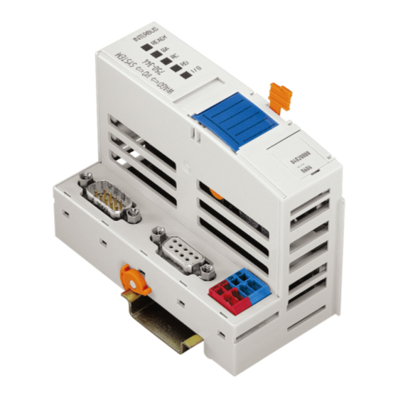
48 • Feldbus Coupler 750-344 / -345 Hardware 3.1.2 Hardware 3.1.2.1 View Status indication INTERBUS -Fieldbus READY -Fieldbus node Fieldbus connection Data contacts D-Sub incoming 01 02 03 04 Marking area Fieldbus connection D-Sub outgoing Supply Configuration interface Fig. 3-1: INTERBUS ECO fieldbus coupler... -
Page 49: Power Supply
Feldbus Coupler 750-344 / -345 • 49 Hardware 3.1.2.2 Power Supply The power is supplied via terminals with CAGE CLAMP® connection. The power supply powers the system. I/O Modules 1 / 2 24 V 24 V 10 nF Electronic 3 / 4... -
Page 50: Fieldbus Connection
Feldbus Coupler 750-344 / -345 Hardware 3.1.2.3 Fieldbus Connection The WAGO-I/O SYSTEM 750 for INTERBUS is equipped with two 9-pole D-SUB connectors for fieldbus connection. INTERBUS makes a distinction between the "incoming" and "outgoing" interface. Input interface: 9 pole D-Sub (male) -
Page 51: Indicators
The "I/O" LED indicates both the internal bus / orange communication and occurring errors. 3.1.2.5 Configuration Interface The configuration interface is located behind the cover flap. It is used to communicate with WAGO-I/O-CHECK and for transmitting of firmware. open flap Configuration interface Fig. -
Page 52: Operating System
52 • Feldbus Coupler 750-344 / -345 Operating system 3.1.3 Operating system The system can be started up after configuring the INTERBUS Master system and after electrical installation of the fieldbus station. The coupler checks the data bus when power is applied. Following this the I/O modules and the present configuration is determined. -
Page 53: Process Image
Feldbus Coupler 750-344 / -345 • 53 Process Image 3.1.4 Process Image 3.1.4.1 Local Process Image After being switched on, the coupler identifies all I/O modules connected that supply or are expected to receive process data (data width or bit width > 0). In nodes analog and digital I/O modules can be fitted mixed. -
Page 54: Bus Modules Process Images On The Interbus
54 • Feldbus Coupler 750-344 / -345 Process Image Based on this break-down, the first addresses assigned in the configuration are reserved for analog inputs and outputs. Counting is from left to right, beginning with the first analog channel next to the bus coupler. -
Page 55: Di Modules
Feldbus Coupler 750-344 / -345 • 55 Process Image 3.1.4.3.3 4 DI Modules 750-402, 750-403, 750-408, 750-409, 750-414, 750-415, 750-422,750-423, 750-424 Process Image in [Bit] Input Output INTERBUS 3.1.4.3.4 8 DI Modules 750-430, 750-431 Process Image in [Bit] Input Output INTERBUS 3.1.4.3.5 2 DO Modules... -
Page 56: Do Modules
56 • Feldbus Coupler 750-344 / -345 Process Image 3.1.4.3.7 4 DO Modules 750-504, 750-516, 750-519 Process Image in [Bit] Input Output INTERBUS 3.1.4.3.8 8 DO Modules 750-530 Process Image in [Bit] Input Output INTERBUS 3.1.4.3.9 Supply modules 750-610, 750-611 (with diagnostics) -
Page 57: Ai Modules
Feldbus Coupler 750-344 / -345 • 57 Process Image 3.1.4.3.11 4 AI Modules 750-453, 750-455, 750-457, 750-459, 750-460, 750-463, 750-468 Process Image in [Byte] Input Output INTERBUS INTERBUS Mapping MOTOROLA Input Output Channel 1 Channel 2 Channel 3 Channel 4 3.1.4.3.12... -
Page 58: Ao Modules
58 • Feldbus Coupler 750-344 / -345 Process Image 3.1.4.3.13 4 AO Modules 750-551, 750-553, 750-555, 750-557, 750-559 Process Image in [Byte] Input Output INTERBUS INTERBUS Mapping MOTOROLA Input Output Channel 1 Channel 2 Channel 3 Channel 4 3.1.4.3.14 Counter Modules... -
Page 59: Pwm Modules
Feldbus Coupler 750-344 / -345 • 59 Process Image 3.1.4.3.15 PWM Modules 750-511 Process Image in [Byte] Input Output INTERBUS INTERBUS Mapping MOTOROLA Input Output Channel 1 Channel 2 3.1.4.3.16 SSI Transmitter Interface 750-630 Process Image in [Byte] Input Output... -
Page 60: Incremental Encoder Interface
60 • Feldbus Coupler 750-344 / -345 Process Image 3.1.4.3.17 Incremental Encoder Interface 750-631, 750-634, 750-637 Process Image in [Byte] Input Output INTERBUS INTERBUS Mapping MOTOROLA Input Output Channel 1 3.1.4.3.18 Digital Impulse Interface 750-635 Process Image in [Byte] Input... -
Page 61: Serial Interfaces
Feldbus Coupler 750-344 / -345 • 61 Process Image 3.1.4.3.19 Serial Interfaces 750-650, 750-651, 750-653, 750-654 Process Image in [Byte] Input Output INTERBUS 4 / 6 4 / 6 INTERBUS Mapping MOTOROLA Input Output Channel 1 D3 (6) D3 (6) -
Page 62: Configuration
3.1.5.1 INTERBUS Files Further information INTERBUS files for configuring I/O modules are available under item number 750-913 on disk, or at the WAGO Internet site. http://www.wago.com 3.1.5.2 ID Code During the ID cycle, which is performed for initialization of the INTERBUS system, the connected subscribers (slaves) "declare"... -
Page 63: Id Code To The Wago I/O System
INTERBUS ID codes makes it necessary to use more than one ID code. The WAGO INTERBUS coupler reports in as a remote bus subscriber with a variable length. The ID code 0x3c is set when power is switched on. This code is then... -
Page 64: Example
64 • Feldbus Coupler 750-344 / -345 Configuration 3.1.5.4 Example Allocation can be clearly illustrated here by a fieldbus node with a coupler and 18 I/O modules. Fig. 3-9: Application example g012234x I/O module Master addresses *) Inputs Outputs Power supply Digital input P32.0... - Page 65 Feldbus Coupler 750-344 / -345 • 65 Configuration I/O module Master addresses *) Inputs Outputs Digital output P29.0 Digital output P29.1 Digital output P29.2 Digital output P29.3 Digital output P29.4 Digital output P29.5 Digital output P29.6 Digital output P29.7 Power supply...
-
Page 66: Diagnostics
Feldbus Coupler 750-344 / -345 Diagnostics 3.1.6 Diagnostics 3.1.6.1 Standard Couplers 750-344 and 750-345 The bus coupler reports an error in the periphery to the master when there is a disturbance of data bus operation. The bus coupler cancels the error message when the error has been eliminated. -
Page 67: Diagnostics Word In The Process Output Image
Feldbus Coupler 750-344 / -345 • 67 Diagnostics 3.1.6.2.2 Diagnostics Word in the Process Output Image The diagnostics output word (first work in the process output image) has the following functions. Data bit Meaning Reserved (= 0) Reserved Delete diagnostics memory completely in the fieldbus coupler... -
Page 68: Diagnostics Word In The Process Input Image
68 • Feldbus Coupler 750-344 / -345 Diagnostics 3.1.6.2.3 Diagnostics Word in the Process Input Image The diagnostics input word (first work in the process input image) has the following functions. Data bit Meaning for module error Meaning for bus coupler error... -
Page 69: Processing Of The Supi3 Input Staterr
Feldbus Coupler 750-344 / -345 • 69 Diagnostics The error codes for module errors are explained in the following table: Error code Meaning 0000 No error 0001 0010 General error 0011 0100 0101 Fuse error (digital module) 0110 0111 1000... -
Page 70: Led Indication
70 • Feldbus Coupler 750-344 / -345 LED Indication 3.1.7 LED Indication For the on-site diagnostics the coupler has five LEDs, which display the operating status of the coupler or the complete node. Fig. 3-10: Indicators 750-344 g012232x 3.1.7.1 Fieldbus status... -
Page 71: Node Status
Feldbus Coupler 750-344 / -345 • 71 LED Indication 3.1.7.3 Node Status The I/O-LED indicates the operation of the node and signals faults occurring. Meaning green Data cycle on the internal bus No data cycle on the internal bus Hardware defect in the coupler... -
Page 72: Fault Message Via Blink Code Of The I/O Led
72 • Feldbus Coupler 750-344 / -345 LED Indication After eliminating the error, restart the coupler by turning the power supply off and on again. 3.1.7.4 Fault Message via Blink Code of the I/O LED Error Error description Solution Argument Error Code 1: Hardware and Configuration Error Compile buffer overflow. - Page 73 Feldbus Coupler 750-344 / -345 • 73 LED Indication Error Error description Solution Argument Error code 4: data error internal data bus Data error on data bus, data bus Switch off the power for the disrupted downstream of coupler. coupler. Connect the module...
-
Page 74: Fault Behavior
74 • Feldbus Coupler 750-344 / -345 Fault behavior 3.1.8 Fault behavior 3.1.8.1 Loss of fieldbus A fieldbus failure is indicated, for example, if the master is switched off or if the bus cable is interrupted. An error at the master can also result in a fieldbus failure. -
Page 75: Technical Data
Number of I/O points 4096 (dependent on master) Transmission medium certified CU cable Fieldbus segment length 400 m at 500 Kbit/s (750-344) 150 m at 2 Mbit/s (750-345) Baud rate 500 kBaud (750-344) 2 MBaud (750-345) Data transmission time with 10 slaves, approx. -
Page 76: O Modules
76 • I/O Modules 4 I/O Modules This manual does not contain a detailed description of the fieldbus independent WAGO-I/O-SYSTEM 750 I/O modules. Further information Refer to the standard manual or the specific data sheets for information about the I/O modules. -
Page 77: Interbus
12.8 km (certified copper cable) RS 485 with 9-pole D-Sub connector 100 km (fiber optic cable) Data transmission rate 500 kbit/s, Data transmission rate 2 Mbit/s, On each restart the master generates a current list of connected subscribers (slaves) WAGO-I/O-SYSTEM 750 INTERBUS... - Page 78 Fieldbus devices: WAGO-I/O-SYSTEM 752, I/O module, digital signals WAGO-I/O-SYSTEM 750, Modular I/O system, digital and analog signals The INTERBUS transmission protocol can be viewed as a large shift register. Each slave, with its input and output data, along with the position and width, is a set component of this shift register.
- Page 79 9 pole D-SUB (male) (female) Color coding DO - DO Yellow DO DO Green DI - DI Grey DI DI Pink Brown Cable Cable grip/ grip/ Hous- Hous- Fig. 5-2: Example of a remote bus cable g012235d WAGO-I/O-SYSTEM 750 INTERBUS...
-
Page 80: Interface Modules
PLC and the fieldbus devices. The software for configuration, commissioning and diagnostics is either included with the interface modules or PC interface cards, or is available from other manufacturers as an accessory item. WAGO-I/O-SYSTEM 750 INTERBUS... - Page 81 INTERBUS • 81 WAGO-I/O-SYSTEM 750 INTERBUS...
Need help?
Do you have a question about the 750-344 and is the answer not in the manual?
Questions and answers