
Related Manuals for Ametek DR6500

Summary of Contents for Ametek DR6500
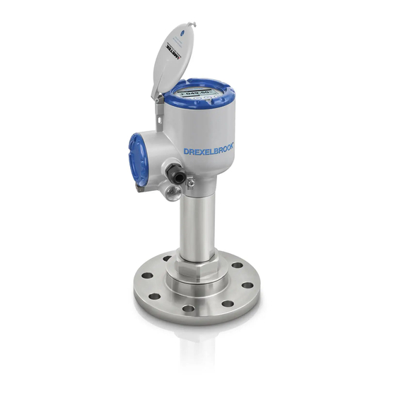
- Page 1 DR6500 DR6500 DR6500 DR6500 Handbook Handbook Handbook Handbook 80 GHz Radar (FMCW) Level Transmitter for powders and dusty atmosphere © AMETEK Drexelbrook - DR6500-PM-English-Issue 1...
- Page 2 IMPRINT :::::::::::::::::::::::::::::::::: All rights reserved. It is prohibited to reproduce this documentation, or any part thereof, without the prior written authorisation of AMETEK Drexelbrook. Subject to change without notice. Copyright 2019 by AMETEK Drexelbrook www.drexelbrook.co 01/2019 - DR6500-PM-English-Issue 1...
-
Page 3: Table Of Contents
3.10 How to turn or remove the display module (option) ............ 35 3.11 Weather protection....................... 36 3.11.1 How to attach the weather protection to the device............36 3.11.2 How to open the weather protection .................. 38 4 Electrical connections 4.1 Safety instructions......................39 DR6500-PM-English-Issue 1 www.drexelbrook.com... - Page 4 6.4.8 How to make a filter to remove radar signal interference ..........104 6.5 Status messages and diagnostic data................105 7 Service 7.1 Periodic maintenance....................112 7.1.1 General notes........................112 7.1.2 Maintenance of the O-rings for the housing covers............112 www.drexelbrook.co DR6500-PM-English-Issue 1...
- Page 5 9.10 HART® menu tree for PDM..................146 9.10.1 Overview PDM menu tree (positions in menu tree)............146 9.10.2 PDM menu tree (details for settings) ................147 10 Appendix 10.1 Order code ........................150 10.2 Spare parts ......................... 155 DR6500-PM-English-Issue 1 www.drexelbrook.com...
- Page 6 CONTENTS DR6500 10.3 Accessories: general items..................157 10.4 Accessories: process connection kits................ 158 10.5 Accessories: purging system adaptor................ 160 10.6 Glossary ........................161 www.drexelbrook.co DR6500-PM-English-Issue 1...
-
Page 7: Safety Instructions
— 2019-03-27 HMI (LCD display BL1.31.06 ER2.0.0_ 4002905801b DR6500-PM- option) Issue 1 Main and Support 4002815701f Sensor 4004742601b 1 If the device does not have the display module option, the module reference number is 4002905802a DR6500-PM-English-Issue 1 www.drexelbrook.com... -
Page 8: Intended Use
Declaration of Conformity. You can download this document free of charge from the website. All devices are based on the CE marking and meet the requirements of NAMUR Recommendations NE 21, NE 43, NE 53 and NE 107. www.drexelbrook.com DR6500-PM-English-Issue 1... -
Page 9: Radio Approvals
2 HVIN (Hardware Version Identification Number). This number gives the radar signal frequency (80GHZ = 80 GHz), the location of the device (T=TLPR or L=LPR) and the type of signal converter (compact (C)) TLPR device: HVIN: 80GHZ-T-C LPR device: HVIN: 80GHZ-L-C 3 CE sign DR6500-PM-English-Issue 1 www.drexelbrook.com... - Page 10 Plateau de Bure 44°38'01" N 05°54'26" E Germany Effelsberg 50°31'32" N 06°53'00" E Italy Sardinia 39°29'50" N 09°14'40" E Spain Yebes 40°31'27" N 03°05'22" W Pico Veleta 37°03'58" N 03°23'34" W Sweden Onsala 57°23’45" N 11°55’35" E www.drexelbrook.com DR6500-PM-English-Issue 1...
-
Page 11: U.s.a
Connect the equipment into an outlet on a circuit different from that to which the receiver is • connected. Consult the dealer or an experienced radio/TV technician for help. • The Product Marketing Name (PMN) of this device is "DRx500 series". DR6500-PM-English-Issue 1 www.drexelbrook.com... - Page 12 2 HVIN (Hardware Version Identification Number). This number gives the radar signal frequency (80GHZ = 80 GHz), the location of the device (T=TLPR or L=LPR) and the type of signal converter (compact (C)) TLPR device: HVIN: 80GHZ-T-C LPR device: HVIN: 80GHZ-L-C 3 FCC ID TLPR device: FCC-ID: Q6BFMCW80G74TA LPR device: FCC-ID: Q6BFMCW80G74LA www.drexelbrook.com DR6500-PM-English-Issue 1...
-
Page 13: Canada
The Director of the DRAO may be contacted at 250-497-2300 (tel.) or 250-497-2355 (fax). Alternatively, the Manager, Regulatory Standards, Industry Canada, may be contacted. The Product Marketing Name (PMN) of this device is "DRx500 series". DR6500-PM-English-Issue 1 www.drexelbrook.com... - Page 14 2 HVIN (Hardware Version Identification Number). This number gives the radar signal frequency (80GHZ = 80 GHz), the location of the device (T=TLPR or L=LPR) and the type of signal converter (compact (C)) TLPR device: HVIN: 80GHZ-T-C LPR device: HVIN: 80GHZ-L-C 3 IC number TLPR device: 1991D-FMCW80GX5T LPR device: 1991D-FMCW80GX5L www.drexelbrook.com DR6500-PM-English-Issue 1...
-
Page 15: Safety Instructions From The Manufacturer
The manufacturer reserves the right to alter the content of its documents, including this disclaimer in any way, at any time, for any reason, without prior notification, and will not be liable in any way for possible consequences of such changes. DR6500-PM-English-Issue 1 www.drexelbrook.com... -
Page 16: Product Liability And Warranty
This document is provided to help you establish operating conditions, which will permit safe and efficient use of this device. Special considerations and precautions are also described in the document, which appear in the form of icons as shown below. www.drexelbrook.com DR6500-PM-English-Issue 1... -
Page 17: Warnings And Symbols Used
In general, devices from the manufacturer may only be installed, commissioned, operated and maintained by properly trained and authorized personnel. This document is provided to help you establish operating conditions, which will permit safe and efficient use of this device. DR6500-PM-English-Issue 1 www.drexelbrook.com... -
Page 18: Device Description
1 Signal converter, process connection and antenna in the ordered version 2 Quick Start and supplementary instructions (if the device has the appropriate options) 3 Bar magnet 4 Display extractor (for removal of the optional display module) 5 Cover wrench (for removal of the device covers) www.drexelbrook.com DR6500-PM-English-Issue 1... -
Page 19: Device Description
Dimensions and weights on page 130 INFORMATION! Accessories: Accessories: Accessories: Accessories: For more data about general items, refer to Accessories: general items on page 157 . For more Accessories: process connection kits on page 158 data about process connections, refer to DR6500-PM-English-Issue 1 www.drexelbrook.com... -
Page 20: Visual Check
Look at the device nameplate to ensure that the device is delivered according to your order. Check for the correct supply voltage printed on the nameplate. INFORMATION! Compare the material references on the side of the process connection with the order. www.drexelbrook.com DR6500-PM-English-Issue 1... -
Page 21: Nameplates
11 cQPSus electrical safety certification for the USA and Canada. Agrees with NEC and CEC requirements for installa- tion in ordinary locations. 12 WARNING! Hot surface. If the device is connected to tank that operates at high temperature, there is a risk of injury. DR6500-PM-English-Issue 1 www.drexelbrook.com... -
Page 22: Installation
2 Put the device on its side. We recommend that you use the packaging in which it was delivered. 3 Storage temperature range: -40...+85°C / -40...+185°F • Store the device in a dry and dust-free location. • Keep the converter out of the sunlight. • Store the device in its original packing. www.drexelbrook.com DR6500-PM-English-Issue 1... -
Page 23: Transport
• Protect the signal converter from direct sunlight. If necessary, install the weather protection accessory. • Do not subject the signal converter to heavy vibrations. The devices are tested for vibration and agree with EN 50178 and IEC 60068-2-6. DR6500-PM-English-Issue 1 www.drexelbrook.com... -
Page 24: Pressure And Temperature Ranges
1 If the process connection temperature is more than +150°C / +302°F, the device has a distance piece. For more data about the overall dimensions of the device, refer to the "Dimensions and weights section". Guidelines for maximum operating pressure For more data on pressure ratings, refer to on page 128. www.drexelbrook.com DR6500-PM-English-Issue 1... -
Page 25: Recommended Mounting Position
If there is a nozzle on the tank before installation, the nozzle must be a minimum of 200 mm / ¨ from the tank wall. The tank wall must be flat and there must not be obstacles adjacent to the nozzle or on the tank wall. DR6500-PM-English-Issue 1 www.drexelbrook.com... - Page 26 Figure 3-6: There is no maximum limit to the number of devices that can be operated in the same silo There is no maximum limit to the number of devices that can be operated in the same silo. They can be installed adjacent to other radar level transmitters. www.drexelbrook.com DR6500-PM-English-Issue 1...
-
Page 27: Tanks With Dish-Shaped And Conical Bottoms
Causes of interference signals • Objects in the tank or silo. • Sharp corners that are perpendicular to the path of the radar beam. • Sudden changes in tank diameter in the path of the radar beam. DR6500-PM-English-Issue 1 www.drexelbrook.com... - Page 28 2 Beam radius of the antenna: refer to the table below. The beam radius increases by increments of "x" mm for each metre of distance from the antenna. Beam radius of the antenna Antenna type Beam angle Beam radius, x [mm/m] [in/ft] Lens, DN40 (1½¨) 8° Lens, DN70 (2¾¨) 4° www.drexelbrook.com DR6500-PM-English-Issue 1...
-
Page 29: Process Connections
For more data about the measuring range of each type of antenna, refer to Measuring accuracy on page 124 3.7.2 Process connections Flange connections: installation procedure Figure 3-10: Flange connections: installation procedure Ød = nozzle diameter h = nozzle height DR6500-PM-English-Issue 1 www.drexelbrook.com... - Page 30 Antenna extensions for devices with flanges Antenna extensions for devices with flanges If the device has an antenna extension, this option extends the maximum nozzle height. The antenna extension has a length of 112 mm / 4.4 ¨ www.drexelbrook.com DR6500-PM-English-Issue 1...
- Page 31 Antenna extensions for devices with threaded connections Antenna extensions for devices with threaded connections If the device has an antenna extension, this option extends the maximum nozzle height. The antenna extension has a length of 112 mm / 4.4 ¨ DR6500-PM-English-Issue 1 www.drexelbrook.com...
-
Page 32: Orientation System (Accessory)
ISO 228-1 (G) connection: dimensions and the process. Align the gasket correctly. • NPT connection: NPT connection: NPT connection: Wind the thread seal tape around the process connection of the device in NPT connection: agreement with good engineering practice. www.drexelbrook.com DR6500-PM-English-Issue 1... -
Page 33: How To Tilt The Device
If it is necessary to clean the Lens antenna, you can attach a purging system adaptor to the device. This part is available as an accessory for devices with threaded connections. INFORMATION! The purging system adaptor has an inlet with a G 1/4 threaded connection. DR6500-PM-English-Issue 1 www.drexelbrook.com... - Page 34 29.5 lbf·ft) with a 65 mm (G 1½ / 1½ NPT) and a 105 mm (G 3 / 3 NPT) open-end wrench. End of the procedure. INFORMATION! If it is necessary to send an order for the purging system adaptor, refer to Accessories: process connection kits on page 158 www.drexelbrook.com DR6500-PM-English-Issue 1...
-
Page 35: How To Turn Or Remove The Display Module (Option)
Equipment needed: • Cover wrench • Display extractor CAUTION! Disconnect the power supply. Follow this procedure: • Remove the housing cover with the cover wrench. • Find the two clips that hold the display module in the housing. DR6500-PM-English-Issue 1 www.drexelbrook.com... -
Page 36: Weather Protection
1 Weather protection cover (with an R-clip to hold the cover on the clamp) 2 Device 3 Weather protection clamp (2 parts) 4 2 locking nuts 5 10 mm socket wrench (not supplied) The overall dimensions of the weather protection are on page 130. www.drexelbrook.com DR6500-PM-English-Issue 1... - Page 37 3 Lower the weather protection cover onto weather protection clamp until the hole for the lock is in the slot at the front of the cover. 4 Put the R-clip into the hole at the front of the weather protection cover. 5 End of the procedure. DR6500-PM-English-Issue 1 www.drexelbrook.com...
-
Page 38: How To Open The Weather Protection
Figure 3-18: How to open the weather protection 1 Remove the R-clip from the hole at the front of the weather protection cover. 2 Remove the weather protection cover. 3 Lift the display screen cover. End of the procedure. www.drexelbrook.com DR6500-PM-English-Issue 1... -
Page 39: Electrical Connections
Devices with the PROFIBUS PA output option: Devices with the PROFIBUS PA output option: Devices with the PROFIBUS PA output option: Devices with the PROFIBUS PA output option: For electrical connection data, refer to the "Description of PROFIBUS PA interface" supplementary instructions. DR6500-PM-English-Issue 1 www.drexelbrook.com... -
Page 40: Electrical Installation: Output Options With Cable Gland
Use the applicable electrical cables with the cable glands. • Make sure that the current is not more than 5 A or that there is 5 A-rated fuse in the • electrical circuit that energizes the device. www.drexelbrook.com DR6500-PM-English-Issue 1... - Page 41 • 3 mm Allen wrench (not supplied) • Cover wrench Procedure 1 Loosen the lock screw with a 3 mm Allen wrench. 2 Remove the cover stop. 3 Turn the cover counterclockwise with the cover wrench. 4 Remove the cover. DR6500-PM-English-Issue 1 www.drexelbrook.com...
- Page 42 1 Loosen the cable gland. Put the electrical wires into the cable entry. Loosen the terminal screws with a POZIDRIV® PZ1 screwdriver. Connect the electrical wires to the connector. 2 Tighten the terminal screws with a POZIDRIV® PZ1 screwdriver. 3 Tighten the cable gland. www.drexelbrook.com DR6500-PM-English-Issue 1...
- Page 43 • 3 mm Allen wrench (not supplied) 1 Put the cover on the housing 2 Turn the cover clockwise until it is fully engaged. 3 Attach the cover stop and lock screw. 4 Tighten the lock screw with a 3 mm Allen wrench. DR6500-PM-English-Issue 1 www.drexelbrook.com...
-
Page 44: Electrical Installation: Output Options With An M12 Male Connector
Figure 4-6: Electrical connections for non-Ex devices 1 Power supply 2 Resistor for HART® communication (typically 250 ohms) 3 Optional connection to the grounding terminal 4 Output: 12...30 VDC for an output of 21.5 mA at the terminal 5 Device www.drexelbrook.com DR6500-PM-English-Issue 1... -
Page 45: Devices For Hazardous Locations
• Tighten the cable glands 2. • Close unused cable glands with dummy plugs 3. The diameter of the outer sheath of the electrical cable (for the power supply and current output) must be 6…10 mm or 0.24…0.39¨. DR6500-PM-English-Issue 1 www.drexelbrook.com... -
Page 46: Networks
Figure 4-8: Point-to-point connection (non-Ex) 1 Address of the device (0 for point-to-point connection) 2 4...20 mA + HART® 3 Resistor for HART® communication (typically 250 ohms) 4 Power supply 5 HART® converter 6 HART® communication software www.drexelbrook.com DR6500-PM-English-Issue 1... -
Page 47: Multi-Drop Networks
1 Address of the device (each device must have a different address in multidrop networks) 2 4 mA + HART® 3 Resistor for HART® communication (typically 250 ohms) 4 Power supply 5 HART® converter 6 HART® communication software DR6500-PM-English-Issue 1 www.drexelbrook.com... -
Page 48: Start-Up
• Energize the converter. Devices with the LCD display option only: Devices with the LCD display option only: After 10 seconds the screen will display "DR6500" Devices with the LCD display option only: Devices with the LCD display option only: and the logo of the supplier. -
Page 49: Digital Display Screen
Function (2nd Meas. Page). If menu item C6.4.2 1st Value Variable (1st Meas. page) is set to "Level", then the device shows "Level" as the current output percentage in Normal mode (refer to item 1 in the illustration). DR6500-PM-English-Issue 1 www.drexelbrook.com... -
Page 50: Keypad Buttons
Normal mode: Change screen (measurement pages 1 and 2 and [Up] the status message page) Program mode: Program mode: Increase value or change parameter Program mode: Program mode: Keypad functions For more data on keypad functions, refer to on page 62. www.drexelbrook.com DR6500-PM-English-Issue 1... - Page 51 2 Push the buttons on the keypad. This will operate the device. How to operate the keypad buttons with a bar magnet Figure 5-4: How to operate the keypad buttons with a bar magnet Equipment needed • Bar magnet DR6500-PM-English-Issue 1 www.drexelbrook.com...
-
Page 52: Remote Communication With Pactware
You can download the latest version of PACTware™ and the DTM from our website. Refer also to the PACTware Consortium site at http://www.pactware.com. Figure 5-5: Screen from the PACTware™ user interface 1 DTM menu 2 Information for device identification 3 Installation parameters menu and menu items www.drexelbrook.com DR6500-PM-English-Issue 1... -
Page 53: Remote Communication With The Ams™ Device Manager
• Store configuration information for each device. • Store and read process data. • Store and read diagnostic status information. • Help plan preventive maintenance to reduce a plant's downtime to a minimum. You can download the DD file from our website. DR6500-PM-English-Issue 1 www.drexelbrook.com... -
Page 54: Operation
1 One value 2 One value and % bar graph of the scale for the measurement value 3 Two values 4 Two values and % bar graph of the scale for the top measurement value 5 Three values www.drexelbrook.com DR6500-PM-English-Issue 1... - Page 55 For a list of the abbreviations used in Normal mode, refer to the table that follows: Abbreviations of measurement types used in Normal mode Measurement type Abbreviation Distance Level Reflection Sensor value Volume Ullage volume Mass Ullage mass UllM Linearized distance Ldis or Distance Lin. Linearized level LLvl or Level Lin. DR6500-PM-English-Issue 1 www.drexelbrook.com...
- Page 56 [^ ^ ^ ^ ] — [Return] [> > > > ]+[ ] — [Escape] Change screen (measurement pages 1 and 2, and the status [Down] message page) Change screen (measurement pages 1 and 2 and the status [Up] message page) www.drexelbrook.com DR6500-PM-English-Issue 1...
- Page 57 It is the distance from the face of the process ft (feet), custom length unit connection (flange face or thread stop) to the surface of the liquid. You cannot change this value in Program mode. Refer also to "Distance" in this table. DR6500-PM-English-Issue 1 www.drexelbrook.com...
-
Page 58: Program Mode
If you did not supply all installation data to the supplier before the delivery, the standard setup procedure in the Quick Setup menu is mandatory. INFORMATION! It is not possible to enter the D Service D Service D Service D Service menu. This menu is for factory calibration and approved personnel only. www.drexelbrook.com DR6500-PM-English-Issue 1... -
Page 59: Protection Of The Device Settings (Access Levels)
• Push 2 × [ ], [> > > > ], 5 × [ ], [> > > > ], [ ] and [> > > > ] to go to the menu C7.2 Security. • Push [> > > > ] to enter menu item C7.2.1 Login. DR6500-PM-English-Issue 1 www.drexelbrook.com... - Page 60 If you de-energize the device and then energize it again, the access level will go back to "User". If you do not touch the keypad for 5 minutes, the device goes back to Normal mode and the access level will go back to "User". www.drexelbrook.com DR6500-PM-English-Issue 1...
-
Page 61: How To Get Access To The Quick Setup Menu
• Push [> > > > ] to start the empty spectrum recording procedure. For more data, refer to spectrum recording on page 93. Push [^ ^ ^ ^ ] at the end of each step of the procedure to continue to the next step. • End of the procedure. DR6500-PM-English-Issue 1 www.drexelbrook.com... -
Page 62: Keypad Functions
Scroll down the sub-menu list (for example, from sub-menu C2.1 to sub-menu C2.2). • Scroll up the menu list (for example, from menu C2 to menu C1). • Scroll up the sub-menu list (for example, from sub-menu C2.2 to sub-menu C2.1). www.drexelbrook.com DR6500-PM-English-Issue 1... - Page 63 Select the parameter and go back to the menu Esc (Escape) If you push these buttons immediately after you change a parameter, the device also ignores this change and goes back to the menu. Down Scroll down the list Scroll up the list DR6500-PM-English-Issue 1 www.drexelbrook.com...
- Page 64 If the cursor is on a number, this button increases the digit value. If the cursor is on the decimal point, this button moves the decimal point to the right (this increases the value by a factor of 10). www.drexelbrook.com DR6500-PM-English-Issue 1...
-
Page 65: How To Save Settings Changed In Program Mode
"Yes" or No", push [^ ^ ^ ^ ] to accept (Yes) or reject (No) the new settings. If you push [^ ^ ^ ^ ] when the screen is set to "Yes" or No", the display goes back to Normal mode. DR6500-PM-English-Issue 1 www.drexelbrook.com... -
Page 66: Menu Overview
A4.2.1.5 Start Recording? A4.2.1.6 Recording Empty Spectrum Data A4.2.1.10 Empty Spectrum Graph A4.2.1.11 Save Spectrum? A4.2.1.12 Empty Spectrum Enable 1 The device shows this menu item if you set the menu item A4.2.1.1 to "Partial, Average" or "Partial, Max" www.drexelbrook.com DR6500-PM-English-Issue 1... - Page 67 Spectrum 1 You must enter the "Expert" password in A3 Login or C7.2.1 Login to find and use this menu 2 The device shows this menu item if you make a strapping table in menu C.3 Conversion DR6500-PM-English-Issue 1 www.drexelbrook.com...
- Page 68 C4.1 Current Output 1 1 1 1 C4.1.2 0% Range C4.1.3 100% Range C4.1.4 Current Out. Range C4.1.5 Error Function C4.1.7 Low Error Current C4.1.8 High Error Current C4.1.9.2 Trimming / 4mA Trimming C4.1.9.5 Trimming / 20mA Trimming www.drexelbrook.com DR6500-PM-English-Issue 1...
- Page 69 Current Out. 1 Var. C5.1.4.2 HART Variables / HART sec./CO2 Var. C5.1.4.3 HART Variables / Tertiary Var. C5.1.4.4 HART Variables / Quaternary Var. C6 Display C6 Display C6.1 Language C6 Display C6 Display C6.2 Backlight C6.3 Contrast DR6500-PM-English-Issue 1 www.drexelbrook.com...
- Page 70 C7.2 Security C7.2 Security C7.2 Security C7.2.1 Login C7.2.2 Change Password C7.2.3 Reset Passwords C7.2.4 Unlock Extended Range C7.2.5 Unlock SIL C7.3 Errors C7.3 Errors C7.3.1 Message View C7.3 Errors C7.3 Errors C7.3.2.1 Error-Mapping / Sensor: Information www.drexelbrook.com DR6500-PM-English-Issue 1...
-
Page 71: Function Description
Refer to to change settings. If you do not enter "Function the password, you can only change description" settings for the "user" access level. Protection of For more data, refer to the device settings (access levels) page 59. DR6500-PM-English-Issue 1 www.drexelbrook.com... - Page 72 "How to make a filter to remove radar signal interference" on page 104. Minimum access level to do the Minimum access level to do the Minimum access level to do the Minimum access level to do the procedure: procedure: Expert procedure: procedure: www.drexelbrook.com DR6500-PM-English-Issue 1...
- Page 73 The device goes to back to Normal mode after 1 hour. Minimum access level to do the Minimum access level to do the Minimum access level to do the Minimum access level to do the procedure: procedure: procedure: procedure: Expert DR6500-PM-English-Issue 1 www.drexelbrook.com...
- Page 74 The device goes to back to Normal mode after 1 hour. Minimum access level to do the Minimum access level to do the Minimum access level to do the Minimum access level to do the procedure: procedure: procedure: procedure: Expert www.drexelbrook.com DR6500-PM-English-Issue 1...
- Page 75 The device goes to back to Normal mode after 1 hour. Minimum access level to do the Minimum access level to do the Minimum access level to do the Minimum access level to do the procedure: procedure: procedure: procedure: Expert DR6500-PM-English-Issue 1 www.drexelbrook.com...
- Page 76 C7.5 Units C7.5 Units C7.5 Units C7.5 Units. This menu item is only available if you set up a linearization table in menu item C3.1 Edit Table C3.1 Edit Table C3.1 Edit Table C3.1 Edit Table. www.drexelbrook.com DR6500-PM-English-Issue 1...
- Page 77 It is also possible to do an empty spectrum scan in a partially full tank, if it is not possible to remove all the tank contents. 1 The default value is the measured value at the time that you start the simulation DR6500-PM-English-Issue 1 www.drexelbrook.com...
- Page 78 Each segment is 105 mm / 4.1¨ long. 0.0...6.5617 ft Minimum access level to change the Minimum access level to change the Minimum access level to change the Minimum access level to change the setting: setting: Expert setting: setting: www.drexelbrook.com DR6500-PM-English-Issue 1...
- Page 79 Refer also to "Measuring principle" on page 116. Minimum access level to change the Minimum access level to change the Minimum access level to change the Minimum access level to change the setting: setting: Expert setting: setting: DR6500-PM-English-Issue 1 www.drexelbrook.com...
- Page 80 (menu A4.2) in the Quick Setup menu. Minimum access level to change the Minimum access level to change the Minimum access level to change the Minimum access level to change the setting: setting: setting: setting: Expert www.drexelbrook.com DR6500-PM-English-Issue 1...
- Page 81 Minimum access level to do the procedure: Minimum access level to do the procedure: Minimum access level to do the procedure: Minimum access level to do the procedure: 0.0 mm / 0.0¨ 0.0...100.0 kg / Expert 0.0...220.46 Linearization: 0.0...100.0 mm / 0.0...3.937 ¨ DR6500-PM-English-Issue 1 www.drexelbrook.com...
- Page 82 C4.1.8. Minimum access level to change the Minimum access level to change the Minimum access level to change the Minimum access level to change the setting: setting: Expert setting: setting: www.drexelbrook.com DR6500-PM-English-Issue 1...
- Page 83 62 (values in menu items). Minimum access level to change the Minimum access level to change the Minimum access level to change the Minimum access level to change the setting: setting: Operator setting: setting: DR6500-PM-English-Issue 1 www.drexelbrook.com...
- Page 84 HART® controllers. Make a selection Value, Reflection from the list. Minimum access level to change the Minimum access level to change the Minimum access level to change the Minimum access level to change the setting: setting: setting: setting: Expert www.drexelbrook.com DR6500-PM-English-Issue 1...
- Page 85 "One Value & Bar" or "Two Values & Bar". Minimum access level to change the Minimum access level to change the Minimum access level to change the Minimum access level to change the setting: setting: setting: setting: User DR6500-PM-English-Issue 1 www.drexelbrook.com...
- Page 86 "Automatic", the device will adjust the number of decimal places automatically. Minimum access level to change the Minimum access level to change the Minimum access level to change the Minimum access level to change the setting: setting: setting: setting: User www.drexelbrook.com DR6500-PM-English-Issue 1...
- Page 87 "Automatic", the device will adjust the number of decimal places automatically. Minimum access level to change the Minimum access level to change the Minimum access level to change the Minimum access level to change the setting: setting: User setting: setting: DR6500-PM-English-Issue 1 www.drexelbrook.com...
- Page 88 4-digit hexadecimal Refer to Password "operator" and "expert" access levels. For password "Function the procedure to change the password, description" Protection of the device settings refer to (access levels) on page 59 (How to change the password). www.drexelbrook.com DR6500-PM-English-Issue 1...
- Page 89 — Cst. custom volume unit. — C7.5.4.2 Offset Enter an offset value. 0.0 m³ C7.5.4.3 Factor Enter a factor. Multiply the measured value — by this factor to change m³ (cubic metres) to the custom volume unit. DR6500-PM-English-Issue 1 www.drexelbrook.com...
-
Page 90: Further Information On Device Configuration In Program Mode
C6.4 1st Meas. Page and C6.5 2nd Meas. Page menus. For more data, refer to Function description on page 71 table C. Full Setup menu (C6 Display). – www.drexelbrook.com DR6500-PM-English-Issue 1... - Page 91 (Ullage Volume). If it is necessary to measure volume, ullage • volume, mass or ullage mass, refer to [^ ^ ^ ^ ] to confirm. to configure the device to measure volume or mass on page 101. DR6500-PM-English-Issue 1 www.drexelbrook.com...
- Page 92 0% Range = 4 mA • 100% Range = 20 mA If you set this menu item to "4-20 mA (reversed)" or "3.8-20.5 mA (reversed)": • 0% Range = 20 mA • 100% Range = 4 mA www.drexelbrook.com DR6500-PM-English-Issue 1...
-
Page 93: Empty Spectrum Recording
22. Values and parameters that can be changed are shown between the « ... » marks in the illustrations that follow. Push the keypad buttons in the correct sequence: DR6500-PM-English-Issue 1 www.drexelbrook.com... - Page 94 Start recording? Set this menu item to "Yes" to continue to the subsequent step. ("No" or "Yes"). Set this menu item to "No" to go back to the • [^ ^ ^ ^ ] to confirm. menu. www.drexelbrook.com DR6500-PM-English-Issue 1...
- Page 95 Normal mode. Set • [^ ^ ^ ^ ] to confirm. to "No" to cancel the changes to the device settings and go back to Normal mode. Set to "Back" to stay in Program mode. DR6500-PM-English-Issue 1 www.drexelbrook.com...
-
Page 96: Hart® Network Configuration
"Value Variable" menu items in the C6.4 1st Measurement Page or C6.5 2nd Measurement Page menu are set to "Distance". Menu items related to distance measurement are: • Current output 1 menu (C4.1) • Tank Height (C1.2) www.drexelbrook.com DR6500-PM-English-Issue 1... - Page 97 CAUTION! If C4.1.1 Current Out. 1 Var. is set to "Distance" and C4.1.2 0% Range (standard scale) is set in the blocking distance, then the device will not be able to use the full current output range. DR6500-PM-English-Issue 1 www.drexelbrook.com...
- Page 98 C6.4.2 and C6.5.2 (1st Value Variable) and menu C1 Install. Parameters. If you change C1.10 Reference Offset, then we recommend that you change C6.4.3 / C6.5.3 (0% Range) and C6.4.4 / C6.5.4 (100% Range) by the same quantity. www.drexelbrook.com DR6500-PM-English-Issue 1...
-
Page 99: Level Measurement
CAUTION! If C4.1.1 Current Out. 1 Var. is set to "Level" and C4.1.3 100% Range (standard scale) is set in the blocking distance, then the device will not be able to use the full current output range. DR6500-PM-English-Issue 1 www.drexelbrook.com... - Page 100 C6.4.2 and C6.5.2 (1st Value Variable) and menu C1 Install. Parameters. If you change C1.11 Tank Bottom Offset, then we recommend that you change C6.4.3 / C6.5.3 (0% Range) and C6.4.4 / C6.5.4 (100% Range) by the same quantity. www.drexelbrook.com DR6500-PM-English-Issue 1...
-
Page 101: How To Configure The Device To Measure Volume Or Mass
Normal mode. The device will give more accurate volume readings if you give more conversion data in these areas: • Surfaces with curves. • Sudden changes in the cross section. Refer also to the illustration that follows: DR6500-PM-English-Issue 1 www.drexelbrook.com... - Page 102 "Yes" or No", push [^ ^ ^ ^ ] to accept (Yes) or reject (No) the new settings. If you push [^ ^ ^ ^ ] when the screen is set to "Yes", the device will delete the data for the strapping table and go back to Normal mode. www.drexelbrook.com DR6500-PM-English-Issue 1...
-
Page 103: How To Measure Correctly In Silos With Curved Or Conical Bottoms
• Select Yes Yes and push [^ ^ ^ ^ ]. The device will go back to Normal mode. INFORMATION! For more data on menu items, refer to Function description on page 71 table C: Full Setup. – DR6500-PM-English-Issue 1 www.drexelbrook.com... -
Page 104: How To Make A Filter To Remove Radar Signal Interference
INFORMATION! For more data on empty spectrum scans, refer to Function description on page 71 table A. – Quick Setup menu (menu item A4.2). www.drexelbrook.com DR6500-PM-English-Issue 1... -
Page 105: Status Messages And Diagnostic Data
Normal mode: device status symbol If the device status changes, the device shows a status symbol in the top left corner of the display screen in Normal mode: Figure 6-11: Device status: Normal mode 1 Device status symbol (NAMUR NE 107) DR6500-PM-English-Issue 1 www.drexelbrook.com... - Page 106 1 Device status letter code (NAMUR NE 107). In this example, M = Maintenance required. 2 Description of error If the device shows an error message, refer to the table that follows for more data and to find a solution to a problem. www.drexelbrook.com DR6500-PM-English-Issue 1...
- Page 107 Inconsistent Parameters Internal bus communication error. De-energize and then energize the device again. Sensor Comm. Error Internal bus communication error or hardware failure. If the message is shown again, tell the supplier. DR6500-PM-English-Issue 1 www.drexelbrook.com...
- Page 108 If the message is shown again, tell the supplier. C C C C Electronics Electronics Electronics Electronics FW Update A firmware update of the Wait for the firmware update to converter module continues. finish. www.drexelbrook.com DR6500-PM-English-Issue 1...
- Page 109 S S S S Electronics Electronics Electronics Electronics Elec. Temp. Out Of Spec. The temperature of the converter Make sure that the device is is not in the specified limits. operated in the permitted ambient temperature range. DR6500-PM-English-Issue 1 www.drexelbrook.com...
- Page 110 If the message is shown again, tell the supplier. Empty Spectrum invalid The empty spectrum recording Do a new empty spectrum does not agree with the process recording. conditions at this time (e.g. the tank height was changed). www.drexelbrook.com DR6500-PM-English-Issue 1...
- Page 111 Microwave Lock Error Microwave Sweep Duration Error Microwave Supply Voltage Error 1 DM = data manager 2 CO = current output 3 This error message is shown if the device is in SIL mode. CO = current output. DR6500-PM-English-Issue 1 www.drexelbrook.com...
-
Page 112: Service
O-rings are correctly greased or, if it is necessary, replaced. For more data Spare parts about the replacement of the O-rings, refer to on page 155. Figure 7-1: Maintenance of the O-rings 1 Display cover 2 Terminal compartment cover www.drexelbrook.com DR6500-PM-English-Issue 1... -
Page 113: How To Clean The Top Surface Of The Device
3 years after delivery of the last production run for the device. This regulation only applies to spare parts which are subject to wear and tear under normal operating conditions. DR6500-PM-English-Issue 1 www.drexelbrook.com... -
Page 114: Availability Of Services
• such dangerous substances, • to enclose a certificate with the device confirming that it is safe to handle and stating the product used. www.drexelbrook.com DR6500-PM-English-Issue 1... -
Page 115: Form (For Copying) To Accompany A Returned Device
The user must dispose of the WEEE to a designated collection point for the recycling of WEEE or send them back to our local organisation or authorised representative. DR6500-PM-English-Issue 1 www.drexelbrook.com... -
Page 116: Technical Data
1 Transmitter 2 Mixer 3 Antenna 4 Distance to product surface, where change in frequency is proportional to distance 5 Differential time delay, Δt 6 Differential frequency, Δf 7 Frequency transmitted 8 Frequency received 9 Frequency 10 Time www.drexelbrook.com DR6500-PM-English-Issue 1... - Page 117 The interference signal must not be near to the level signal. CAUTION! "DIRECT PLUS" MODES It is important to enter the correct dielectric constant value in menu item C2.2 Epsilon R Product. If this value is incorrect, the device will not measure level accurately. DR6500-PM-English-Issue 1 www.drexelbrook.com...
-
Page 118: Technical Data
Standard: ±2 mm / ±0.08¨, when distance ≤ 10 m / 33 ft; Accuracy ±0.02% of measured distance, when distance > 10 m / 33 ft. For more data, refer to Measuring accuracy on page 124. Digital temperature drift Max. ±10 mm / ±0.39¨ for the full temperature range www.drexelbrook.com DR6500-PM-English-Issue 1... -
Page 119: Operating Conditions
PTFE (≤ +150°C / +302°F); PEEK (> +150°C / +302°F) Gaskets FKM/FPM (-40…+150°C / -40…+302°F); EPDM (-50°C…+150°C / -58…+302°F) Cable gland Standard: none Options: Plastic (Non-Ex: black, Ex i-approved: blue); nickel-plated brass; stainless steel; M12 (4-pin connector) Weather protection (Option) Stainless steel (1.4404 / 316L) DR6500-PM-English-Issue 1 www.drexelbrook.com... - Page 120 127. Standard: M20×1.5; Options: ½ NPT; 4-pin male M12 connector Cable entry Cable gland Standard: none Options: M20×1.5 (cable diameter: 7…12 mm / 0.28…0.47¨); others are available on request Cable entry capacity (terminal) 0.5…3.31 mm² (AWG 20...12) www.drexelbrook.com DR6500-PM-English-Issue 1...
- Page 121 1 × Transducer Block Level (TB-Level), 1 × Physical Block (PB), 4 × Analog Input Block (AI), 1 × Totalizer Function Block (TOT) 9...32 V DC – bus powered; no additional power supply required Device power supply Polarity sensitivity Basic current 18 mA DR6500-PM-English-Issue 1 www.drexelbrook.com...
- Page 122 Electrical safety EU: Agrees with the safety part of the Low Voltage directive (LVD) USA and Canada USA and Canada USA and Canada USA and Canada: Agrees with NEC and CEC requirements for installation in ordinary locations www.drexelbrook.com DR6500-PM-English-Issue 1...
- Page 123 For more data, refer to the website. Construction code Option: ASME B31.3 1 HART® is a registered trademark of the HART Communication Foundation 2 T*°C = 150°C or 200°C. For more data, refer to the related Ex approval certificate. DR6500-PM-English-Issue 1 www.drexelbrook.com...
-
Page 124: Measuring Accuracy
Figure 8-2: DN40 (1½¨) Lens antenna: measuring accuracy (graph of measuring accuracy in mm against measuring distance in m) X: Measuring distance from the thread stop or flange facing of the process connection [m] Y: Measuring accuracy [+yy mm / -yy mm] 1 50 mm 2 200 mm www.drexelbrook.com DR6500-PM-English-Issue 1... - Page 125 X: Measuring distance from the thread stop or flange facing of the process connection [ft] Y: Measuring accuracy [+yy inches / -yy inches] 1 1.97¨ 2 7.87¨ INFORMATION! To calculate the accuracy at a given distance from the antenna, refer to Technical data on page (measuring accuracy). DR6500-PM-English-Issue 1 www.drexelbrook.com...
- Page 126 X: Measuring distance from the thread stop or flange facing of the process connection [ft] Y: Measuring accuracy [+yy inches / -yy inches] 1 3.94¨ INFORMATION! To calculate the accuracy at a given distance from the antenna, refer to Technical data on page (measuring accuracy). www.drexelbrook.com DR6500-PM-English-Issue 1...
-
Page 127: Minimum Power Supply Voltage
Hazardous Location (Ex d / XP/NI) approved devices Figure 8-7: Minimum power supply voltage for an output of 21.5 mA at the terminals (Hazardous Location approval (Ex d / XP/NI)) X: Power supply U [V DC] Y: Current output load R [Ω] DR6500-PM-English-Issue 1 www.drexelbrook.com... -
Page 128: Guidelines For Maximum Operating Pressure
Figure 8-9: Pressure / temperature de-rating (EN 1092-1), flange and threaded connections, in °F and psig 1 Process pressure, p [barg] 2 Process connection temperature, T [°C] 3 Process pressure, p [psig] 4 Process connection temperature, T [°F] 5 Threaded connection, G (ISO 228-1) 6 Flange connection, PN40 7 Flange connection, PN16 www.drexelbrook.com DR6500-PM-English-Issue 1... - Page 129 1 Process pressure, p [barg] 2 Process connection temperature, T [°C] 3 Process pressure, p [psig] 4 Process connection temperature, T [°F] 5 Threaded connection, NPT (ASME B1.20.1) 6 Flange connection, Class 300 7 Flange connection, Class 150 DR6500-PM-English-Issue 1 www.drexelbrook.com...
-
Page 130: Dimensions And Weights
The diameter of the outer sheath of the cable must be 7 … 12 mm or 0.28 … 0.47 ¨ • Cable glands for cQPSus-approved devices must be supplied by the customer. • A weather protection cover is available as an accessory with all devices. • www.drexelbrook.com DR6500-PM-English-Issue 1... - Page 131 2 If the process temperature is more than +302°F, add 4.41¨ to this value. If the device has the antenna extension option, add 4.41¨ to this value. 3 If the device has the antenna extension option, add 4.41¨ to this value DR6500-PM-English-Issue 1 www.drexelbrook.com...
- Page 132 The diameter of the outer sheath of the cable must be 7 12 mm or 0.28 0.47 • … … ¨ Cable glands for cQPSus-approved devices must be supplied by the customer. • A weather protection cover is available as an accessory with all devices. • www.drexelbrook.com DR6500-PM-English-Issue 1...
- Page 133 4 If the device has a G 3 process connection, then f = 0.92¨. If the device has a 3 NPT process connection, then f = 1.18¨. 5 If the process temperature is more than +302°F, add 4.41¨ to this value DR6500-PM-English-Issue 1 www.drexelbrook.com...
- Page 134 1 Front view (with weather protection closed) 2 Left side (with weather protection closed) 3 Rear view (with weather protection closed) Weather protection: Dimensions and weights Dimensions Weights [kg] [mm] [inch] [mm] [inch] [mm] [inch] [kg] [lb] Weather 6.97 6.02 8.50 protection www.drexelbrook.com DR6500-PM-English-Issue 1...
- Page 135 DN40 (1½¨) Lens antenna with DN80 PN16 / B1 or 3¨ 150 lb / RF flange and 2° PP 15.2 slanted flange DN70 (2¾¨) Lens antenna with DN80 PN16 / B1 or 3¨ 150 lb / RF flange and 2° PP 15.7 slanted flange DR6500-PM-English-Issue 1 www.drexelbrook.com...
-
Page 136: Description Of Hart Interface
An FSK or HART® modem is included in field devices and manual control units. It is necessary to have an external modem for PC-supported workstations. The external modem is connected to the serial or USB interface. www.drexelbrook.com DR6500-PM-English-Issue 1... -
Page 137: Software History
• as Multi-Drop connection with 2-wire connection. 9.3.1 Point-to-Point connection – analogue / digital mode Point-to-Point connection between the signal converter and the HART® Master. The current output of the device is passive. Point-to-point connection Also refer to on page 46. DR6500-PM-English-Issue 1 www.drexelbrook.com... -
Page 138: Multi-Drop Connection (2-Wire Connection)
The HART® dynamic variables PV (Primary Variable), SV (Secondary Variable), TV (Third Variable) and QV (Fourth Variable) can be assigned to any of the device variables. The HART® dynamic variable PV is always connected to the HART® current output which is, for example, assigned to level measurement. www.drexelbrook.com DR6500-PM-English-Issue 1... -
Page 139: Field Communicator 475 (Fc 475)
The online help for each menu item refers to the function number given to each menu item on the local device display. Protection of settings is the same as on the device's local display. The Field Communicator always saves a complete configuration for communication with AMS. DR6500-PM-English-Issue 1 www.drexelbrook.com... -
Page 140: Asset Management Solutions (Ams ® )
AMS and operating using the local keyboard. The service menu parameters are not supported and simulation is only possible for current outputs. The online help for each parameter contains its function number as a reference to the local device display. www.drexelbrook.com DR6500-PM-English-Issue 1... -
Page 141: Field Device Tool / Device Type Manager (Fdt / Dtm)
Refer to the online help in SIMATIC PDM to find the function number of each menu item. This function number agrees with the function number in the device menus. Use the same procedure for the protection of parameters in the supervisor menu. DR6500-PM-English-Issue 1 www.drexelbrook.com... -
Page 142: Hart® Menu Tree For Ams
Login / Change Password / Reset Passwords / Lock Status / Lock / Unlock Device / Write Protect (De)activate Write Protection / Unlock Extended Range Units Unit Length / Unit Volume / Unit Mass Application Standard Setup / Record Empty Spectrum Assistant www.drexelbrook.com DR6500-PM-English-Issue 1... - Page 143 Range / 100% Range 2nd Measurement Function / 1st Value Variable / Page Format 1st Value / 2nd Value Variable / Format 2nd Value / 3rd Value Variable Format 3rd Value / 0% Range / 100% Range DR6500-PM-English-Issue 1 www.drexelbrook.com...
- Page 144 / Number of response preambles Service Calibration Calibration Current Output 1 Sensor Manual Correction Offset / Manual Correction Factor / Correction Offset / Correction Factor Rd, Opt Correction Offset Extended Rd, Opt Correction Factor Extended www.drexelbrook.com DR6500-PM-English-Issue 1...
- Page 145 Opt, Rd Opt, Linearization / Volume / Mass / Distance Linearization Opt, Rd Opt, Rd / Ullage / Ullage Mass Inputs / Out / PV % Range / PV output current / SV / TV / QV DR6500-PM-English-Issue 1 www.drexelbrook.com...
-
Page 146: Hart® Menu Tree For Pdm
2nd Measurement Page Device Information Security Units Factory Default HART Identification & Info Service Calibration Calibration Sensor Overview: View Menu Measured Value Input / Outputs Overview: Diagnosis Device Status Condensed Status (NE 107) Standard Additional Cluster Check Actual Values www.drexelbrook.com DR6500-PM-English-Issue 1... -
Page 147: Pdm Menu Tree (Details For Settings)
/ 100% Range 2nd Measurement Function / 1st Value Variable / Format 1st Value / Page 2nd Value Variable / Format 2nd Value / 3rd Value VariableOpt / Format 3rd Value / 0% Range / 100% Range DR6500-PM-English-Issue 1 www.drexelbrook.com... - Page 148 / Level Linearization / Volume Opt, Rd Opt, Rd Opt, Rd Opt, Rd Mass / Distance Linearization / Ullage / Ullage Mass Input / Outputs / PV % Range / PV output current / SV / TV / QV www.drexelbrook.com DR6500-PM-English-Issue 1...
- Page 149 / Long Tag / Serial Number / Manufacturer / Device Name / V Number / Electronic Revision / Field Device Revision / Software Revision / Hardware Revision / Electronics Serial / Production Date / Calibration Date / Operating Time DR6500-PM-English-Issue 1 www.drexelbrook.com...
-
Page 150: Appendix
Make a selection from each column to get the full order code. DR6500 4 1 DR6500 - 80 GHz radar (FMCW) level transmitter for powders and dusty atmosphere (up to 40 barg DR6500 - 80 GHz radar (FMCW) level transmitter for powders and dusty atmosphere (up to 40 barg... - Page 151 (-40°F…+392°F) / FKM/FPM DR6500 DR6500 DR6500 DR6500 4 Order code (complete this code on the pages that follow) Order code (complete this code on the pages that follow) Order code (complete this code on the pages that follow) Order code (complete this code on the pages that follow) DR6500-PM-English-Issue 1 www.drexelbrook.com...
- Page 152 DN200 PN40 – Type B1 DR6500 DR6500 DR6500 DR6500 4 Order code (complete this code on the pages Order code (complete this code on the pages Order code (complete this code on the pages Order code (complete this code on the pages...
- Page 153 Options Without Purging system DR6500 DR6500 DR6500 DR6500 4 Order code (complete this code on Order code (complete this code on Order code (complete this code on Order code (complete this code on the pages that follow) the pages that follow)
- Page 154 Weather protection + Stainless steel Tag plate (18 characters max.) DR6500 DR6500 DR6500 DR6500 4 Order code Order code Order code Order code 1 Pending 2 Pending. DIP = Dust Ignition Proof. 3 This housing option has Ex ia and Ex ic approvals. The Ex d approval for this option is pending.
-
Page 155: Spare Parts
When you send an order for an electronic spare Order code part, refer to on page 150 and use the DR6500 order code. Figure 10-1: Other spare parts 1 Cover stop 2 Terminal compartment cover... - Page 156 Cable entry / ½ NPT nickel-plated brass cQPSus (5) XFDX050900 Cable entry / ½ NPT stainless steel non-Ex (GP) / Ex i (5) XFDX051000 Cable entry / ½ NPT stainless steel Ex d (5) XFDX051100 Cable entry / ½ NPT stainless steel cQPSus (5) XFDX051200 www.drexelbrook.com DR6500-PM-English-Issue 1...
-
Page 157: Accessories: General Items
4 Display extractor, magnet and cover wrench Item Description Quantity Part reference Weather protection XFDX060100 Viator RS232 / HART converter XFDX060200 Viator USB / HART converter XFDX060300 Display extractor, magnet and cover wrench XFDX060400 — USB / 24 V DC power supply XFDX060500 DR6500-PM-English-Issue 1 www.drexelbrook.com... -
Page 158: Accessories: Process Connection Kits
Disc with holes, drilled according to DN100 PN2.5...PN40 / 4¨ 150 lb XF70000020 Disc with holes, drilled according to DN150 PN2.5...PN40 / 6¨ 150 lb XF70000021 Disc with holes, drilled according to DN200 PN2.5...PN40 / 8¨ 150 lb XF70000022 www.drexelbrook.com DR6500-PM-English-Issue 1... - Page 159 Disc with holes, drilled according to DN100 PN2.5...PN40 / 4¨ 150 lb XF70000N62 Disc with holes, drilled according to DN150 PN2.5...PN40 / 6¨ 150 lb XF70000N63 Disc with holes, drilled according to DN200 PN2.5...PN40 / 8¨ 150 lb XF70000N64 DR6500-PM-English-Issue 1 www.drexelbrook.com...
-
Page 160: Accessories: Purging System Adaptor
Purging system adaptor for G 1½ transmitter process connection XF70000068 Purging system adaptor for 1½ NPT transmitter process connection XF70000N68 Purging system adaptor for G 3 transmitter process connection XF70000069 Purging system adaptor for 3 NPT transmitter process connection XF70000N69 www.drexelbrook.com DR6500-PM-English-Issue 1... -
Page 161: Glossary
FDA regulations. Level Level Level Level Height from the bottom of the silo (user-defined) to the surface of the top product (Tank height – distance). See the diagrams at the end of this section. DR6500-PM-English-Issue 1 www.drexelbrook.com... - Page 162 They identify and measure the level of the silo contents. Ullage volume Ullage volume Unfilled volume. See the diagrams at the end of this section. Ullage volume Ullage volume Volume Volume Total volume of silo contents. Volume Volume www.drexelbrook.com DR6500-PM-English-Issue 1...
- Page 163 APPENDIX DR6500 Figure 10-5: Measurement definitions: distance 1 Distance 2 Blocking distance 3 Flange facing 4 Gas (Air) 5 Tank height 6 Ullage volume or mass Figure 10-6: Measurement definitions: level 1 Level 2 Volume or mass DR6500-PM-English-Issue 1 www.drexelbrook.com...
- Page 164 AMETEK Drexelbrook makes no warranty of any kind with regard to the material contained in this manual, including, but not limited to, implied warranties or fitness for a particular purpose. Drexelbrook shall not be liable for errors contained herein or for incidental or consequential damages in connection with the performance or use of material.
Need help?
Do you have a question about the DR6500 and is the answer not in the manual?
Questions and answers