Advertisement

CHRYSLER
CORPORATION
1993
SERVICE MANUAL
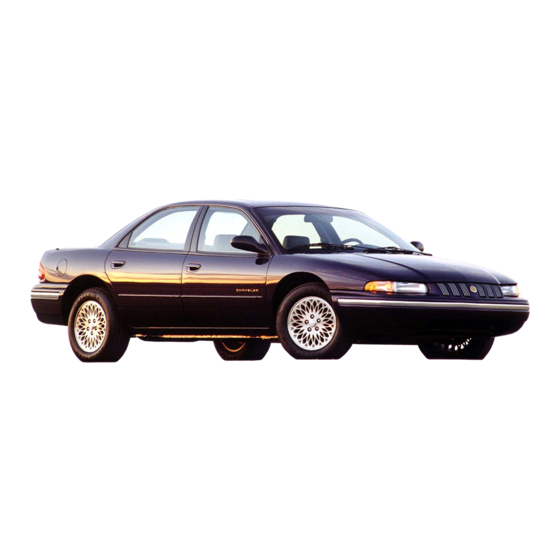
CONCORDE
INTREPID
VISION
To order the special service tools used and
illustrated, please refer to the instructions on
inside back cover.
NO PART OF THIS PUBLICATION MAY BE
REPRODUCED, STORED IN A RETRIEVAL
SYSTEM, OR TRANSMITTED, IN ANY FORM
OR BY ANY MEANS, ELECTRONIC, ME-
CHANICAL, PHOTOCOPYING, RECORDING,
OR OTHERWISE, WITHOUT THE PRIOR
WRITTEN
PERMISSION
OF
CHRYSLER
CORPORATION.
Chrysler Corporation reserves the right to make changes in design or to
make additions to or improvements in its products without imposing any ob-
ligations upon itself to install them on its products previously manufactured.
Litho in U.S.A. Copyright © 1992 Chrysler Corporation 15M0692
NEXT PAGE

Advertisement

Table of Contents
loading

Summary of Contents for Chrysler Concorde 1993

  • Page 1 PERMISSION CHRYSLER CORPORATION. Chrysler Corporation reserves the right to make changes in design or to make additions to or improvements in its products without imposing any ob- ligations upon itself to install them on its products previously manufactured. Litho in U.S.A. Copyright © 1992 Chrysler Corporation 15M0692...
  • Page 2 OEM fasteners. When re- placing fasteners, always use the same type (part number) fastener as removed. Chrysler Corporation reserves the right to change testing procedures, specifications, diagnosis, repair methods, or vehicle wiring at any time without prior notice or incurring obligation.
  • Page 3 GROUP TAB LOCATOR Introduction Lubrication and Maintenance Suspension and Driveshaft Brakes Cooling System Electrical Engines Exhaust System and Intake Manifold Frame and Bumpers Fuel System Steering Transaxle Wheels and Tires Body Components Heating and Air Conditioning Emission Control Systems Component and System Index Service Manual Comment Forms (Rear of Manual)
  • Page 5 Towing Recommendations ....5 INTRODUCTION FUEL USAGE Chrysler Corporation has compiled recommended All Chrysler Corporation engines require the use of lubrication and maintenance schedules and proce- unleaded fuel to reduce exhaust emissions. See En- dures to help reduce premature wear or failure over gine section of this group and Group 14, Fuel for fuel a broad range of operating conditions.
  • Page 6 Cooling System 3.3L..........10.74L (10.17 qts.) PARTS REQUIRING NO LUBRICATION 3.5L..........12.46L (11.80 qts.) Many components on a Chrysler Corporation vehi- Includes heater and coolant pressure bottle cle require no periodic maintenance. Some compo- Transmission ........9.4L (9.9 qts.) nents are sealed and permanently lubricated. Rubber...
  • Page 7 LUBRICATION AND MAINTENANCE 0 - 3...
  • Page 8 0 - 4 LUBRICATION AND MAINTENANCE JUMP STARTING PROCEDURE WARNING: REVIEW ALL SAFETY PRECAUTIONS AND WARNINGS IN GROUP 8A, BATTERY/START- ING/CHARGING SYSTEMS DIAGNOSTICS. DO NOT JUMP START A FROZEN BATTERY, PER- SONAL INJURY CAN RESULT. DO NOT JUMP START WHEN BATTERY INDICA- TOR DOT IS YELLOW OR BRIGHT COLOR.
  • Page 9 LUBRICATION AND MAINTENANCE 0 - 5 TO HOIST OR JACK VEHICLE SEE FIG. 2 site end of the vehicle, especially when towing over rough terrain or steep rises in the road. If necessary, remove the wheels from the lifted end of the vehicle and lower the vehicle closer to the ground, to in- crease the ground clearance at the opposite end of the vehicle.
  • Page 10 0 - 6 LUBRICATION AND MAINTENANCE REAR TOWING PROCEDURES CAUTION: Do not tow vehicle with the rear end lifted. If damage to the vehicle prevents front towing, use a flat bed towing device. CAUTION: Do not push the vehicle with another ve- hicle as damage to the bumper facia and transaxle can result.
  • Page 11 • Frequent trailer towing • Extensive idling (such as vehicle operation in stop On a Chrysler Corporation vehicle an extended and go traffic) break-in period is not required. Driving speeds of not • More than 50% of your driving is at sustained over 80-90 km/h (50-55 mph) for the first 100 km (60 high speeds during hot weather, above 32°C (90°F)
  • Page 12 (7) Start engine and inspect for leaks. (8) Stop engine and inspect oil level. ENGINE OIL FILTER SELECTING OIL FILTER Chrysler Corporation recommends a Mopar or Fig. 1 API Symbol equivalent oil filter be used when replacement is re- ENGINE OIL ADDITIVES quired.
  • Page 13 LUBRICATION AND MAINTENANCE 0 - 9 Do not operate vehicle without proper concentra- tion of recommended ethylene glycol coolant, high running temperatures and cooling system corrosion can result. The engine cooling system will develop internal pressure of 97 to 123 kPa (14 to 18 psi) at normal op- erating temperature.
  • Page 14 Capacity Chart in General Information section of this group. SELECTING ANTIFREEZE Chrysler Corporation recommends Mopar Anti- freeze/Summer Coolant, or equivalent be used to win- terize and protect cooling system. PRESSURE CAP The pressure cap must be secure for the engine cooling system to perform properly.
  • Page 15 LUBRICATION AND MAINTENANCE 0 - 11 Chrysler Corporation recommends that a PCV Chrysler Corporation recommends that only fuel valve not be cleaned. A new Mopar or equivalent purchased from a reputable retailer be used. Use PCV valve should be installed when servicing is re- high quality, unleaded gasoline to provide satisfac- quired.
  • Page 16 Inspect battery tray, hold down and terminal con- exists, replacement is required. To reduce deteriora- nections when other under hood service is performed. tion of rubber components, Chrysler Corporation rec- For proper diagnostic procedures refer to Group 8A, ommends Mopar...
  • Page 17 SELECTING AUTOMATIC TRANSAXLE FLUID TO INSPECT THE TRANSAXLE FLUID LEVEL: Chrysler Corporation recommends Mopar ATF Plus (automatic transmission fluid type 7176) be used to (1) Position the vehicle on a level surface. a1dd to or replace automatic transaxle fluid. If ATF...
  • Page 18 22, Wheels and Tires. TIRE ROTATION The Forward Cross rotation method is recom- mended for use on Chrysler Corporation vehicles (Fig. 5). Other rotation methods can be used, but may not have the benefits of the recommended method. Only the four tire rotation method can be used if the vehicle is equipped with a space saver spare tire.
  • Page 19 LUBRICATION AND MAINTENANCE 0 - 15 CHASSIS AND BODY INDEX page page Body Lubrication ......16 Steering Linkage .
  • Page 20 0 - 16 LUBRICATION AND MAINTENANCE (3) Using a wiping cloth, clean oil and dirt residue If fluid level should become low after several thou- from around power steering reservoir cap. sand kilometers (miles), fill the reservoir to level (4) Remove reservoir cap or dipstick and wipe off marks on the side of the reservoir (Fig.
  • Page 21 LUBRICATION AND MAINTENANCE 0 - 17 • Trunk lid hinges—Pivot points. catch and hood hinges when other under hood service is performed. Mopar Multi-purpose Grease or equiva- USE MOPAR LUBRIPLATE OR EQUIVALENT ON lent should be applied sparingly to all pivot and slide •...
  • Page 23 SUSPENSION AND DRIVESHAFTS 2 - 1 SUSPENSION AND DRIVESHAFTS CONTENTS page page DRIVESHAFTS ......40 GENERAL INFORMATION ....1 FRONT SUSPENSION .
  • Page 24 2 - 2 SUSPENSION AND DRIVESHAFTS...
  • Page 25 SUSPENSION AND DRIVESHAFTS 2 - 3 SUSPENSION/STEERING/DIAGNOSIS FRONT WHEEL DRIVE...
  • Page 26 2 - 4 SUSPENSION AND DRIVESHAFTS FRONT SUSPENSION FRONT SUSPENSION MAJOR COMPONENTS bolt clearance. The stud is clamped and locked into (FIG. 2) the steering knuckle leg with a clamp bolt. The ball joint used on the L.H. Platform vehicle is non-ser- STRUT ASSEMBLY viceable and if defective must be serviced as part of The front strut and suspension of the vehicle is...
  • Page 27 SUSPENSION AND DRIVESHAFTS 2 - 5...
  • Page 28 • Gas pressurized front strut must be replaced as an Chrysler Corporation be used. assembly. The strut is not serviceable. It is not neces- There are six basic factors which are the foundation sary to replace strut assemblies in pairs.
  • Page 29 SUSPENSION AND DRIVESHAFTS 2 - 7 bumper at center and jouncing each end an equal number of times. Always release bumpers at bottom of down cycle. Fig. 2 Front Wheel Toe Adjustment Fig. 3 Tie Rod Adjustment Sleeve Thread Engage- ment Fig.
  • Page 30 2 - 8 SUSPENSION AND DRIVESHAFTS STRUT DAMPER ASSEMBLY REMOVAL (1) Raise vehicle on jackstands or centered on a frame contact type hoist. See Hoisting in the Lubri- cation and Maintenance section of this manual, for the required lifting procedure to be used for this ve- hicle.
  • Page 31 SUSPENSION AND DRIVESHAFTS 2 - 9 (2) Position steering knuckle neck into strut as- sembly. CAUTION: The strut assembly to steering knuckle bolts are serrated were they go through strut as- sembly and steering knuckle. When installing bolts, turn nuts onto bolts DO NOT TURN BOLTS IN STEERING KNUCKLE.
  • Page 32 2 - 10 SUSPENSION AND DRIVESHAFTS spring isolator, spring and upper strut mount for in- dexing of the parts at assembly. (3) Position Spring Compressors, Special Tool C-4838 on the strut assembly spring (Fig. 1). Com- press coil spring until all load is removed from upper strut mount assembly.
  • Page 33 SUSPENSION AND DRIVESHAFTS 2 - 11 (8) Remove lower spring isolator from strut assem- bly lower spring seat (Fig. 6). Fig. 3 Upper Strut Mount Removal Fig. 6 Lower Spring Isolator Inspect all disassembled components for signs of abnormal wear or failure replacing any components as required.
  • Page 34 2 - 12 SUSPENSION AND DRIVESHAFTS Fig. 8 Bearing Installation Into Seat Fig. 10 Jounce Bumper Installation (4) Lower seat/bearing and dust shield onto strut as- from turning (Fig. 2), torque strut shaft nut to 94 N¼m sembly and spring. Align paint mark on seat/bearing and (70 ft.
  • Page 35 SUSPENSION AND DRIVESHAFTS 2 - 13 LOWER CONTROL ARM SERVICE The lower control arm if damaged, is serviced only as a complete component. Do not attempt to repair or straighten a broken or bent lower control arm. The only serviceable components of the lower control arm are, the pivot bushing, ball joint seal and tension strut bushing.
  • Page 36 2 - 14 SUSPENSION AND DRIVESHAFTS (7) Separate lower control arm and tension strut CAUTION: Pulling steering knuckle out from vehicle from the cradle as an assembly. Lower control arm is after releasing from ball joint can separate inner removed from cradle, by first removing pivot bushing C/V joint.
  • Page 37 SUSPENSION AND DRIVESHAFTS 2 - 15 (7) Lower vehicle so the suspension is supporting vehicles weight (control arm at design height). Torque the lower control arm pivot bushing to cradle bracket attaching bolt (Fig. 9) to 123 N¼m (90 ft. lbs.).
  • Page 38 2 - 16 SUSPENSION AND DRIVESHAFTS Fig. 12 Tightening Wheel Nuts Fig. 14 Tension Strut Bushing Installed On Tension Strut Fig. 13 Lower Control Arm Pivot Bolt Fig. 15 Tension Strut Bushing Installed In Cradle TENSION STRUT TO CRADLE BUSHING INSTALL REMOVE (1) Install lower control arm and tension strut as...
  • Page 39 SUSPENSION AND DRIVESHAFTS 2 - 17 TENSION STRUT TO LOWER CONTROL ARM BUSHING To remove tension strut to lower control arm bush- ing for replacement, the tension strut and lower con- trol arm MUST first be removed as an assembly from the vehicle.
  • Page 40 2 - 18 SUSPENSION AND DRIVESHAFTS Fig. 20 Tension Strut Installed In Lower Control Arm Fig. 22 Tightening Wheel Nuts When torquing tension strut nut, keep tension strut from turning by holding tension strut at flat using an open end wrench (Fig. 21). Fig.
  • Page 41 SUSPENSION AND DRIVESHAFTS 2 - 19 Fig. 1 Lower Control Arm Pivot Bushing Removal Fig. 3 Pivot Bushing Installed In Lower Control Arm INSTALL strut in lower control as shown in (Fig. 4), with word FRONT stamped in tension strut positioned away (1) Turn the lower control arm over in the arbor from control arm.
  • Page 42 2 - 20 SUSPENSION AND DRIVESHAFTS for the required removal procedure. up off the control arm. At this time remove the control (2) Separate the tension strut from the lower con- arm assembly from the arbor press and pull Special trol arm assembly.
  • Page 43 SUSPENSION AND DRIVESHAFTS 2 - 21 SERVICING STABILIZER BAR AND BUSHINGS The stabilizer bar interconnects the front MacPher- son strut assemblies of the vehicle and attaches to the front cradle of the vehicle (Fig. 1). Jounce and rebound movements affecting one wheel are partially transmitted to the opposite wheel to stabilize body roll.
  • Page 44 2 - 22 SUSPENSION AND DRIVESHAFTS...
  • Page 45 SUSPENSION AND DRIVESHAFTS 2 - 23 All parts are serviceable, and the stabilizer bar to cradle isolator bushings are split for easy removal and installation. The split in the stabilizer bar to crossmember bushing should be positioned toward the front of the vehicle. STABILIZER BAR ISOLATOR BUSHING SERVICE If only the stabilizer bar isolator bushings require...
  • Page 46 2 - 24 SUSPENSION AND DRIVESHAFTS CAUTION: No attempt should be made to support or lift either engine application using the intake mani- fold, or any other location on engine not specified below. 3.3 LTR ENGINE (1) Mount Fixture, Engine Support Special Tool 7137 or equivalent across engine compartment (Fig.
  • Page 47 SUSPENSION AND DRIVESHAFTS 2 - 25 Fig. 9 Front Engine Support Attachment To Generator Bracket Fig. 7 Engine Supporting Fixture Installed 3.5 Ltr. Fig. 10 Control Arm To Steering Knuckle Attachment Fig. 8 Front Engine Support Attachment To Timing Belt Housing (4) Carefully insert a pry bar between lower control arm and steering knuckle (Fig.
  • Page 48 2 - 26 SUSPENSION AND DRIVESHAFTS Fig. 14 Transmission Mount To Cradle Assembly Mounting Bolts Fig. 12 Ground Strap Fig. 15 Stabilizer Bar Isolator Bushing Attachment To Cradle (9) Position a jack stand under front of cradle and at center of transaxle to cradle assembly mount (Fig. 16).
  • Page 49 SUSPENSION AND DRIVESHAFTS 2 - 27 (10) Cradle assembly is now ready to be removed from vehicle using the following procedure. A helper will be required when removing cradle assembly from vehicle. • Loosen but do not fully remove the 2 rear cradle assembly to body attaching bolts (Fig.
  • Page 50 2 - 28 SUSPENSION AND DRIVESHAFTS Fig. 20 Stabilizer Bar Stored For Cradle Installation • Continue to raise cradle assembly and engine us- ing jack stand until the 2 front cradle assembly to body attaching bolts (Fig. 21) can be started. •...
  • Page 51 SUSPENSION AND DRIVESHAFTS 2 - 29 (8) Install lower ball joint studs into steering STEERING KNUCKLE SERVICE knuckles. Install steering knuckle to lower ball joint The front suspension knuckle (Fig. 1) provides for stud, clamp bolts and nuts into steering knuckles steering control of the vehicle.
  • Page 52 2 - 30 SUSPENSION AND DRIVESHAFTS Fig. 2 Disc Brake Caliper Mounting Fig. 4 Speed Sensor Head Removal (Typical) (4) Remove front braking disk (rotor) from hub, by pulling it straight off wheel mounting studs (Fig. 3). Fig. 5 Hub And Bearing To Stub Axle Retaining Nut Fig.
  • Page 53 SUSPENSION AND DRIVESHAFTS 2 - 31 CAUTION: If metal seal (Fig. 7) on hub and bearing assembly is seized to steering knuckle and be- comes dislodged on hub and bearing assembly dur- ing bearing removal. The hub and bearing assembly MUST not be re-used and MUST be replaced with a new hub and bearing assembly.
  • Page 54 2 - 32 SUSPENSION AND DRIVESHAFTS Fig. 11 Separating Ball Joint From Steering Knuckle Fig. 13 Control Arm To Steering Knuckle Attach- ment CAUTION: The strut assembly to steering knuckle bolts are serrated were they go through strut as- turn nuts onto bolts DO NOT TURN BOLTS IN STEER- sembly and steering knuckle.
  • Page 55 SUSPENSION AND DRIVESHAFTS 2 - 33 1993 Concorde/Intrepid/Vision Publication No. 81-270-3140 TSB 02-13-94 September 23, 1994 (4) Install hub and bearing assembly onto stub shaft steering knuckle. Install speed sensor head into steer- and into steering knuckle until squarely seated on face ing knuckle.
  • Page 56 2 - 34 SUSPENSION AND DRIVESHAFTS Fig. 20 Tighten Hub And Bearing Retaining Nut Front Disc Brake Service in the Brake Section of this service manual for caliper removal procedure. Fig. 18 Disc Brake Caliper Mounting Fig. 1 Disc Brake Caliper Mounting (4) Remove front braking disk (rotor) from hub, by pulling it straight off wheel mounting studs (Fig.
  • Page 57 SUSPENSION AND DRIVESHAFTS 2 - 35 Fig. 4 Hub And Bearing Assembly Retaining Bolts Fig. 2 Removing Braking Disc Fig. 5 Hub And Bearing Assembly Seal Fig. 3 Hub And Bearing To Stub Axle Retaining Nut CAUTION: When installing hub and bearing assem- (7) Remove hub and bearing assembly from steer- bly into steering knuckle, be careful not to damage ing knuckle, by sliding it straight out of steering...
  • Page 58 2 - 36 SUSPENSION AND DRIVESHAFTS Fig. 9 Hub And Bearing Assembly Retaining Bolts Fig. 6 Hub And Bearing Assembly Removal And Installation nut and can not be re-used. A NEW retaining nut MUST be used when assembled. (3) Install a NEW hub and bearing assembly to stub shaft retaining nut (Fig.
  • Page 59 SUSPENSION AND DRIVESHAFTS 2 - 37 1993 Concorde/Intrepid/Vision Publication No. 81-270-3140 TSB 02-13-94 September 23, 1994 Fig. 13 Tightening Wheel Nuts Fig. 11 Installing Braking Disc Fig. 14 Tighten Hub And Bearing Retaining Nut (9) Check the Toe setting on the vehicle and reset if not with in specifications.
  • Page 60 2 - 38 SUSPENSION AND DRIVESHAFTS REMOVE threads on stud are even with end of lug nut. Install Remover, Special Tool C-4150 on hub and bearing (1) Raise vehicle on jackstands or centered on a frame assembly flange and wheel stud (Fig. 3). contact type hoist.
  • Page 61 SUSPENSION AND DRIVESHAFTS 2 - 39 Fig. 4 Installing Wheel Stud Into Hub And Bearing Fig. 6 Disc Brake Caliper Mounting Fig. 7 Tightening Wheel Nuts Fig. 5 Installing Braking Disc...
  • Page 62 2 - 40 SUSPENSION AND DRIVESHAFTS DRIVESHAFTS INDEX page page Driveshaft Reconditioning Procedure ..46 Outer C/V Joint Sealing Boot ....49 General Information .
  • Page 63 SUSPENSION AND DRIVESHAFTS 2 - 41 SUSPENSION/STEERING/DIAGNOSIS FRONT WHEEL DRIVE...
  • Page 64 2 - 42 SUSPENSION AND DRIVESHAFTS SERVICE PROCEDURES (4) Remove front braking disk (rotor) from hub, by Procedures for removal and installation of drive- pulling it straight off wheel mounting studs (Fig. 2). shafts on the L.H. platform vehicles are different and somewhat easier, then those on other front wheel drive vehicles.
  • Page 65 SUSPENSION AND DRIVESHAFTS 2 - 43 Fig. 4 Hub And Bearing To Stub Axle Retaining Nut Fig. 7 Outer C/V Joint Removal From Hub and Bearing (10) Hold outer C/V joint assembly with one hand. Grasp steering knuckle with other and rotate it out and to the rear of the vehicle, until outer C/V joint clears hub and bearing assembly (Fig.
  • Page 66 2 - 44 SUSPENSION AND DRIVESHAFTS Fig. 10 Grease Applied To Inner Tripod Joint Spline Fig. 8 Inner Tripod Joint Removal From Stub Shaft joint spline with stub shaft spline on transaxle (Fig. INSTALL 11). Use a rocking motion with the inner tripod joint, to get it past the circlip on the transaxle stub shaft.
  • Page 67 SUSPENSION AND DRIVESHAFTS 2 - 45 1993 Concorde/Intrepid/Vision Publication No. 81-270-3140 TSB 02-13-94 September 23, 1994 Fig. 13 Strut Assembly To Steering Knuckle Attaching Bolts Fig. 12 Outer C/V Joint Installation Into Hub and Bearing (6) Install the top of the steering knuckle into the strut assembly.
  • Page 68 2 - 46 SUSPENSION AND DRIVESHAFTS 1993 Concorde/Intrepid/Vision Publication No. 81-270-3140 TSB 02-13-94 September 23, 1994 Fig. 17 Tightening Wheel Nuts Fig. 15 Installing Braking Disc Fig. 18 Tighten Hub And Bearing Retaining Nut If any failure of internal driveshaft components is diagnosed during a vehicle road test or disassembly of the drive shaft, the drive shaft will need to be replaced as an assembly.
  • Page 69 SUSPENSION AND DRIVESHAFTS 2 - 47 Fig. 1 L.H. Platform Driveshaft Components shaft to disengage tripod housing from transmission stub shaft. Removal in this manner will cause dam- age to inboard boots. (1) Remove the driveshaft requiring boot replace- ment from the vehicle. See Servicing Driveshaft in this section of the service manual for the required drive shaft removal procedure.
  • Page 70 2 - 48 SUSPENSION AND DRIVESHAFTS Do not hit the outer tripod bearings in an at- tempt to install spider assembly on interconnect- ing shaft. (3) Install the spider assembly to interconnecting shaft retaining snap ring into groove on end of inter- connecting shaft (Fig.
  • Page 71 SUSPENSION AND DRIVESHAFTS 2 - 49 clamp (Fig. 7). Tighten nut on crimping tool C-4975 until jaws on tool are closed completely together, face to face (Fig. 8). Fig. 9 Boot and Clamp Positioning Fig. 7 Crimping Tool Installed On Sealing Boot Clamp Fig.
  • Page 72 2 - 50 SUSPENSION AND DRIVESHAFTS and discard. Remove the sealing boot from the outer slide the replacement outer C/V joint assembly seal- C/V joint housing and slide it down the interconnecting ing boot onto the interconnecting shaft. shaft. (2) Install outer C/V joint assembly onto intercon- necting shaft.
  • Page 73 SUSPENSION AND DRIVESHAFTS 2 - 51 Fig. 4 Crimping Tool Installed On Sealing Boot Fig. 5 Sealing Boot Retaining Clamp Installed Clamp (8) Install the driveshaft requiring boot replace- ment back into the vehicle. See Servicing Driveshaft in this section of the service manual for the required drive shaft installation procedure.
  • Page 74 2 - 52 SUSPENSION AND DRIVESHAFTS REAR SUSPENSION INDEX page page General Information ..... . . 52 Rear Wheel Toe Setting Procedure .
  • Page 75 SUSPENSION AND DRIVESHAFTS 2 - 53...
  • Page 76 2 - 54 SUSPENSION AND DRIVESHAFTS 1993 Concorde/Intrepid/Vision Publication No. 81-270-3140 TSB 02-07-92 November 16, 1992 REAR WHEEL TOE SETTING PROCEDURE Rear Wheel alignment adjustments can only be made for the Toe In setting on the L.H. platform vehicles. Toe is measured in degrees or inches and is the distance the front edges of the tires are closer (or farther apart) than the rear edges.
  • Page 77 SUSPENSION AND DRIVESHAFTS 2 - 55 Fig. 2 Brake Hose Bracket And Tube Fig. 5 Attachment Link To Stabilizer Bar Attaching speed sensor cable attached damage to speed (8) Loosen and fully remove, the rear spindle to sensor cable may occur. strut assembly pinch bolt (Fig.
  • Page 78 2 - 56 SUSPENSION AND DRIVESHAFTS Fig. 7 Center Punch Installed In Spindle Fig. 9 Spindle Assembly Removed From Strut Fig. 8 Removing Spindle From Strut Assembly INSPECTION Inspect for evidence of fluid leakage from upper end of reservoir. (Actual leakage will be a stream of fluid running down and leaking off lower end).
  • Page 79 SUSPENSION AND DRIVESHAFTS 2 - 57 Fig. 14 Brake Hose Bracket And Tube Nut Fig. 11 Lateral Links To Spindle Attaching Bolt (8) If vehicle has rear drum brakes, brake system will require bleeding. Refer to Bleeding Brake Sys- tem in the Service Adjustments Section of Group 5 Brakes in this service manual.
  • Page 80 2 - 58 SUSPENSION AND DRIVESHAFTS • Dust shield • Mount assembly • Jounce Bumper • Lower Spring Isolator • Shaft Nut (1) Remove strut assembly requiring service from the vehicle. Refer to Strut Assembly Removal in Ser- vicing Rear Struts, in this section of the service man- ual.
  • Page 81 SUSPENSION AND DRIVESHAFTS 2 - 59 Fig. 6 Lower Spring Isolator Fig. 4 Coil Spring Remove And Replace Fig. 7 Jounce Bumper Installed Into Dust Shield Fig. 5 Plate, Dust Shield And Jounce Bumper Remove And Replace (5) Install the upper strut mount assembly onto the strut shaft, aligning paint marks (Fig.
  • Page 82 2 - 60 SUSPENSION AND DRIVESHAFTS (8) Install the strut assembly back into the vehicle. Refer to Strut Assembly Removal in Servicing Rear Struts in this section of the service manual. (9) Check and reset rear wheel TOE to specifications if required.
  • Page 83 SUSPENSION AND DRIVESHAFTS 2 - 61 the rear spindle (Fig. 6). Then remove the adapter, disc shield, park brake shoes and park brake cable as an assembly from spindle. Fig. 3 Rear Hub And Bearing Retaining Nut and Washer Removal Fig.
  • Page 84 2 - 62 SUSPENSION AND DRIVESHAFTS Fig. 8 Trailing Arm To Spindle Bracket Bolt Fig. 11 Center Punch Installed In Spindle Fig. 9 Lateral Links To Spindle Attaching Bolt Fig. 12 Removing Spindle From Strut Assembly Then remove center punch from hole in spindle. In- stall spindle to strut assembly pinch bolt into spindle (Fig.
  • Page 85 SUSPENSION AND DRIVESHAFTS 2 - 63 (2) Install the lateral links to spindle attaching bolt (Fig. 14). Torque the lateral links to spindle at- taching bolt to 140 N¼m (105 ft. lbs.). Fig. 16 Speed Sensor Routing Tube And Bracket Fig.
  • Page 86 2 - 64 SUSPENSION AND DRIVESHAFTS (7) If vehicle is equipped with Anti-Lock brakes. wheel cylinder tube nut to 17 N¼m (145 in. lbs.). Install the speed sensor head into the rear disc brake Torque the brake hose bracket to support plate bolt adapter (Fig.
  • Page 87 SUSPENSION AND DRIVESHAFTS 2 - 65 ent. The performance suspension crossmember is iden- tified by a hole in the crossmember. Hole is located on left side of crossmember, on rear vertical wall (Fig. 1). If crossmember is replaced be sure the correct crossmember is installed or handling of the ve- hicle will be adversely affected.
  • Page 88 2 - 66 SUSPENSION AND DRIVESHAFTS (4) Remove the 4 crossmember to frame rail at- taching bolts (Fig. 1). Fig. 3 Crossmember To Frame Rail Attaching Bolts Fig. 1 Crossmember To Frame Rail Attaching Bolts (5) Remove fuel tank. Refer to Group 14 Fuel, in this service manual for the required fuel tank re- moval procedure.
  • Page 89 SUSPENSION AND DRIVESHAFTS 2 - 67 (4) Position crossmember on frame rails and install the 4 crossmember to frame rail attaching bolts (Fig. 1). Torque the crossmember to frame rail attaching bolts to 95 N¼m (70 ft. lbs.). (5) Remove transmission jack supporting fuel tank. (6) Install wheel and tire assembly on vehicle.
  • Page 90 2 - 68 SUSPENSION AND DRIVESHAFTS Fig. 2 Lateral Link Attachment To Spindle Fig. 4 Tightening Wheel Nuts (4) Remove the nut and bolt attaching the left lat- (5) Lower vehicle to the ground. (6) Check and reset rear wheel TOE to specifica- eral links to the rear crossmember (Fig.
  • Page 91 SUSPENSION AND DRIVESHAFTS 2 - 69 (5) Remove the 4 crossmember to frame rail attach- ing bolts (Fig. 6). (6) Lower rear crossmember far enough so right lateral links to crossmember attaching bolt will clear fuel tank. Fig. 7 Right Lateral Links To Crossmember Bolt 6).
  • Page 92 2 - 70 SUSPENSION AND DRIVESHAFTS SPECIFICATIONS ALIGNMENT SPECIFICATIONS AT CURB HEIGHT...
  • Page 93 SUSPENSION AND DRIVESHAFTS 2 - 71 1993 Concorde/Intrepid/Vision Publication No. 81-270-3140 TSB 02-17-94 November 18,1994 REAR SUSPENSION TORQUE FRONT SUSPENSION TORQUE SPECIFICATIONS SPECIFICATIONS...
  • Page 95: Table Of Contents

    BRAKES 5 - 1 BRAKES CONTENTS page page ANTI-LOCK BRAKE SYSTEM—TEVES MARK MASTER CYLINDER ..... 69 IV SYSTEM ......75 PARKING BRAKES .
  • Page 96 5 - 2 BRAKES CAUTION: Caliper pistons, boots and seals for the different caliper assemblies used on the front and rear disc brake assemblies are not interchangeable. Misusage could result in a complete brake system failure. Be sure that the parts are replaced with the correct replacement parts, refer to the parts book for the type and model year of the vehicle being worked on.
  • Page 97 BRAKES 5 - 3 Fig. 3 Proper Nut Thread Size And Tube Routing (ABS Equipped)
  • Page 98 5 - 4 BRAKES SERVICE ADJUSTMENTS INDEX page page Adjusting Rear Service Brakes ....4 Road Wheel Stud Nut Tightening ... . . 6 Bleeding Brake System .
  • Page 99 BRAKES 5 - 5 PRESSURE BLEEDING Before removing the master cylinder cover, wipe it clean to prevent dirt and other foreign matter from dropping into the master cylinder. CAUTION: Use bleeder tank Special Tool C-3496-B or equivalent, with Snap-On adapter BB400-9A or equivalent (Fig.
  • Page 100: System

    5 - 6 BRAKES volume of brake fluid when bleeding the brakes. This Enough fluid has not passed through the system to will ensure all the air is bled from the brakes hy- expel all the trapped air. Be sure to monitor the fluid draulic system.
  • Page 101 BRAKES 5 - 7 Fig. 5 Tightening Wheel Nuts Fig. 1 Anti-Lock Equipped Vehicle Flex Hoses BRAKE HOSE AND TUBING the Banjo connector to the caliper assembly. Then attach the remaining hose end bracket to the vehicle INSPECTION OF BRAKE HOSE AND TUBING frame to minimize hose twisting.
  • Page 102 5 - 8 BRAKES areas. All tubes should be properly attached with recommended retaining clips. Care must be taken during the removal and replace- ment of components on a vehicle equipped with Anti- Lock brakes. To avoid damage to the flexible stainless steel hoses between the master cylinder and Anti-Lock hydraulic control unit.
  • Page 103 BRAKES 5 - 9 Fig. 6 Stop Lamp Switch Screw in the feed screw of the yoke assembly until the adaptor has seated squarely on the surface of the bar assembly (Fig. 5). This process has created the (metric) ISO tubing flare. Fig.
  • Page 104 5 - 10 BRAKES 1993 Concorde/Intrepid/Vision Publication No. 81-270-3140 TSB 05-12-93 August 13, 1993 BRAKE SYSTEM DIAGNOSTICS...
  • Page 105 BRAKES 5 - 11 BRAKE SYSTEM DIAGNOSTICS...
  • Page 106 5 - 12 BRAKES BRAKE SYSTEM DIAGNOSTICS...
  • Page 107 BRAKES 5 - 13 BRAKE SYSTEM DIAGNOSTICS BRAKE SYSTEM DIAGNOSTICS...
  • Page 108 5 - 14 BRAKES REAR WHEEL DRUM BRAKES INDEX page page Brake Drum Refacing ..... 18 Description ......14 Brake Shoe Assemblies .
  • Page 109 BRAKES 5 - 15 REMOVE (1) Remove rear hub and bearing assembly dust cap (Fig 4). Then remove cotter pin and nut lock from spindle. (2) Remove the rear hub and bearing assembly re- taining nut and washer (Fig. 5). Remove rear hub and bearing assembly from spindle.
  • Page 110 5 - 16 BRAKES (4) Rotate the automatic adjuster screw assembly so (6) Remove both lower brake shoe assembly to an- that each shoe assembly moves out far enough to be chor plate springs (Fig. 9). free from the wheel cylinder boots (Fig. 7). Fig.
  • Page 111 BRAKES 5 - 17 Fig. 13 Automatic Adjuster Lever or equivalent to the threads of the self adjuster. Re- place adjusting screw if corroded. If old springs have overheated or are damaged, re- place them. Overheating indication is distorted end coils.
  • Page 112 5 - 18 BRAKES ing on vehicle. Be sure automatic adjuster ends are above extruded pins in web of brake shoes as shown in (Fig. 16). Fig. 17 Tightening Wheel Nuts (15) Road test vehicle. The automatic adjuster will continue the brake adjustment during the road test Fig.
  • Page 113 BRAKES 5 - 19 WHEEL CYLINDERS INDEX page page General Information ..... . . 19 Service Procedures ..... . . 19 Installing Wheel Cylinders .
  • Page 114 5 - 20 BRAKES Fig. 3 Rear Wheel Cylinder ASSEMBLING WHEEL CYLINDERS (5) Install rear brake drum onto rear hub. (6) Install the wheel and tire assembly. Tighten Before assembling the pistons and new cups in the the wheel mounting stud nuts in proper sequence wheel cylinders, dip them in clean brake fluid.
  • Page 115: Brake Support Assembly

    BRAKES 5 - 21 BRAKE SUPPORT ASSEMBLY REMOVAL (1) Remove rear tire and wheel assembly from ve- hicle. (2) Remove rear hub and bearing assembly dust cap (Fig 5). Then remove cotter pin and nut lock from spindle. Fig. 7 Remove or Install Automatic Adjuster Lever Fig.
  • Page 116 5 - 22 BRAKES INSTALLATION (1) Insert parking brake cable and housing end fitting into brake support plate. (2) Install support plate and gasket on rear suspen- sion knuckle casting. Torque support plate to knuckle casting attaching bolts to 115 N¼m (85 ft. lbs). (3) Attach cable to parking brake lever.
  • Page 117 BRAKES 5 - 23 HYDRAULIC SYSTEM CONTROL VALVES INDEX page page ABS Brake Proportioning Valve Operation ..23 Non-ABS Proportioning Unit Operation ..23 General Information ..... . . 23 Testing ABS Proportioning Valves .
  • Page 118 5 - 24 BRAKES Each rear brake circuit has its own screw-in propor- HYDRAULIC SYSTEM SERVICE PROCEDURES tioning valve which is attached to the rear brake outlet BRAKE WARNING SYSTEM ports of the hydraulic control unit (HCU). The valves limit brake pressure to rear brakes after a certain CHECKING BRAKE WARNING SWITCH UNIT pressure is reached.
  • Page 119 BRAKES 5 - 25 To test the proportioning valve when the right rear wheel slides first, leave the front brakes connected to the valve, and proceed as follows: (1) Install one gauge and (TEE) of set C-4007-A between the brake line from the master cylinder sec- ondary port and the brake valve assembly (Fig.
  • Page 120 5 - 26 BRAKES lowing chart, replace the valve. See (Fig. 4) for pro- portioning valve identification. Fig. 4 ABS PROPORTIONING VALVE IDENTIFICATION PROPORTIONING VALVE PRESSURES NON-ABS BRAKES PROPORTIONING VALVE PRESSURES ABS-BRAKES...
  • Page 121: Front Disc Brakes

    BRAKES 5 - 27 FRONT DISC BRAKES INDEX page page General Information ..... . . 27 Shoe and Lining Wear .
  • Page 122 5 - 28 BRAKES Fig. 2 Disc Brake Caliper Mounting (Exploded View) As lining wears, master cylinder reservoir brake fluid level will go down. If brake fluid has been added to the reservoir, reservoir overflow may occur when the piston is pushed back into the new lining position.
  • Page 123 BRAKES 5 - 29 SERVICE PRECAUTIONS SURE TO YOURSELF AND OTHERS. FOLLOW ALL RECOMMENDED PRACTICES PRE- WARNING: DUST AND DIRT ON BRAKE PARTS SCRIBED BY THE OCCUPATIONAL SAFETY AND GENERATED DURING THE NORMAL USE AND HEALTH ADMINISTRATION AND THE ENVIRONMEN- WEAR OF MOTOR VEHICLE BRAKE SYSTEMS CAN TAL PROTECTION AGENCY.
  • Page 124: Kelsey Hayes Double Pin Caliper Assembly

    5 - 30 BRAKES KELSEY HAYES DOUBLE PIN CALIPER ASSEMBLY INDEX page page Brake Shoe Service Procedures ... . . 30 Disc Brake Caliper Service ....32 Caliper Assembly Inspection .
  • Page 125 BRAKES 5 - 31 Fig. 6 Removing Inboard Brake Shoe (3) Install the front braking disc (rotor) on the hub, making sure it is squarely seated on face of hub (Fig. (4) Remove the protective paper from the noise sup- pression gasket on both the inner and outer brake shoe Fig.
  • Page 126 5 - 32 BRAKES Fig. 8 Installing Inboard Brake Shoe Assembly Fig. 10 Installing Caliper Assembly On Steering Knuckle And Rotor Fig. 9 Installing Outboard Brake Shoe Assembly (7) Carefully position caliper and brake shoe assem- blies over braking disc (rotor) using the reversed re- quired removal procedure (Fig.
  • Page 127 BRAKES 5 - 33 Plug brake tube and remove piston from opposite caliper. Using the same process as above for the first piston removal. WARNING: UNDER NO CONDITION SHOULD AIR PRESSURE BE USED TO REMOVE PISTON FROM CALIPER BORE. PERSONAL INJURY COULD RE- SULT FROM SUCH A PRACTICE.
  • Page 128 5 - 34 BRAKES fluid. After honing the bore, carefully clean the seal and boot grooves with a stiff non-metallic rotary brush. Use extreme care in cleaning the caliper after honing. Remove all dirt and grit by flushing the caliper with brake fluid; wipe dry with a clean, lint free cloth and then clean a second time.
  • Page 129 BRAKES 5 - 35 Fig. 4 Folded Caliper Guide Pin Bushing Fig. 2 Pushing Piston into Bore (7) Using a hammer and Installer Piston Caliper Boot, Special Tool C-4689 and Handle, Special Tool C-4171, drive boot into counterbore of the caliper (Fig. Fig.
  • Page 130 5 - 36 BRAKES Fig. 7 Installing Caliper Sleeves Fig. 6 Bushing Correctly Installed In Caliper seal grove (Fig. 8). Be sure the other end of the bush- ing did not come out of the seal grove in the sleeve. (4) When the sleeve is seated properly into the bushing.
  • Page 131 BRAKES 5 - 37 REAR DISC BRAKES INDEX page page Assembling Rear Disc Brake Caliper ..43 General Information ..... . . 37 Caliper Assembly Inspection .
  • Page 132 5 - 38 BRAKES is returned to its original position on the wheel of (2) Remove rear wheel and tire assemblies from the vehicle from which it was removed. (See Brake vehicle. Shoe Installation). (3) Remove the 2 caliper assembly to adapter guide pin bolts (Fig.
  • Page 133 BRAKES 5 - 39 Fig. 5 Removing Outboard Shoe Fig. 3 Storing Caliper Fig. 6 Removing Inboard Shoe Check the caliper dust boot and caliper pin bush- ings to determine if they are in good condition. Re- place if they are damaged, dry, or found to be brittle. Refer to Cleaning And Inspection Of Brake Caliper.
  • Page 134 5 - 40 BRAKES Fig. 8 Installing Inboard Brake Shoe Assembly CAUTION: Use care when installing the caliper as- sembly onto the adapter. So the seal on the caliper sealed for life guide pin bushings do not get damaged by the mounting bosses. Fig.
  • Page 135 BRAKES 5 - 41 WARNING: UNDER NO CONDITION SHOULD AIR PRESSURE BE USED TO REMOVE PISTON FROM CALIPER BORE. PERSONAL INJURY COULD RE- SULT FROM SUCH A PRACTICE. (4) Disconnect brake flexible hose from the caliper. To disassemble, mount caliper assembly in a vise equipped with protective jaws.
  • Page 136 5 - 42 BRAKES Fig. 2 Removing Piston Seal Fig. 4 Removing Bushings From Caliper Fig. 3 Removing Inner Sleeve From Bushing body. (Whenever a caliper has been disassembled, Fig. 5 Honing Piston Bore a new boot and seal must be installed at assem- If the bore does not clean up within this specification, bly).
  • Page 137 BRAKES 5 - 43 caliper with brake fluid; wipe dry with a clean, lint free cloth and then clean a second time. ASSEMBLING REAR DISC BRAKE CALIPER (1) Clamp caliper in vise (with protective caps on vise jaws). CAUTION: Excessive vise pressure will cause bore distortion and binding of piston.
  • Page 138 5 - 44 BRAKES Fig. 9 Folded Caliper Guide Pin Bushing Fig. 11 Bushing Correctly Installed In Caliper Fig. 10 Installing Caliper Guide Pin Sleeve Bushings (1) Install the sleeve into one end of the bushing until the seal area of the bushing is past the seal groove in the sleeve (Fig.
  • Page 139 BRAKES 5 - 45 to 33 N¼m (24 ft. lbs.). New seal washers MUST always be used when installing brake hose to caliper. (8) Bleed the brake system (see Bleeding Brake System). Pump the brake pedal several times to be sure that the vehicle has a firm pedal, before the vehicle is moved or driven.
  • Page 140 5 - 46 BRAKES BRAKE DISC (ROTOR) INDEX page page Braking Disc Removal ..... 47 Installing Braking Disc ..... 47 General Information .
  • Page 141 BRAKES 5 - 47 Fig. 4 Index Braking Disc and Wheel Stud Fig. 2 Marking Braking Disc and Wheel Stud If runout is not within specifications. Install a new knuckle. Position stem so it contacts hub face near braking disc or reface disc, being careful to remove outer diameter (Fig.
  • Page 142 5 - 48 BRAKES Fig. 5 Checking Disc for Thickness REFINISHING BRAKING DISC Fig. 6 Refacing Braking Disc REFACING BRAKING DISC Refacing of the braking disc is not required each time the shoe assemblies are replaced. If the braking disc surface is deeply scored or warped or there is a complaint of brake roughness or brake pedal pulsation the rotor should be resurfaced or refaced (Figs.
  • Page 143 BRAKES 5 - 49 1993 Concorde/Intrepid/Vision Publication No. 81-270-3140 TSB 05-12-94 June 10, 1994 Fig. 8 Front Braking Disc Minimum Thickness Fig. 9 Rear Braking Disc Minimum Thickness Markings Markings thickness markings may be located on the disc as the braking disc (Fig. 9). The thickness markings may be located on the disc as shown in (Fig.
  • Page 144 5 - 50 BRAKES PARKING BRAKES INDEX page page Front Park Brake Cable Service ... . . 54 Parking Brake Shoe Service with Rear Disc General Information ..... . . 50 Brakes .
  • Page 145 BRAKES 5 - 51...
  • Page 146 5 - 52 BRAKES SERVICE PROCEDURES ADJUSTING PARKING BRAKE The parking brake foot lever assembly used on all L.H. platform vehicles, with and without rear disc brakes contains a self adjuster for the cable system. Routine parking brake cable adjustment on all L.H. platform vehicles is not required.
  • Page 147 BRAKES 5 - 53 Fig. 5 Park Brake Cable Routing In Pedal Assembly Note: The parking brake pedal must be in the fully released position when releasing self ad- juster. Using a pair of pliers, firmly grasp lock pin previ- ously installed in park brake mechanism.
  • Page 148 5 - 54 BRAKES REPLACE (1) Install park brake cable assembly, through cable mounting in park brake pedal mechanism. (2) Align park brake cable slug with attaching hole on park brake assembly (Fig. 7). Install park brake cable into cable attaching hole in park brake assembly, and rotate cable into place.
  • Page 149 BRAKES 5 - 55 (3) Remove upper center console cover from vehicle (7) Fold back carpeting to expose front park brake if equipped. Refer to Group 23 Body in this service cable and routing clips. Note: The throttle pedal manual for required procedure to remove center con- and bracket have to be removed from the dash sole.
  • Page 150 5 - 56 BRAKES (2) Remove front park brake cable from park brake cable equalizer (Fig. 14). Fig. 16 Front Park Brake Cable Routing And Clipping Fig. 14 Front Park Brake Cable Connection At Equalizer (3) Remove the front park brake cable to reaction bracket retaining clip, by prying it off cable using a screwdriver (Fig.
  • Page 151 BRAKES 5 - 57 Fig. 18 Park Brake Cable Retaining Clip Fig. 20 Park Brake Cable Installed On Pedal Assembly Fig. 19 Park Brake Cable Removal From Park Brake Mechanism Fig. 21 Park Brake Cable Installed In Mechanism REPLACE (6) Route front park brake cable along floor of ve- (1) Install park brake cable assembly, through ca- hicle.
  • Page 152 5 - 58 BRAKES Fig. 24 Front Park Brake Routing And Clipping Locations Fig. 22 Park Brake Pedal Mechanism Fig. 25 Correct Park Brake Cable Routing At Pedal Assembly (3) Install drivers side cowl kick molding (Fig. 27). Install drivers side door opening sill molding (Fig. 27).
  • Page 153 BRAKES 5 - 59 Fig. 28 Park Brake Equalizer And Cover (2) Install drivers side cowl area kick molding back in vehicle . Install drivers side door opening sill mold- ing (Fig. 27). (3) Install lower dash panel assembly back in ve- hicle.
  • Page 154 5 - 60 BRAKES Fig. 3 Park Brake Cable Routing Clip Locations (5) Remove upper center console cover from vehicle. Refer to group 23 Body in this service manual for required procedure to remove center console. (6) Remove rear console mounting bracket (Fig. 4) from park brake cable reaction bracket.
  • Page 155 BRAKES 5 - 61 retaining tabs on end of park brake cable housing. Using a screw driver, press on end of park brake cable housing to remove cable from floor pan of vehicle. Fig. 6 Park Brake Equalizer Bracket Fig. 5 Park Brake Cable Removal From Floor Pan Note: Do not remove the second rear park brake cable from the equalizer.
  • Page 156 5 - 62 BRAKES Fig. 8 Park Brake Cable Routing Clip Locations Fig. 10 Park Brake Equalizer And Cover (10) Fold rear passenger compartment carpeting back into position on floor pan of vehicle. (11) Install both lower rear door opening sill mold- ings.
  • Page 157 BRAKES 5 - 63 lation Parking Brake Shoes in this section of the ser- vice manual for the parking brake shoe assembly removal procedure. (4) Disconnect park brake cable from park brake actuator lever (Fig. 1). Fig. 3 Park Brake Cable Routing Clip Locations (8) Remove upper center console cover from vehicle.
  • Page 158 5 - 64 BRAKES retaining tabs on end of park brake cable housing. Using a screw driver, press on end of park brake cable housing to remove cable from floor pan of vehicle. Fig. 6 Park Brake Equalizer Bracket Fig. 5 Park Brake Cable Removal From Floor Pan Note: Do not remove the second rear park brake cable from the equalizer.
  • Page 159 BRAKES 5 - 65 (6) Install rear braking disc (rotor) on the rear hub assembly. Install rear disc brake caliper assembly on adapter. (7) Install rear tire and wheel assembly on vehicle. 5 PASSENGER MODELS (8) Install upper center console cover assembly back in vehicle.
  • Page 160 5 - 66 BRAKES (18) When repairs are complete, adjust rear brakes before adjusting parking brake. See parking brake adjustment procedure in this section of the ser- vice manual for complete parking brake adjust- ment procedure. On drum-in-hat type rear disc brakes adjust brake shoe diameter to 171.5 mm (6.75 in.).
  • Page 161 BRAKES 5 - 67 Fig. 4 Removing Shoe and Upper Spring Fig. 6 Installing Upper Spring Fig. 5 Removing Front Holddown Clip And Shoe Fig. 7 Installing Lower Spring (4) Install lower parking brake, shoe to shoe re- (9) Install hub and bearing assembly, thrust turn spring (Fig.
  • Page 162 5 - 68 BRAKES Fig. 8 Installing Adjuster Assembly Fig. 9 Installing Rear Parking Brake Shoe Hold- Down Clip (14) Tighten wheel stud nuts to 129 N¼m (95 ft- .lbs.).
  • Page 163 BRAKES 5 - 69 MASTER CYLINDER INDEX page page Brake Fluid Level Sensor ....69 Master Cylinder Service Procedures ..69 General Information .
  • Page 164 5 - 70 BRAKES (2) Remove 2 nuts (Fig. 3) attaching master cylinder housing to power brake booster unit. Fig. 5 Removing Reservoir (8) Lubricate brake fluid reservoir mounting area with clean brake fluid. Place reservoir in position over Fig. 3 Master Cylinder Mounting grommets.
  • Page 165 BRAKES 5 - 71 Remove bleeding tubes from cylinder, plug outlets and install caps. Remove master cylinder from vise and install on power brake vacuum booster. It is not necessary to bleed the entire hydraulic system after replacing the master cylinder, pro- viding that the master cylinder has been bled and filled upon installation.
  • Page 166: Power Brakes

    5 - 72 BRAKES POWER BRAKES GENERAL INFORMATION The purpose of the vacuum operated power brake booster. Is to reduce the amount of force applied to the brake pedal by the drivers foot. To obtain the required hydraulic pressure in the brake system to stop the vehicle.
  • Page 167 BRAKES 5 - 73 Fig. 3 Master Cylinder Mounting (7) From under instrument panel, position a small screwdriver between the center tang on the power brake booster input rod to brake pedal pin retaining clip. (8) Rotate screwdriver enough to allow retainer clip Fig.
  • Page 168: Wheel Bearings

    5 - 74 BRAKES WHEEL BEARINGS FRONT WHEEL BEARINGS (2) Remove the rear hub and bearing assembly re- taining nut and washer (Fig. 2). Remove rear hub Front wheel drive vehicles are equipped with per- and bearing assembly from spindle. manently sealed front wheel bearings.
  • Page 169 ANTI-LOCK BRAKE SYSTEM 5 - 75 ANTI-LOCK BRAKE SYSTEM—TEVES MARK IV SYSTEM INDEX page page ABS Brake System Diagnosis ....88 Hydraulic Circuits and Valve Operation .
  • Page 170 5 - 76 ANTI-LOCK BRAKE SYSTEM hydraulic pressure at each wheel brake. Depending The Pedal Travel Sensor (PTS) (Fig. 2) is a Linear on signals generated by the wheel speed sensors Variable Displacement Transducer with seven steps (WSS) at each wheel and received at the Controller which provide brake pedal position information to Anti-Lock Brake (CAB).
  • Page 171 ANTI-LOCK BRAKE SYSTEM 5 - 77 relief valves are needed because the pump can supply more volume than the system requires. The pump/motor assembly (Fig. 4) consists of an electric motor with a rotation sensor and a dual pis- ton pump. The motor shaft inside the pump is de- signed as a cam in order to drive both pistons.
  • Page 172 5 - 78 ANTI-LOCK BRAKE SYSTEM of a free rolling wheel at a given vehicle speed. This slip may result in some tire chirping, depending on the road surface. This sound should not be inter- preted as total wheel lock-up. Complete wheel lock up normally leaves black tire marks on dry pavement.
  • Page 173 ANTI-LOCK BRAKE SYSTEM 5 - 79 • Valve Fault (8/10) DIAGNOSTIC MODE • FLS 2 Not processable To enter diagnostic mode, vehicle must be below 10 • Pressure Switch/Brake Switch Circuits (Disables MPH. If vehicle speed is not below 10 MPH a no re- sponse message is displayed by the DRB II scan tool.
  • Page 174 5 - 80 ANTI-LOCK BRAKE SYSTEM BRAKE WARNING LAMP block assembly, the pump/motor assembly, and a The red BRAKE Warning Lamp is located in the fluid reservoir with a fluid level switch. Instrument Panel. It can be activated in several ways.
  • Page 175 ANTI-LOCK BRAKE SYSTEM 5 - 81 Control (Isolation) valves and a pressure switch. The PROPORTIONING VALVES valves are spring loaded in the open position. During Two Proportioning Valves (Fig. 2 and 3) are used traction control operation the traction control valves in the system, one for each rear brake hydraulic cir- are closed by the (CAB).
  • Page 176 5 - 82 ANTI-LOCK BRAKE SYSTEM produce inaccurate wheel speed signals. However, the system will continue to function correctly when using the mini-spare. Fig. 4 Wheel Speed Sensors Fig. 1 Controller Anti-Lock Brakes part label. The ABS and Traction Control controller will have a blue part label.
  • Page 177 ANTI-LOCK BRAKE SYSTEM 5 - 83 • during Anti-Lock stop and traction control opera- • Pump/Motor Sensor Signal • Diagnostic Communication (C2D) tion. • Monitor the system for proper operation. • Fluid Level Switch #2 • Provide communication to the DRB II while in di- •...
  • Page 178 5 - 84 ANTI-LOCK BRAKE SYSTEM HYDRAULIC CIRCUITS AND VALVE OPERATION Through the following operation descriptions and diagrams. The function of the various hydraulic con- trol valves in the ABS system will be described. The fluid control valves mentioned below, control the flow of pressurized brake fluid to the wheel brakes during the different modes of Anti-Lock braking.
  • Page 179 ANTI-LOCK BRAKE SYSTEM 5 - 85 Fig. 2 Baseline Brakes - Hydraulic Control Fig. 3 Pressure Hold - Hydraulic Control...
  • Page 180 5 - 86 ANTI-LOCK BRAKE SYSTEM Fig. 4 Pressure Decay - Hydraulic Control ABS BRAKING-PRESSURE DECAY TRACTION CONTROL-PRESSURE BUILD If the wheel locking tendency continues, the (CAB) If a wheel speed sensor indicates a wheel spin releases the pressure by opening the normally closed (traction loss) tendency and Traction Control func- outlet valve (Fig.
  • Page 181 ANTI-LOCK BRAKE SYSTEM 5 - 87 Fig. 5 Pressure Build - Hydraulic Control Fig. 6 Traction Control Pressure Build - Hydraulic Control...
  • Page 182 5 - 88 ANTI-LOCK BRAKE SYSTEM Fig. 7 Traction Control Pressure Hold - Hydraulic Control TRACTION CONTROL-PRESSURE HOLD CAUTION: REVIEW THIS ENTIRE SECTION PRIOR As soon as the traction loss at the spinning wheel TO PERFORMING ANY MECHANICAL WORK ON A has been braked down to acceptable limits.
  • Page 183 ANTI-LOCK BRAKE SYSTEM 5 - 89 Fig. 8 Traction Control Pressure Decay - Hydraulic Control • WSS—Wheel Speed Sensor Diagnosis of conditions which are obviously me- chanical in nature. Such as brake noise, brake pulsa- ABS COMPUTER SYSTEM SERVICE PRECAUTIONS tion, lack of power assist, turning on of the Red The ABS system uses an electronic control module, Brake Warning Lamp or vehicle vibration during...
  • Page 184 5 - 90 ANTI-LOCK BRAKE SYSTEM dicate reduced braking ability. The following WHEEL SPEED SENSOR CABLES procedure should be used to test drive an ABS Proper installation of the Wheel Speed Sensor Ca- complaint vehicle. bles is critical to continued system operation. Be sure Before test driving a brake complaint vehicle, note that cables are installed, routed and clipped properly.
  • Page 185 ANTI-LOCK BRAKE SYSTEM 5 - 91 (2) Main Relay. If the relay fails to make the recent fault was stored is also displayed. Most func- ground circuit connection or is an intermittent tions of the (CAB) and ABS system can be accessed ground.
  • Page 186 5 - 92 ANTI-LOCK BRAKE SYSTEM CHECKING BRAKE FLUID LEVEL (1) Connect pressure bleeding equipment to master cylinder. Refer to Bleeding Brake System in the Ser- CAUTION: Only use brake fluid conforming to DOT 3 vice Adjustment section of this service manual. specifications, such as Mopar or Equivalent.
  • Page 187 ANTI-LOCK BRAKE SYSTEM 5 - 93 (3) Disconnect the pump motor and fluid level sen- sor electrical connectors from the (HCU) (Fig. 2). Fig. 4 (CAB) Connector Removal From (CAB) (6) Disconnect the 2 brake tubes from the propor- tioning valves (Fig. 5) located on the bottom of the (HCU).
  • Page 188 5 - 94 ANTI-LOCK BRAKE SYSTEM fender mounting bolt (Fig. 7). Torque the 2 (HCU) bracket to frame rail attaching bolts to 19 N¼m (14 ft. lbs.). The torque bracket to inner fender bolt to 2 N¼m (18 in. lbs.). (2) Connect the 2 brake fluid supply tubes from the master cylinder onto the inlet ports of the (HCU) (Fig.
  • Page 189 ANTI-LOCK BRAKE SYSTEM 5 - 95 connector to the (CAB) using the following proce- dure. Install connector onto (CAB) with the connector pins located in latch first (Fig. 11). Then rotate rear of connector down onto (CAB) until fully seated onto connector pins on (CAB) (Fig.
  • Page 190 5 - 96 ANTI-LOCK BRAKE SYSTEM HYDRAULIC CONTROL UNIT FLUID RESERVOIR (FLS2) The reservoir at the H.C.U. (Fig. 1) includes the (FLS2) fluid level switch. This reservoir is connected to the master cylinder reservoir by a low pressure hydraulic tube. Fig.
  • Page 191 ANTI-LOCK BRAKE SYSTEM 5 - 97 REMOVE (1) Pump the brake pedal approximately 20 times to evacuate all stored vacuum from the vacuum booster. (2) Remove the wiring harness electrical connector (Fig. 1) from the end of the pedal travel sensor. (3) Using a small screwdriver, lift pedal travel sen- sor retaining ring from notch (Fig.
  • Page 192 5 - 98 ANTI-LOCK BRAKE SYSTEM If the master cylinder or the power booster need to be serviced or replaced. Refer to Master Cylinder or Power Brake Service section in this group of the service man- ual. After servicing the master cylinder or power booster.
  • Page 193 ANTI-LOCK BRAKE SYSTEM 5 - 99 (2) Install (HCU) assembly back in the vehicle. Refer to Hydraulic Control Unit Installation, in this section of the service manual for the required installation procedure. (3) Install brake tube on proportioning valve. Tighten tube nut to 15 N¼m (11 ft. lbs.) torque. (4) Bleed the air from brake hydraulic system.
  • Page 194 5 - 100 ANTI-LOCK BRAKE SYSTEM (5) Install the left front tire and wheel assembly REMOVE on vehicle. Install the wheel and tire assembly. (1) Hold the relays with one hand, and pull strait Tighten the wheel mounting stud nuts in proper se- down on wiring harness connectors, until connectors quence (Fig.
  • Page 195 ANTI-LOCK BRAKE SYSTEM 5 - 101 Fig. 8 Speed Sensor Head Removal (Typical) Fig. 6 Speed Sensor Cable To Wiring Harness Connection ure to install cables in retainers, as shown in this section, may result in contact with moving parts (5) Remove the speed sensor cable routing bracket and/or over extension of cables, resulting in an from the front strut assembly (Fig.
  • Page 196 5 - 102 ANTI-LOCK BRAKE SYSTEM REAR WHEEL SPEED SENSOR HEAD. Use a hammer and punch (Fig. 13) to tap edge of sensor ear, rocking sensor side to side until REMOVE free. (1) Remove the rear seat lower cushion and seat back cushion from vehicle.
  • Page 197 ANTI-LOCK BRAKE SYSTEM 5 - 103 INSTALLATION SPECIFICATIONS (1) Coat speed sensor where it slides into adapter SPECIFICATIONS METRIC with high temperature multi-purpose E.P. Grease be- fore installing into adapter. Install speed sensor head into adapter. Install speed sensor to adapter attach- ing screw.
  • Page 198 5 - 104 ANTI-LOCK BRAKE SYSTEM BRAKE ACTUATION SYSTEM TIGHTENING REFERENCE...
  • Page 199 COOLING SYSTEM 7 - 1 COOLING SYSTEM CONTENTS page page ACCESSORY DRIVE BELTS ....19 SERVICE PROCEDURES ....8 ENGINE BLOCK HEATER .
  • Page 200 7 - 2 COOLING SYSTEM COOLING SYSTEM DIAGNOSIS...
  • Page 201 COOLING SYSTEM 7 - 3 COOLING SYSTEM DIAGNOSIS...
  • Page 202 7 - 4 COOLING SYSTEM COOLING SYSTEM DIAGNOSIS...
  • Page 203 COOLING SYSTEM 7 - 5 COOLING SYSTEM DIAGNOSIS...
  • Page 204 7 - 6 COOLING SYSTEM COOLING SYSTEM DIAGNOSIS...
  • Page 205 COOLING SYSTEM 7 - 7 COOLING SYSTEM DIAGNOSIS...
  • Page 206 7 - 8 COOLING SYSTEM SERVICE PROCEDURES INDEX page page Automatic Transmission Oil Cooler ... 18 Electric Fan Motor ......18 Coolant .
  • Page 207 COOLING SYSTEM 7 - 9 (6) Install right front lower fender shield. (7) Refill Cooling System. See Refilling Cooling System in this section. WATER PUMP—3.5L ENGINE The 3.5L pump bolts directly to the engine block, using a O-ring gasket for pump to block sealing (Fig. 4).
  • Page 208 7 - 10 COOLING SYSTEM other probable causes. Failing shut is the normal carry this heat to the radiator where the tube/fin long term mode of failure, and normally, only on heater core and plate/fin radiator can give it up to high mileage vehicles.
  • Page 209 COOLING SYSTEM 7 - 11 for best engine cooling without corrosion. To obtain contacting the accessory drive belt when bleeding the the maximum life of components in the engine cool- system during the refilling operation. ing system, mixing distilled water with ethylene-gly- (4) Open bleed valve.
  • Page 210 7 - 12 COOLING SYSTEM 124 kPa (14-18 psi.). The air is replaced with coolant CLEANING from the coolant deaeration bottle. Drain cooling system (see: Draining Cooling System) and refill with clean distilled water (see: Refilling COOLING SYSTEM DRAIN, CLEAN, FLUSH AND Cooling System ).
  • Page 211 COOLING SYSTEM 7 - 13 lent is necessary for best engine cooling without cor- Attach a radiator pressure tester to the coolant de- rosion. Refer to Selection and Additives in this aeration bottle, as shown in (Fig. 4) and apply 104 section for appropriate coolant mixture to use.
  • Page 212 7 - 14 COOLING SYSTEM justing level at atmospheric pressure without remov- the cap. Pressure cap upper gasket should relieve at ing the radiator pressure cap. It also provides some 124 kPa (18 psi) and hold pressure at 55 kPa (8 psi) reserve coolant to cover minor leaks and evaporation minimum.
  • Page 213 COOLING SYSTEM 7 - 15 PRESSURE TESTING DEAERATION RADIATORS PRESSURE BOTTLE CAP The radiators are crossflow types (horizontal tubes) Dip the pressure cap in water, clean any deposits with design features that provide greater strength as off the vent valve or its seat and apply cap to end of well as sufficient heat transfer capabilities to keep Radiator Pressure Tool.
  • Page 214 7 - 16 COOLING SYSTEM Fig. 9 Draincock Assembly WARNING: DO NOT REMOVE COOLANT DEAERA- TION PRESSURE CAP WITH THE SYSTEM HOT UNDER PRESSURE BECAUSE SERIOUS BURNS FROM COOLANT CAN OCCUR. Fig. 11 Electric Fan Motor RFI Module • Remove coolant deaeration pressure cap when en- gine is cold, Idle engine, you should observe coolant flow while looking into the filler neck.
  • Page 215 COOLING SYSTEM 7 - 17 INSTALLATION driving conditions, while reducing fan noise and power consumption. Attempts to reduce high temper- (1) Slide radiator and fan module down into posi- ature gauge reading by increasing engine speed, at tion, seat the radiator assembly lower rubber isola- the same vehicle speed, can increase high tempera- tors in the mount holes provided.
  • Page 216 7 - 18 COOLING SYSTEM 1993 Concorde/Intrepid/Vision Publication No. 81-270-3140 TSB 07-05-92 November 16, 1992 Fig. 15 Radiator Fan Control Chart — 3.3/3.5L Engines Fig. 14 Servicing Radiator Fans ELECTRIC FAN MOTOR TEST (2) Connect fan motor lead. For wiring diagrams Refer to L.H.
  • Page 217 COOLING SYSTEM 7 - 19 ACCESSORY DRIVE BELTS INDEX page page 3.3/3.5L Engine Accessory Drive Belt Service . . . 19 General Information ..... . . 19 GENERAL INFORMATION PROPER BELT TENSION Satisfactory performance of the belt driven accesso-...
  • Page 218 7 - 20 COOLING SYSTEM by loosening the tensioner pulley nut and adjustment bolt (Fig. 4). Reverse procedure to install and tighten belt to specified tension. Fig. 3 Generator/Power Steering and Water Pump Drive Belt Adjustment —3.3L Engine Fig. 2 Accessory Drive— 3.3L Engine AIR CONDITIONING BELT—...
  • Page 219 COOLING SYSTEM 7 - 21 ENGINE BLOCK HEATER DESCRIPTION AND OPERATION (2) Insert heater assembly with element loop posi- tioned upward. On all models an engine block heater is available as an (3) With heater seated, tighten center screw se- optional accessory.
  • Page 220 7 - 22 COOLING SYSTEM SPECIFICATIONS COOLING SYSTEM CAPACITY TORQUE...
  • Page 221 ELECTRICAL 8A - 1 ELECTRICAL GROUP INDEX AUDIO SYSTEM ......8F POWER MIRRORS ..... . . 8T BATTERY/STARTING/CHARGING SYSTEMS POWER SEATS .
  • Page 222 8A - 2 BATTERY/STARTING/CHARGING SYSTEMS DIAGNOSTICS memory if the failure does not reoccur during that pe- riod. This also will translate a monitored failure in the form of a FAULT CODE when a readout command is given. A readout command can be made by turning the ignition switch to ON-OFF-ON-OFF-ON without start- ing the engine.
  • Page 223 BATTERY/STARTING/CHARGING SYSTEMS DIAGNOSTICS 8A - 3 BATTERY TEST PROCEDURES ON-VEHICLE INDEX page page Battery Charging ......7 General Information .
  • Page 224 8A - 4 BATTERY/STARTING/CHARGING SYSTEMS DIAGNOSTICS It is important when using the Test Indicator that ignition OFF to function properly. When a vehicle is the battery be level and have a clean top to see the not used over an extended period of approximately 20 correct indications.
  • Page 225 BATTERY/STARTING/CHARGING SYSTEMS DIAGNOSTICS 8A - 5 Fig. 7 Battery Diagnostics...
  • Page 226 8A - 6 BATTERY/STARTING/CHARGING SYSTEMS DIAGNOSTICS (1) Remove both battery cables, negative first. If (2) Use a suitable Volt/Ammeter/Load tester (Fig. the battery has been boosted, charged, or loaded just 10) connected to the battery posts (Fig. 11). Check prior to this operation, allow the battery a few min- the open circuit voltage of the battery.
  • Page 227 BATTERY/STARTING/CHARGING SYSTEMS DIAGNOSTICS 8A - 7 • It passes the 15 second load test (Fig. 14). (4) Allow the battery to stabilize for 15 seconds, • The built in test indicator dot is GREEN (Fig. 5). and then verify open circuit voltage. (5) Rotate the load control knob on the tester to The battery cannot be refilled with water, it must maintain 50% of the battery cold crank rating for a...
  • Page 228 8A - 8 BATTERY/STARTING/CHARGING SYSTEMS DIAGNOSTICS After the battery has been charged to 12.4 volts or CHARGING COMPLETELY DISCHARGED BATTERY greater, perform a load test to determine cranking The following procedure should be used to recharge capacity. Refer to BATTERY LOAD TEST in this a completely discharged battery.
  • Page 229 BATTERY/STARTING/CHARGING SYSTEMS DIAGNOSTICS 8A - 9 IGNITION OFF DRAW (IOD) GENERAL INFORMATION Each time the test light or milliamp meter is dis- A completely normal vehicle will have a small connected and connected, all electronic timer func- amount of current drain on the battery with the key tions will be activated for approximately one minute.
  • Page 230 8A - 10 BATTERY/STARTING/CHARGING SYSTEMS DIAGNOSTICS (8) Using an multi-meter, that has least a milliam- (9) Remove both fuses (J and A). • Interior/brake lamp fuse J (20 Amp) pere range of 200 mA. Install meter between the bat- • Engine controller fuse A (20 Amp) tery negative cable and battery negative post (Fig.
  • Page 231 BATTERY/STARTING/CHARGING SYSTEMS DIAGNOSTICS 8A - 11 STARTER TEST PROCEDURES ON VEHICLE INDEX page page Diagnostic Preparation ..... 11 Starter Control Circuit Tests .
  • Page 232 8A - 12 BATTERY/STARTING/CHARGING SYSTEMS DIAGNOSTICS Fig. 3 Starter System Diagnostics Fig. 4 Volt Ampere Tester Fig. 5 Volt-Ampere Tester Connections • If voltage reads above 9.6 volts, and amperage VEHICLES WITH DIRECT IGNITION SYSTEM: Disconnect the ignition coils electrical connector (Fig. draw reads above 250 amps, go to the starter feed 6 and 7).
  • Page 233 BATTERY/STARTING/CHARGING SYSTEMS DIAGNOSTICS 8A - 13 STARTER FEED CIRCUIT RESISTANCE TEST Before proceeding with this operation, review Diag- nostic Preparation and Starter Feed Circuit Tests. The following operation will require a voltmeter, ac- curate to one tenth of a volt. CAUTION: Ignition system also must be disabled to prevent engine start while performing the following tests.
  • Page 234 8A - 14 BATTERY/STARTING/CHARGING SYSTEMS DIAGNOSTICS Fig. 10 Test Ground Circuit Resistance Fig. 12 Test Positive Battery Cable Resistance • All related wiring and connections key in the START position. If voltage reads above 0.2 volt, correct poor starter to engine ground. CAUTION: Before performing any starter tests, the ignition system must be disabled.
  • Page 235 BATTERY/STARTING/CHARGING SYSTEMS DIAGNOSTICS 8A - 15 STARTER RELAY TEST WARNING: CHECK TO ENSURE THAT THE TRANS- MISSION IS IN THE PARK POSITION WITH THE PARKING BRAKE APPLIED (1) Verify battery condition. Battery must be in good condition with a full charge before performing any starter tests.
  • Page 236 8A - 16 BATTERY/STARTING/CHARGING SYSTEMS DIAGNOSTICS Fig. 14 Starter Relay Tests...
  • Page 237 BATTERY/STARTING/CHARGING SYSTEMS DIAGNOSTICS 8A - 17 IGNITION SWITCH TEST After testing starter solenoid and relay, test igni- tion switch and wiring. Refer to Group 8D, Ignition Systems or Group 8W, Wiring Diagrams. Check all wiring for opens or shorts, and all connectors for be- ing loose or corroded.
  • Page 238 8A - 18 BATTERY/STARTING/CHARGING SYSTEMS DIAGNOSTICS GENERATOR TEST PROCEDURES ON VEHICLE CHARGING SYSTEM DIAGNOSTICS (Fig. 1) test may be performed at each connection to locate a connection with excessive voltage drop. If voltage OUTPUT WIRE VOLTAGE DROP TEST drop tests are satisfactory, reduce engine speed, turn The generator output wire voltage drop test show OFF blower motor, headlamps and ignition switch.
  • Page 239 BATTERY/STARTING/CHARGING SYSTEMS DIAGNOSTICS 8A - 19 Fig. 1 Charging Diagnostics...
  • Page 240 8A - 20 BATTERY/STARTING/CHARGING SYSTEMS DIAGNOSTICS Fig. 4 Battery Voltage Test Fig. 2 Wiring Connections Fig. 3 Output Voltage Test...
  • Page 241 BATTERY/STARTING/CHARGING SYSTEMS DIAGNOSTICS 8A - 21 FAULT CODES—ON BOARD DIAGNOSTICS INDEX page page Diagnostic Testing Using Fault Codes ..21 General Description/Information ....21 DRB II Diagnostic Tester .
  • Page 242 8A - 22 BATTERY/STARTING/CHARGING SYSTEMS DIAGNOSTICS Fig. 6 Generator Fault Codes...
  • Page 243 BATTERY/STARTING/CHARGING SYSTEMS DIAGNOSTICS 8A - 23 Fig. 7 Check For Inadequate/Low Charging...
  • Page 244 8A - 24 BATTERY/STARTING/CHARGING SYSTEMS DIAGNOSTICS Fig. 8 Check For Overcharging...
  • Page 245 BATTERY/STARTING/CHARGING SYSTEMS DIAGNOSTICS 8A - 25 Fig. 9 Powertrain Control Connector Fig. 11 Diagnostic Connector Location Fig. 10 Electrical Resistance Test...
  • Page 246 8A - 26 BATTERY/STARTING/CHARGING SYSTEMS DIAGNOSTICS SPECIFICATIONS BATTERY TORQUE SPECIFICATIONS STARTER...
  • Page 247 BATTERY/STARTER/GENERATOR SERVICE 8B - 1 BATTERY/STARTER/GENERATOR SERVICE CONTENTS page page BATTERY ......1 STARTER .
  • Page 248 8B - 2 BATTERY/STARTER/GENERATOR SERVICE Fig. 3 Battery Heat Shield/Hold-Down/Tray Fig. 5 Cleaning Battery Posts Fig. 4 Cleaning Battery (9) Clean inside surfaces of battery terminal Fig. 6 Cleaning Battery Cable Terminal clamps with a suitable battery terminal cleaning tool (12) Install battery hold down clamp, making sure (Fig.
  • Page 249 BATTERY/STARTER/GENERATOR SERVICE 8B - 3 Fig. 7 Battery Cables Disconnected STARTER INDEX page page General Information ......3 Starter Relay .
  • Page 250 8B - 4 BATTERY/STARTER/GENERATOR SERVICE (7) Disconnect push on solenoid connector. (8) Remove the starter from vehicle. (9) For installation, reverse above procedures. Clean corrosion/dirt from the cable and wire termi- nals before installing wiring to the solenoid. MELCO STARTER SOLENOID REPLACEMENT (1) Disconnect field terminal (Fig.
  • Page 251 BATTERY/STARTER/GENERATOR SERVICE 8B - 5 Fig. 6 Wire Terminal Connections NEUTRAL STARTING AND BACK-UP SWITCH For removal and installation of switch, refer to Neutral Starting and Back-up Switch Replacement in Group 21, Transaxle. Fig. 5 Starter—3.3L Engine GENERATOR INDEX page page General Information .
  • Page 252 8B - 6 BATTERY/STARTER/GENERATOR SERVICE Fig. 2 Wire Terminal Connection Fig. 4 Generator—3.5L Engine Fig. 3 Generator—3.3L Engine (3) Loosen pivot bolt, but do not remove. (9) Remove generator. (4) Loosen belt adjustment bolt. (10) Disconnect the generator field circuit plug. (5) Remove the generator drive belt.
  • Page 253 OVERHEAD CONSOLE 8C - 1 OVERHEAD CONSOLE CONTENTS page page BASE UNIT ......4 MINI CONSOLE .
  • Page 254 (6) Press the C/T or STEP button to exit self-test. position (Fig. 4). DISPLAY DIAGNOSTICS TEMPERATURE OTIS receives Chrysler Collision Detection (CCD bus) messages from the body controller for all dis- played information except the compass display. If a dash (-) is displayed, OTIS is not receiving a CCD message from the body controller.
  • Page 255: Compass Calibration Procedure

    OVERHEAD CONSOLE 8C - 3 dashes -.- instead of the trip odometer value, it is not In this demagnetizing procedure you will use the receiving a CCD message for the trip odometer from demagnetizing tool to demagnetize the roof. It is im- portant that you follow the instructions below ex- the body controller.
  • Page 256: Full Console

    8C - 4 OVERHEAD CONSOLE VARIANCE Variance is the difference between magnetic North and geographic North. In some areas the difference between magnetic and geographic north is great enough to cause the compass to give false readings. If this occurs, the variance must be set ( Fig. 5). Fig.
  • Page 257 OVERHEAD CONSOLE 8C - 5 OVERHEAD CONSOLE BASE REPLACEMENT (1) Remove overhead console, refer to above proce- dures. (2) Remove head liner refer to Group 23, Body. (3) Using an trim stick, remove console base by disengaging the body clips (Fig. 9 and 10). Fig.
  • Page 259 IGNITION SYSTEMS 8D - 1 IGNITION SYSTEMS CONTENTS page page 3.3L AND 3.5L ELECTRONIC IGNITION 3.3L ELECTRONIC IGNITION SYSTEM— SYSTEM—SYSTEM OPERATION ..1 DIAGNOSTIC PROCEDURES ....9 3.3L AND 3.5L ELECTRONIC IGNITION IGNITION SWITCH AND INTERLOCK .
  • Page 260 8D - 2 IGNITION SYSTEMS POWERTRAIN CONTROL MODULE (PCM) when checked with at least a 1000 volt tester. For The powertrain control module (PCM) regulates spark plug identification and specifications, Refer to the ignition system (Fig. 2). The PCM supplies bat- the Specifications section at the end of this group.
  • Page 261 IGNITION SYSTEMS 8D - 3 Fig. 4 Normal Operation and Cold (Carbon) Fouling Some fuel refiners in several areas of the United States have introduced a manganese additive (MMT) for unleaded fuel. During combustion, fuel with MMT may coat the entire tip of the spark plug with a rust colored deposit.
  • Page 262 8D - 4 IGNITION SYSTEMS normal condition caused by chemical additives in cer- timing is over advanced or if other operating condi- tain fuels. These additives are designed to change tions are causing engine overheating. (The heat the chemical nature of deposits and decrease spark range rating refers to the operating temperature of a plug misfire tendencies.
  • Page 263 IGNITION SYSTEMS 8D - 5 keeps track of crankshaft rotation and identifies each cylinder by the pulses generated by the notches on the camshaft sprocket. Four crankshaft pulses follow each group of camshaft pulses. When the PCM receives two cam pulses followed by the long flat spot on the camshaft sprocket, it knows that the crankshaft timing marks for cylinder one are next (on driveplate).
  • Page 264 8D - 6 IGNITION SYSTEMS at TDC) from the camshaft position sensor input. The 4 pulses generated by the crankshaft position sensor represent the 69°, 49°, 29°, and 9° BTDC marks. It may take the PCM one engine revolution to determine crankshaft position.
  • Page 265 IGNITION SYSTEMS 8D - 7 from the coil. The coil fires two spark plugs every power stroke. One plug is the cylinder under com- pression, the other cylinder fires on the exhaust stroke. The powertrain control module (PCM) deter- mines which of the coils to charge and fire at the cor- rect time.
  • Page 266 8D - 8 IGNITION SYSTEMS MANIFOLD ABSOLUTE PRESSURE SENSOR AUTO SHUTDOWN AND FUEL PUMP RELAYS The powertrain control module (PCM) supplies 5 The PCM operates the auto shutdown (ASD) relay volts to the MAP sensor. The MAP sensor converts and fuel pump relay through one ground path. The intake manifold pressure into voltage.
  • Page 267 IGNITION SYSTEMS 8D - 9 3.3L ELECTRONIC IGNITION SYSTEM—DIAGNOSTIC PROCEDURES INDEX page page Check Coil Test—3.3L Engine ....9 Failure to Start Test ..... . . 9 Coolant Temperature Sensor Test .
  • Page 268 8D - 10 IGNITION SYSTEMS one of the relay circuits. Use the DRBII scan tool to test the ASD relay and circuits. Refer to the ap- propriate Powertrain Diagnostics Procedure Man- ual. Refer to the wiring diagrams section for circuit information.
  • Page 269 IGNITION SYSTEMS 8D - 11 3.3L AND 3.5L ELECTRONIC IGNITION SYSTEMS—SERVICE PROCEDURES INDEX page page Camshaft Position Sensor—3.3L Engine ..13 Knock Sensors—3.5L Engine ....15 Camshaft Position Sensor—3.5L Engine .
  • Page 270 8D - 12 IGNITION SYSTEMS 1993 Concorde/Intrepid/Vision Publication No. 81-270-3140 TSB 26-12-96 December, 1996 CAUTION: When routing cables under the fuel rail on the left side of the engine during the cable removal or installation process, do not pry up on the fuel rail because permanent damage may occur to the rail.
  • Page 271 IGNITION SYSTEMS 8D - 13 (3) Use an ohmmeter to check cables for opens, loose terminals or high resistance. (a) Remove cable from spark plug. (b) Remove cable from the coil tower. (c) Connect the ohmmeter between spark plug end terminal and the coil end terminal. Resistance should be within tolerance shown in the cable re- sistance chart.
  • Page 272 8D - 14 IGNITION SYSTEMS INSTALLATION lation. If installing a new sensor, confirm that the If the removed sensor is reinstalled, clean off paper spacer is attached to the face (Fig. 11). the old spacer on the sensor face. Attach a NEW SPACER to the face of the sensor before installa- tion.
  • Page 273 IGNITION SYSTEMS 8D - 15 Fig. 13 Electronic Ignition Coil Pack—3.3L Engine Fig. 15 Electronic Ignition Coil Pack—3.5L Engine REMOVAL (1) Disconnect electrical connector from coil pack. (2) Remove coil pack mounting screws. (3) Remove coil. The spark plug cables are num- bered for cylinder identification.
  • Page 274 8D - 16 IGNITION SYSTEMS Fig. 17 Knock Sensor Location—3.5L Engine Fig. 18 MAP Sensor—3.3L Engine INSTALLATION (1) Install knock sensor. Tighten knock sensor to 10 N¼m (7 ft. lbs.) torque. Over or under tightening effects knock sensor performance, possibly caus- ing improper spark control.
  • Page 275 IGNITION SYSTEMS 8D - 17 IGNITION SWITCH AND INTERLOCK INDEX page page Column Shift Interlock Service ....19 Ignition Interlock ......19 Floor Shift Interlock Adjustment .
  • Page 276 8D - 18 IGNITION SYSTEMS Fig. 6 Ignition Lock Cylinder Detents Fig. 4 Ignition Switch Removal/Installation (4) Turn the ignition key to the run position. When ignition switch is in the run position, the lock cylinder retaining tab will depress. (5) Depress tab and slide lock cylinder out of hous- ing (Fig.
  • Page 277 IGNITION SYSTEMS 8D - 19 the ignition lock cylinder. Adjust the system after replacing the cassette. If the vehicle has floor shift, adjust the inter- lock cable after replacing the lock cylinder. DIAGNOSIS COLUMN SHIFT If the interlock cable breaks while the shifter is in the park position, the shifter will remain in park.
  • Page 278 8D - 20 IGNITION SYSTEMS Fig. 10 Ignition Interlock Cassette—Column Shift Fig. 12 Ignition Interlock Adjustment Tab—Column Shift (5) Remove upper and lower covers from the steer- ing column. (6) Loosen the nut on the interlock adjustment le- ver. (7) Move ignition key to the Run position. (8) Remove the interlock cable from the shifter housing (Fig.
  • Page 279 IGNITION SYSTEMS 8D - 21 not move when pulled. If the cable core wire moves, the cable is improperly installed or kinked. • With the ignition key in the RUN position, the cable core wire should slide freely when pulled. Also, the cable should return to the bottomed out position when released.
  • Page 280 8D - 22 IGNITION SYSTEMS (10) Ensure the shift lever remains in PARK. Re- move the ignition key form the lock cylinder (switch in OFF position). When the adjustment nut on the interlock lever is loosened, the cable indexes itself to the correct position (Fig.
  • Page 281 IGNITION SYSTEMS 8D - 23 1993 Concorde/Intrepid/Vision Publication No. 81-270-3140 TSB 26-01-95 February, 1995 SPECIFICATIONS SPARK PLUG CABLE ROUTING—3.3L AND GENERAL INFORMATION 3.5L ENGINES The following specifications represent the latest in- formation available at the time of publication. If any- thing differs from the specifications on the Vehicle Emission Control Information Label, use the specifica- tions on the label.
  • Page 283 ASH RECEIVER/LAMP REMOVAL— INSTRUMENT PANEL LOWER CENTER COVER CHRYSLER ......11 REMOVAL ......8 ATC-SUN SENSOR .
  • Page 284 RUN/START position. All transmis- Chrysler 207 only, disconnect the message center sion range LEDs and warning lamps, except cruise, wire connector. The message center lamps may be will illuminate for a brief period. If the cluster is not serviced at this time (Fig.
  • Page 285 INSTRUMENT PANEL AND GAUGES 8E - 3 (8) Remove instrument cluster from panel. The in- strument panel wiring harness connectors mounted directly to the rear panel. A force of approx- imately 9 kilograms (20 lbs.) will be required to dis- engage the cluster from the connectors.
  • Page 286 8E - 4 INSTRUMENT PANEL AND GAUGES Fig. 8 Cluster Bezel 207 ODOMETER REPLACEMENT—TYPE A AND C (1) Remove six cluster back cover retaining screws the remove cover (Fig. 9). (2) Disconnect transmission range indicator and odometer connectors from the printed circuit board. (3) Remove four mask/lens retaining screws then remove mask/lens.
  • Page 287 INSTRUMENT PANEL AND GAUGES 8E - 5 FUEL GAUGE AND TEMPERATURE GAUGE REPLACEMENT—TYPE A AND C (1) Remove six cluster back cover retaining screws and then remove cover (Fig. 9). (2) Disconnect transmission range indicator and odometer connectors from the printed circuit board. (3) Remove four mask/lens retaining screws and then remove mask/lens.
  • Page 288 8E - 6 INSTRUMENT PANEL AND GAUGES (4) Remove four mask/lens retaining screws then remove mask/lens. (5) Remove tachometer and/or fuel/temperature gauge from the cluster (Fig. 15). Fig. 15 Gauge Removal (6) For installation, reverse above procedures. CLUSTER PRINTED CIRCUIT BOARD REPLACEMENT (1) Remove trip odometer reset knob by gently pulling rearward.
  • Page 289 INSTRUMENT PANEL AND GAUGES 8E - 7 MESSAGE CENTER REMOVAL—CHRYSLER 207 (5) Remove push-in fastener at lower leg of con- (1) Open front door and remove left end cover. troller from underneath instrument panel and ma- (2) Remove headlamp switch bezel and center up- neuver controller down and out, disconnect the three per outlet bezel (Fig.
  • Page 290 (3) For installation, reverse above procedures. (3) Lift rear edge and slide top cover rearward dis- WOOD GRAIN TRIM BEZEL REMOVAL—CHRYSLER engaging clips to remove cover. (4) For installation, reverse above procedures. (1) Open right front door and remove right end INSTRUMENT PANEL END COVERS cover and center upper outlet bezel (Fig.
  • Page 291 INSTRUMENT PANEL AND GAUGES 8E - 9 Fig. 25 Instrument Panel Breakdown...
  • Page 292 8E - 10 INSTRUMENT PANEL AND GAUGES Fig. 26 Instrument Panel Breakdown 207...
  • Page 293 (Fig. 25 and 26). (2) Position the glovebox on cloth to protect paint. Remove nine screws from backside of the door, Chrysler 207 has eight screws. Then separate the in- ner and outer door. Handle and latch can be removed at this time.
  • Page 294 (6) Remove two screws from center outlet bezel opening and two screws from right bezel opening. The Chrysler 207 has only one screw from outlet be- zel opening. (7) Remove screw from each end cover area of in- strument panel.
  • Page 295 Fig. 31 Remote Keyless Entry Module (3) For installation, reverse above procedures. (5) Remove body controller module at right end of ATC-SUN SENSOR—CHRYSLER 207 instrument panel. (1) Remove lower instrument panel (Fig. 26). (6) Remove two impact brackets from steering sup- (2) Remove two screws attaching ATC in-car sen- port and left outlet duct.
  • Page 297 AUDIO SYSTEM 8F - 1 AUDIO SYSTEM CONTENTS page page ANTENNAS ......4 SPEAKERS .
  • Page 298 8F - 2 AUDIO SYSTEM Fig. 1 Radio Diagnosis...
  • Page 299 AUDIO SYSTEM 8F - 3 Fig. 2 Radio Connector Circuits...
  • Page 300 8F - 4 AUDIO SYSTEM Fig. 3 Center Bezel Removal Fig. 4 Radio Assembly ANTENNAS INDEX page page Manual Antennas Test ..... 4 Power Antenna Removal .
  • Page 301 AUDIO SYSTEM 8F - 5 Fig. 6 Antenna Mounting Removal the ignition switch or the radio is turned OFF the an- tenna mast should retract fully. Many antenna problems may be avoided by frequent cleaning of the antenna mast telescoping sections. Clean the antenna mast sections with a clean soft cloth.
  • Page 302 8F - 6 AUDIO SYSTEM POWER ANTENNA TEST (1) To extend antenna, using jumper wires, attach one end to a battery positive source and the other to red and green wire terminals. The second lead con- nect it to ground and the black wire terminal. (2) To retract antenna attach the battery positive source to the red wire terminal.
  • Page 303 AUDIO SYSTEM 8F - 7 SPEAKERS INDEX page page Amplifier Removal ......8 Door Mounted Speaker Replacement .
  • Page 304 8F - 8 AUDIO SYSTEM (1) Remove parcel shelf panel, refer to Group 23, Body. Vehicles with grilles, pry up on grilles to re- move. (2) Remove four retaining screws (Fig. 14). Fig. 14 Rear Speakers (3) Disconnect wire connector and remove speaker. (4) For installation reverse above procedures.
  • Page 305 AUDIO SYSTEM 8F - 9 • If OK repair wire. If not replace speaker. pin numbers. • If shorted to ground disconnect speaker connector CONDITION: ALL SPEAKERS NON-OPERATIVE and recheck from the amplifier for short to ground. • Check radio for being ON, are the display lights •...
  • Page 307 HORNS 8G - 1 HORNS CONTENTS page page GENERAL INFORMATION ....1 HORN SWITCH TEST ..... 1 HORN RELAY REPLACEMENT .
  • Page 308 8G - 2 HORNS Fig. 2 Horn Diagnosis...
  • Page 309 HORNS 8G - 3 Fig. 3 Horn and Connector Fig. 5 Horn Relay Location HORN SWITCHES REPLACEMENT WARNING: BEFORE BEGINNING ANY AIRBAG SYS- TEM REMOVAL OR INSTALLATION PROCEDURES, REMOVE AND ISOLATE THE NEGATIVE (-) BAT- TERY CABLE (GROUND) FROM THE VEHICLE BAT- TERY.
  • Page 311 SPEED CONTROL SYSTEM 8H - 1 SPEED CONTROL SYSTEM CONTENTS page page CHECKING FOR FAULT CODE ....5 ROAD TEST ......2 DIAGNOSIS PROCEDURES .
  • Page 312 8H - 2 SPEED CONTROL SYSTEM Fig. 3 Speed Control System—3.3L Engine TO SET SPEED: TO ACCELERATE for PASSING: Depress the accelerator as you would normally. When the vehicle has reached the desired speed When the pedal is released the vehicle will return to push the SET/COAST button to engage the system.
  • Page 313 SPEED CONTROL SYSTEM 8H - 3 Fig. 4 System Diagnosis...
  • Page 314 8H - 4 SPEED CONTROL SYSTEM Fig. 5 System Diagnosis—Continued...
  • Page 315 SPEED CONTROL SYSTEM 8H - 5 (f) After switch has been cycled three times, ob- serve CHECK ENGINE indicator on instrument cluster. If a Fault Code is present, indicator will flash (blink) in a series which will show which Fault Code is the problem. EXAMPLE: A series of three flashes in rapid succession, a slight pause, then four flashes in rapid succession would indicate Fault Code 34.
  • Page 316 8H - 6 SPEED CONTROL SYSTEM Fig. 7 Servo Harness Connector (3) Perform the following tests. (a) Disconnect the six-way connector at the stop lamp switch and test pin 1 for battery voltage. If voltage is OK, perform the stop lamp switch test. (b) If the stop lamp switch tests OK, repair wire between the servo and the stop lamp switch.
  • Page 317 SPEED CONTROL SYSTEM 8H - 7 age, repair wire between pin 53 and pin 2 of the the ohmmeter should read 5558 to 5682 ohms. If the servo. If OK, go to step 4. resistance do not fall within these values replace the (4) Touch the positive lead of the voltmeter to pin switch.
  • Page 318 8H - 8 SPEED CONTROL SYSTEM WARNING: IF REMOVAL OF AIR BAG MODULE IS NECESSARY, REFER TO GROUP 8M, RESTRAINT SYSTEMS. (1) Turn off ignition. (2) Remove two screws from side of the switch. (3) Rock switch away from air bag and steering wheel.
  • Page 319 SPEED CONTROL SYSTEM 8H - 9 (b) Repair the open wire between the relay con- speed control relay connector, pin 18 (Fig. 10 and nector and fuse #14 or between ignition and fuse 14). If the resistance is greater than 10 ohms repair #14.
  • Page 321 TURN SIGNALS AND HAZARD WARNING FLASHER 8J - 1 TURN SIGNALS AND HAZARD WARNING FLASHER CONTENTS page page GENERAL INFORMATION ....1 MULTI-FUNCTION SWITCH TESTS .
  • Page 322 8J - 2 TURN SIGNALS AND HAZARD WARNING FLASHER Fig. 1 Turn Signal and Hazard Warning Flasher Diagnosis...
  • Page 323 TURN SIGNALS AND HAZARD WARNING FLASHER 8J - 3 Fig. 4 Multi-Function Switch Fig. 2 Turn Signal and Hazard Switch Continuity Fig. 5 Combo—Flasher Fig. 3 Beam Select Switch Continuity...
  • Page 325 WINDSHIELD WIPER AND WASHER SYSTEMS 8K - 1 WINDSHIELD WIPER AND WASHER SYSTEMS CONTENTS page page GENERAL INFORMATION ....1 WINDSHIELD WASHERS ....10 INTERMITTENT WINDSHIELD WIPER SWITCH WIPER ARM ADJUSTMENT .
  • Page 326: Intermittent Windshield Wiper Switch Tests

    8K - 2 WINDSHIELD WIPER AND WASHER SYSTEMS (5) For installation reverse above procedures. When complete turn ignition switch ON. Turn wiper switch OFF allowing the wiper blades PARK, then turn ignition switch OFF. WIPER BLADE ELEMENT REPLACEMENT (1) Lift wiper arm to raise blade off glass. (2) Remove blade assembly from arm by pushing release tab under arm tip and slide blade away from arm tip (Fig.
  • Page 327 WINDSHIELD WIPER AND WASHER SYSTEMS 8K - 3 Fig. 5 Wiper Motor Runs Diagnosis...
  • Page 328 8K - 4 WINDSHIELD WIPER AND WASHER SYSTEMS Fig. 6 Wiper Motor Will Not Run Diagnosis...
  • Page 329 WINDSHIELD WIPER AND WASHER SYSTEMS 8K - 5 1993 Concorde/Intrepid/Vision Publication No. 81-270-3140 TSB 08-19-93 April 30, 1993 Fig. 9 Power Distribution Center terminal and terminal 4 of the motor connector. Con- nect the other jumper wire to the battery negative terminal and terminal 3 of the motor connector (Fig.
  • Page 330 8K - 6 WINDSHIELD WIPER AND WASHER SYSTEMS 1993 Concorde/Intrepid/Vision Publication No. 81-270-3140 TSB 08-19-93 April 30, 1993 to terminal 3 of the wiring harness connector at motor motor connector. When replacing drive link nut tighten for continuity. If OK, go to step 7. If not repair as to 11 to 12 N¼m (98 to 106 in.
  • Page 331 WINDSHIELD WIPER AND WASHER SYSTEMS 8K - 7 1993 Concorde/Intrepid/Vision Publication No. 81-270-3140 TSB 08-19-93 April 30, 1993 terminal D of the HI-LO wiper relay and terminal 3 of (b) If the voltmeter reads 0 volts, replace the body the wiper motor body wire harness connector for con- controller.
  • Page 332 8K - 8 WINDSHIELD WIPER AND WASHER SYSTEMS Fig. 13 Wiper Motor and Linkage Module LINKAGE OR CAP REPLACEMENT (4) To remove cap(s), place the cap shoulder over a (1) Remove wiper arms and blades, disconnect socket larger than shoulder and tap on the cap into hoses from in-line connectors.
  • Page 333: Intermittent Wiper Switch Replacement

    WINDSHIELD WIPER AND WASHER SYSTEMS 8K - 9 Fig. 16 Caps and Seals INTERMITTENT WIPER SWITCH TEST To test the switch, first disconnect the switch wires from the body wiring in the steering column. Using an ohmmeter, test for continuity between the termi- nals of the switch, as indicated in the following con- tinuity chart.
  • Page 334 8K - 10 WINDSHIELD WIPER AND WASHER SYSTEMS (5) For installation, reverse above procedures. WASHER RESERVOIRS WINDSHIELD WASHERS REMOVAL All models are equipped with electric operated (1) Disconnect the battery terminals. Remove bat- windshield washer pumps. tery and battery tray (Fig. 21). The wash function can be accessed in the OFF po- sition of the wiper control switch.
  • Page 335: Washer Fluid Level Sensor

    WINDSHIELD WIPER AND WASHER SYSTEMS 8K - 11 (2) Remove two reservoir retaining nuts and screw then remove reservoir (Fig. 22). Fig. 23 Washer Pump WASHER FLUID LEVEL SENSOR Fig. 22 Reservoir Removal (1) Raise and support vehicle on safety stands. (2) Disconnect sensor wire connector.
  • Page 336 8K - 12 WINDSHIELD WIPER AND WASHER SYSTEMS WASHER NOZZLE All models are equipped with the washer nozzles attached to the wiper arms. Each arm has two noz- zles that emit five streams across the wiper pattern. The washer system requires no adjustment. If nozzle performance is unsatisfactory, they should be re- placed.
  • Page 337: General Information

    LAMPS 8L - 1 LAMPS CONTENTS page page BULB APPLICATION ..... 12 ILLUMINATED ENTRY SYSTEM ... 12 EXTERIOR LAMPS .
  • Page 338 8L - 2 LAMPS ACTION ACTION • Clean battery terminal clamps and posts. Refer to • Test for voltage at headlamp bulbs connectors. • Test headlamp relay. Group 8B, Battery/Starter/Generator Service for • Test headlamp switch. proper procedures. • Test charging system output. Refer to Group 8A, •...
  • Page 339 LAMPS 8L - 3 HEADLAMP ALIGNMENT GENERAL INFORMATION vehicle ride height change, the vehicle must be posi- LH vehicle headlamps are equipped with a bubble tioned on a level surface. A gauge and arrow sticker level to aid up/down headlamp alignment. The bub- is located on the top of the headlamp module to as- ble level is used to assist headlamp alignment when sist left/right alignment (Fig.
  • Page 340 8L - 4 LAMPS (3) From the floor up 1.27 meters (5 ft), tape a line on right adjustment. The high beams on a vehicle with the wall at the centerline of the vehicle. Sight along the aero headlamps cannot be aligned. The high beam centerline of the vehicle (from rear of vehicle forward) pattern should be correct when the low beams are to verify accuracy of the line placement.
  • Page 341 LAMPS 8L - 5 properly aligned fog lamp will project a pattern on the alignment screen 100 mm (4 in.) below the fog lamp centerline and straight ahead. HEADLAMP BUBBLE LEVEL CALIBRATION The bubble level is calibrated at the factory and should not require recalibration unless the vehicle has been damaged or headlamp module has been re- placed.
  • Page 342 8L - 6 LAMPS SIDE MARKER, PARK AND TURN SIGNAL LAMP (5) Install rear cover on fog lamp. BULB (6) Install fog lamp on vehicle. (7) Verify fog lamp operation and alignment. REMOVAL (FIG. 2) (1) Release hood latch and open hood. (2) Disengage clip holding lamp to headlamp mod- ule.
  • Page 343 LAMPS 8L - 7 LICENSE PLATE LAMP BULB REMOVAL (FIG. 6) (1) Release trunk latch and open trunk. (2) Remove license plate lamp from trunk lid or fascia. (3) Remove socket from license plate lamp. (4) Pull bulb from socket. INSTALLATION (1) Insert bulb into socket.
  • Page 344 8L - 8 LAMPS EXTERIOR LAMPS INDEX page page Center High Mounted Stop Lamp (CHMSL) ..9 Headlamp Time Delay System ....11 Daytime Running Lamps—Canada Only .
  • Page 345 LAMPS 8L - 9 (4) Install screws to hold top of lamp module to ra- diator closure panel. (5) Install screws to hold bottom of lamp module to radiator closure panel. (6) Install front bumper fascia. (7) Verify headlamp alignment and calibrate bub- ble level.
  • Page 346 8L - 10 LAMPS INSTALLATION (6) Engage applique lamp wire connector to trunk lid harness. (1) Insert wire harness through hole in lower deck (7) Place trunk lid lining in position. panel (8) Install push-in fasteners to hold trunk lid lin- (2) Engage wire harness grommet into lower deck ing to back of trunk lid.
  • Page 347 LAMPS 8L - 11 DAYTIME RUNNING LAMPS—CANADA ONLY The daytime running lamps are controlled by the Daytime Running Lamp Relay (DRLR). The DRLR is located in the engine compartment attached to the radiator closure panel (Fig. 9). The DRLR allows the high beam headlamps to illuminate at 50% of the switched ON brightness when the engine is running with the headlamp switch OFF.
  • Page 348 8L - 12 LAMPS ILLUMINATED ENTRY SYSTEM GENERAL INFORMATION The Illuminated Entry System cannot be activated The Illuminated Entry System turns ON the cour- unlit 30 seconds after the system has timed out or tesy lamps (except ignition switch lamp) when the the ignition switch has been turned OFF.
  • Page 349 LAMPS 8L - 13 LH/D..............PC161 LH/D Left............PC194 LH/X-L ...............PC194 LH/X-L ............4437661 Engine Oil Pressure NON-DIMMING LAMPS LH/D..............PC194 Service procedures for most of the lamps in the fol- LH/X-L ..............74 lowing list can be found in Group 23, Body. Some Engine Temperature components have lamps that can only be serviced by LH/D................103 a Authorized Service Center (ASC) after the compo-...
  • Page 351 (GROUND) CABLE. ALLOW SYSTEM CAPACITOR TO DISCHARGE FOR 2 MINUTES BEFORE RE- MOVING ANY AIR BAG COMPONENTS. If the Air Bag Module Assembly is defective and non-deployed, refer to Chrysler Motors current re- turn list for proper handling procedures. GENERAL INFORMATION AIR BAG MODULES WARNING: REPLACE AIR BAG SYSTEM COMPO- Fig.
  • Page 352 8M - 2 RESTRAINT SYSTEMS DIAGNOSTIC MODULE The Passenger and Driver Air Bag System Diag- nostic Module (PASDM) contains the safing sensor and energy reserve capacitor. The safing sensor is lo- cated inside the diagnostic module, mounted on the tunnel/floor pan forward of the center console. The safing sensor provides confirmation of a crash, but does not discriminate severity.
  • Page 353 RESTRAINT SYSTEMS 8M - 3 Place the deployed bag and module in your auto- motive scrap. SERVICE OF DEPLOYED AIR BAG MODULE After a driver air bag has been deployed, the air bag module and clockspring assembly must be re- placed because they cannot be reused.
  • Page 354 8M - 4 RESTRAINT SYSTEMS (5) Read and record any stored faults. (6) Refer to the Passive Restraint Diagnostic Test Manual if any faults are found in steps 5 and 6. (7) Erase stored faults if there are no active fault codes.
  • Page 355 RESTRAINT SYSTEMS 8M - 5 Fig. 9 Top Cover Fig. 7 Remove Knee Bolster (9) Remove two lower steering column mounting bracket bolts. Remove the two upper mounting bracket nuts and lower column. Refer to Group 19 for Removal Procedures. (10) Remove instrument panel...
  • Page 356 8M - 6 RESTRAINT SYSTEMS (4) Install the upper steering column bracket nuts and lower bolts. (5) Connect all the wiring connectors. (6) Install instrument panel top cover assembly. (7) Install right and left knee bolster to upper in- strument panel. (8) Open glove box.
  • Page 357 RESTRAINT SYSTEMS 8M - 7 (3) Disconnect PASDM 4-way and 13-way connec- tors. (4) Remove two module mounting screws and re- move module. INSTALLATION (1) Position PASDM (arrow pointing forward) in the instrument panel center support bracket, engaging the module into the clip on the instrument panel bracket. (2) Attach the PASDM to the support bracket with the two screws supplied and tighten to 11 to 14 N¼m (105 to 125 in.
  • Page 358 8M - 8 RESTRAINT SYSTEMS (7) Remove the steering wheel, refer to Steering (5) Install steering wheel ensuring the flats on hub Wheel removal procedures. align with the clockspring. Pull the yellow horn lead (8) Remove tilt wheel release lever, through the smaller round hole.
  • Page 359 RESTRAINT SYSTEMS 8M - 9 not more than half turn (180 degrees). Engage clock- (7) Remove steering wheel retaining nut. spring locking mechanism. (8) Remove steering wheel with steering wheel (5) For installation, refer to Clockspring Installa- puller Tool C-3428B. While removing steering wheel tion take care to feed the wires gently through the holes (6) Do not connect the battery negative cable.
  • Page 361 REAR WINDOW DEFOGGER 8N - 1 REAR WINDOW DEFOGGER CONTENTS page page A/C—HEATER—ATC CONTROL SWITCH ..1 REPAIR GRID LINES, TERMINALS AND PIGTAILS . 3 GENERAL INFORMATION ....1 SERVICE PROCEDURES .
  • Page 362 8N - 2 REAR WINDOW DEFOGGER rent flow through the line. To detect breaks in grid lines the following procedure is required: (1) Turn ignition ON and turn control switch to ON. The indicator light should come on. (2) Using a DC voltmeter with 0-15 volt range, contact terminal B with negative lead of voltmeter.
  • Page 363 REAR WINDOW DEFOGGER 8N - 3 Fig. 6 A/C Heater Control Switch Connectors (3) Using a voltmeter, check at Pin 5 of the 13 Pin Fig. 7 Grid Line Repair connector, and Pin 8 of the 10 Pin connector should (4) For grid line, mark off area to be repaired with have battery voltage.
  • Page 365 POWER LOCKS 8P - 1 POWER LOCKS CONTENTS page page CHILD PROTECTION LOCK ....1 KEYLESS ENTRY SYSTEM ....3 CIRCUIT BREAKER .
  • Page 366: Deck Lid Operation

    8P - 2 POWER LOCKS DOOR LOCK SYSTEM TEST pin of the lock motor and a ground wire to the other For complete testing of the automatic door lock sys- pin (Fig. 2). To unlock the door reverse the wire con- tems, refer to the 1993 LH Body Diagnostic Proce- nections at the motor pin terminals.
  • Page 367: Keyless Entry System

    POWER LOCKS 8P - 3 in On or Accessory position, push deck lid unlock Each remote keyless entry module (RKE) must switch. Should latch fail to lock or unlock replace have at least one and no more than two transmitters. latch assembly.
  • Page 368 8P - 4 POWER LOCKS is a second transmitter it has to be set at this time. CONDITION: WHEN TRYING TO PROGRAM Press any button on the second transmitter and wait THE RECEIVER MODULE IN THE VEHICLE for the locks to cycle. WITH A NEW TRANSMITTER AND THERE IS (5) Disconnect the program line from ground.
  • Page 369: Remote Keyless Entry Module Replacement

    POWER LOCKS 8P - 5 Fig. 6 Block Wiring Diagram (2) If a pulse is measured, press the lock button (4) Still no horn CHIRP, replace the remote key- less entry module. again, and check continuity at terminal 6 of the lock relay in the junction block.
  • Page 371 POWER SEATS 8R - 1 POWER SEATS CONTENTS page page CIRCUIT BREAKER TEST ....1 SEAT TRACK REMOVAL ....3 GENERAL INFORMATION .
  • Page 372: Switch Test

    8R - 2 POWER SEATS Fig. 2 Switch Removal SWITCH TEST (1) Remove switch from mounting position (Fig. 2). (2) Using an ohmmeter, perform the switch conti- nuity tests in Fig. 3. If there is no continuity at any of the switch positions, replace switch. SWITCH REPLACEMENT REMOVAL (1) Remove left cushion side shield (Fig.
  • Page 373 POWER SEATS 8R - 3 SEAT TRACK REMOVAL (1) Seat removed from vehicle. Using an clean area to place seat. (2) Remove two seat back mounting screws. (3) Remove four seat track mounting screws. (4) Remove track from seat. (5) For installation, reverse above procedure. Fig.
  • Page 375 POWER WINDOWS 8S - 1 POWER WINDOWS CONTENTS page page GENERAL INFORMATION ....1 WINDOW LIFT MOTOR TEST ....2 MOTOR REPLACEMENT .
  • Page 376 8S - 2 POWER WINDOWS (4) For installation, reverse above procedures. DOOR SWITCH (1) Using a trim stick, remove bezel and switch. (2) Disconnect switch wire connector. (3) For installation, reverse above procedures. MOTOR REPLACEMENT REMOVAL WARNING:DO NOT HAVE ANY HANDS OR FIN- GERS IN SECTOR GEAR AREA WHERE THEY CAN BE PINCHED BY SMALL MOVEMENTS OF REGULA- TOR LINKAGE.
  • Page 377 POWER MIRRORS 8T - 1 POWER MIRRORS CONTENTS page page GENERAL INFORMATION ....1 MIRROR MOTOR TEST ....1 HEATED MIRROR .
  • Page 378 8T - 2 POWER MIRRORS TEST (1) The mirror should be warm to the touch. (a) If not check fuses. (b) Test voltage at rear window defogger switch. • If no voltage repair wire. • Apply voltage to one wire and ground the other, refer to Fig.
  • Page 379 CHIME WARNING/REMINDER SYSTEM 8U - 1 CHIME WARNING/REMINDER SYSTEM CONTENTS page page BODY CONTROLLER REMOVAL ... . 1 HEADLAMP SWITCH REPLACEMENT ..3 CHIME SYSTEM DIAGNOSIS .
  • Page 380 8U - 2 CHIME WARNING/REMINDER SYSTEM (10) Replace the right side heat distribution duct under the instrument panel. (11) Replace the side cowl trim panel. (12) Replace the instrument panel end cover. CHIME SYSTEM DIAGNOSIS CONDITION No tone when ignition switch is turned on and drivers seat belt is unbuckled and fully retracted.
  • Page 381 CHIME WARNING/REMINDER SYSTEM 8U - 3 (2) Check for burned out bulb. PROCEDURE (3) Using the DRB II, do the actuator test on clus- (1) Check left door jamb switch for good ground ter. Refer to 1993 LH Body Diagnostic Manual. when drivers door is open.
  • Page 383 :HOFRPH WR WKH  /+ 1HZ <RUNHU /+6 &RQFRUGH ,QWUHSLG 9LVLRQ (OHFWURQLF 6HUYLFH 0DQXDO Click on logo to begin CLICK HERE FOR INSTRUCTIONS...
  • Page 384 ENGINE 9 - 1 ENGINE CONTENTS page page 3.3L ENGINE ......7 STANDARD SERVICE PROCEDURES ..1 3.5L ENGINE .
  • Page 385 9 - 2 ENGINE nents should be torqued in place while the sealant is The recommended compression pressures are still wet to the touch (within 10 minutes). The usage of to be used only as a guide to diagnosing engine problems.
  • Page 386 ENGINE 9 - 3 MEASURING MAIN BEARING CLEARANCE AND CONNECTING ROD BEARING CLEARANCE PLASTIGAGE METHOD Engine crankshaft bearing clearances can be deter- mined by use of Plastigage or equivalent. The following is the recommended procedure for the use of Plastigage: (1) Remove oil film from surface to be checked.
  • Page 387 9 - 4 ENGINE (1) Rotate the crankshaft until the connecting rod to (b) Remove suspected rocker arm/lash adjuster be checked is at the bottom of its stroke. assembly and replace the assembly . Do not disas- (2) Remove oil film from surface to be checked. semble the lash adjuster from the rocker arm.
  • Page 388 ENGINE 9 - 5 ENGINE DIAGNOSIS—PERFORMANCE...
  • Page 389 9 - 6 ENGINE ENGINE DIAGNOSIS—MECHANICAL...
  • Page 390 3.3L ENGINE 9 - 7 3.3L ENGINE INDEX page page Camshaft ....... 20 Engine Mounts .
  • Page 391 9 - 8 3.3L ENGINE Fig. 1 3.3L V-6 Engine VALVE TRAIN: Valve train design incorporates the use of hydraulic roller tappets. Rocker arms are in- stalled on a rocker arm shaft attached to the cylinder head with four bolts and retainers. Viton valve stem seals provide valve sealing.
  • Page 392 3.3L ENGINE 9 - 9 ENGINE MOUNTS (11) Disconnect exhaust pipe at manifold. (12) Remove transmission inspection cover and REMOVAL mark flex plate to torque converter position. (1) Remove the insulator attaching nuts from top (13) Remove screws holding torque converter to of the mounting bracket.
  • Page 393 9 - 10 3.3L ENGINE ROCKER ARMS AND SHAFT ASSEMBLY CYLINDER HEADS The alloy aluminum cylinder heads shown in (Fig. 5) REMOVAL are held in place by 9 bolts. The spark plugs are located (1) Remove upper intake manifold assembly. Refer in peak of the wedge between the valves.
  • Page 394 3.3L ENGINE 9 - 11 INSPECTION (1) Before cleaning, check for leaks, damage and cracks. (2) Clean cylinder head and oil passages. (3) Check cylinder head for flatness (Fig. 7). (4) Inspect all surfaces with a straightedge if there is any reason to suspect leakage.
  • Page 395 9 - 12 3.3L ENGINE (7) Install push rods, rocker arm and shaft assem- manifold is in place, inspect to make sure seals are blies with the stamped steel retainers in the four in place. Refer to Group 11 Exhaust System and positions, tighten to 28 N¼m (250 in.
  • Page 396 3.3L ENGINE 9 - 13 (3) Before removing valves,remove any burrs from valve stem lock grooves to prevent damage to the valve guides. Identify valves to insure instal- lation in original location. Fig. 16 Measuring Valve Guide Wear Fig. 15 Compress Valve Springs with Special Tool C-3422B with adapter 6412 VALVE INSPECTION (1) Clean valves thoroughly and discard burned,...
  • Page 397 9 - 14 3.3L ENGINE Fig. 21 Refacing Valve Seats Fig. 19 Valve Dimensions this, coat valve seat LIGHTLY with Prussian blue REFACING VALVES AND VALVE SEATS then set valve in place. Rotate the valve with light The intake and exhaust valves have a 44-1/2 to 45 pressure.
  • Page 398 3.3L ENGINE 9 - 15 Fig. 22 Testing Valve Spring with Tool C-647 Fig. 24 Installing Valve, Cup Seal, Spring and Retainer (4) Remove Intake Manifold; Refer Intake/Exhaust Manifold 3.3L Engine Group 11 Ex- haust System and Intake Manifolds of this manual for removal procedure.
  • Page 399 9 - 16 3.3L ENGINE (16) Install Intake Manifold; Refer to Intake Mani- When tappet noise is due to aeration, it may be fold Installation 3.3L Engine, Group 11 Exhaust Sys- intermittent or constant, and usually more than one tem and Intake Manifold. tappet will be noisy.
  • Page 400 3.3L ENGINE 9 - 17 1993 Concorde/Intrepid/Vision Publication No. 81-370-3140 TSB 26-08-95 October, 1995 (2) Clean varnish deposits from inside of tappet body (7) Place a 5.08mm (.200 inch) spacer between the above plunger cap. valve stem tip of #2 intake valve and rocker arm pad. (3) Invert tappet body and remove plunger cap, Allow tappet to bleed down to give a solid tappet effect.
  • Page 401 9 - 18 3.3L ENGINE (2) Place a torque wrench and socket on camshaft (7) Position a new crankshaft sprocket on the shaft, install sprocket with suitable tool and mallet. sprocket attaching bolt and apply torque in direction of Be sure sprocket is seated into position. crankshaft rotation to take up slack;...
  • Page 402 3.3L ENGINE 9 - 19 1993 Concorde/Intrepid/Vision Publication No. 81-370-3140 TSB 26-08-95 October, 1995 (6) Install chain case cover screws (Fig. 3). Snug the two bottom screws and the top center screw. Ensure the cover is seated to the block then torque all other screws to 27 N¼m (20 ft.
  • Page 403 (3) Install crankshaft pulley using plate L-4524. pint of Chrysler Crankcase Conditioner or Thrust Bearing/washer and 5.9 inch screw (Fig. 7). equivalent to engine oil to aid in break in. The oil (4) Install accessory drive belt.
  • Page 404 3.3L ENGINE 9 - 21 CAMSHAFT BEARINGS—ENGINE REMOVED FROM VEHICLE REMOVAL (1) With engine completely disassembled, drive out rear cam bearing core hole plug. (2) Install proper size adapters and horseshoe wash- ers (part of Tool C-3132-A) at back of each bearing shell to be removed and drive out bearing shells (Fig.
  • Page 405 9 - 22 3.3L ENGINE Fig. 1 Cylinder Block, Piston and Connecting Rod Assembly CYLINDER BLOCK, PISTON AND CONNECTING ROD ASSEMBLY SERVICE CYLINDER BLOCK PISTON—REMOVAL (1) Remove top ridge of cylinder bores with a reliable ridge reamer before removing pistons from cylinder block.
  • Page 406 3.3L ENGINE 9 - 23 Fig. 5 Cylinder Bore and Piston Specifications Fig. 4 Checking Cylinder Bore Size Fig. 6 Piston Measurements closely coordinated with the fitting of pistons and rings in order that specified clearances may be maintained. FITTING RINGS Refer to Honing Cylinder Bores outlined in the (1) Wipe cylinder bore clean.
  • Page 407 9 - 24 3.3L ENGINE Fig. 10 Piston Ring Installation Fig. 8 Piston Ring Specifications Fig. 11 Installing Side Rail Fig. 9 Measuring Piston Ring Side Clearance CAUTION: Install piston rings in the following or- der: (a) Oil ring expander. (b) Upper oil ring side rail.
  • Page 408 3.3L ENGINE 9 - 25 Fig. 13 Piston Ring End Gap Position Fig. 15 Piston I.D. Notches INSTALLING PISTON AND CONNECTING ROD (7) The notch or groove on top of piston must be ASSEMBLY pointing toward front of engine (Fig. 15). (1) Before installing pistons and connecting rod as- (8) Install rod caps.
  • Page 409 9 - 26 3.3L ENGINE 1993 Concorde/Intrepid/Vision Publication No. 81-270-3140 TSB 09-17-92 November 2, 1992 The bearing shells must be installed with the tangs inserted into the machined grooves in the rods and caps. Install cap with the tangs on the same side as the rod.
  • Page 410 3.3L ENGINE 9 - 27 1993 Concorde/Intrepid/Vision Publication No. 81-270-3140 TSB 09-17-92 November 2, 1992 The upper Number 2 bearing is a three piece clinched INSTALLATION design with a flanged upper half ONLY to carry the Only one main bearing should be selectively crankshaft thrust loads.
  • Page 411 9 - 28 3.3L ENGINE (4) Move crankshaft all the way to the front and read (3) Cut plastigage to same length as width of the the dial indicator. Refer to (Fig. 5) for specification. bearing and place it in parallel with the journal axis (Fig.
  • Page 412 3.3L ENGINE 9 - 29 Make sure surfaces are clean and free of oil. Install new gasket and tighten screws to 12 N¼m (105 in. lbs.). ENGINE LUBRICATION SYSTEM The lubrication system is a full flow filtration pres- sure feed type. Oil from the oil pan is pumped by a internal gear type oil pump directly coupled to the crankshaft.
  • Page 413 9 - 30 3.3L ENGINE (4) Clean oil screen and pipe in clean solvent. In- spect condition of screen. INSTALLATION (1) Put a new o-ring on the oil pick-up tube and in- stall into Chain Case Cover tighten screw to 28 N¼m (250 in.
  • Page 414 3.3L ENGINE 9 - 31 Fig. 6 Oil Pump Fig. 8 Measuring Outer Rotor Thickness (2) Lay a straightedge across the pump cover sur- face (Fig. 7). If a .076mm (.003 inch) feeler gauge can be inserted between cover and straight edge, cover should be replaced.
  • Page 415 9 - 32 3.3L ENGINE CHECKING ENGINE OIL PRESSURE Check oil pressure using gauge at oil pressure switch location. Oil pressure should be 34 kPa ( 5 psi.) at idle or 205 to 550 kPa (30 to 80 psi.) at 3000 RPM. (1) Remove pressure sending unit and install oil pressure gauge (Fig.
  • Page 416 3.3L ENGINE 9 - 33 ENGINE SPECIFICATIONS...
  • Page 417 9 - 34 3.3L ENGINE ENGINE SPECIFICATIONS (CONT.)
  • Page 418 3.3L ENGINE 9 - 35 ENGINE SPECIFICATIONS (CONT.)
  • Page 419 9 - 36 3.3L ENGINE ENGINE SPECIFICATIONS (CONT.)
  • Page 420 3.3L ENGINE 9 - 37 TORQUE...
  • Page 421 9 - 38 3.5L ENGINE 3.5L ENGINE INDEX page page Camshaft Service ......48 Engine Specifications ..... 67 Checking Engine Oil Pressure .
  • Page 422 3.5L ENGINE 9 - 39 SPECIFICATIONS tention and high resistance to scuffing. Piston pins are full-floating, join the pistons to the connecting rods. CYLINDER HEAD: The aluminum alloy cylinder heads feature cross-flow type intake and exhaust ports. Valve guides and inserts are powdered metal. Valves of heat resistance steel are arranged in a V with each camshaft on center.
  • Page 423 9 - 40 3.5L ENGINE ENGINE MOUNTS ENGINE HYDRO-MOUNT INSULATORS Engine hydro-mounts may show cracks this will not effect its performance and should not be replaced. Only replace the engine hydro-mounts when it’s leaking fluid. • Drive shaft distress: Refer to Driveshafts in Sus- pension, Group 2.
  • Page 424 3.5L ENGINE 9 - 41 1993 Concorde/Intrepid/Vision Publication No. 81-370-3140 TSB 26-08-95 October, 1995 TIMING SYSTEM AND SEALS SERVICE TIMING BELT COVERS SERVICE REMOVAL (1) Drain cooling system and remove upper radiator hose for access to timing belt covers. Refer to Cooling System Group 7 for draining procedure.
  • Page 425 9 - 42 3.5L ENGINE TIMING BELT INSPECTION—IN VEHICLE (1) Drain cooling system and remove upper radia- tor hose for access to timing belt covers. Refer to Cooling Systems Group 7 for procedure. (2) Remove the accessory drive belts. Refer to Ac- cessory Drive System in Group 7 for service proce- dure.
  • Page 426 3.5L ENGINE 9 - 43 (2) Align the camshaft sprockets between the marks on the covers (Fig. 6). (3) Install the timing belt starting at the crank- shaft sprocket going in a counterclockwise direction (Fig. 6). After the belt is installed on the right sprocket keep tension on the belt until it is past the tensioner pulley.
  • Page 427 9 - 44 3.5L ENGINE 1993 Concorde/Intrepid/Vision Publication No. 81-270-3140 TSB 09-16-93 October 22, 1993 Fig. 12 Camshaft Sprocket Identification Fig. 10 Installing Crankshaft Oil Seal with Special Tool 6342 CAMSHAFT AND TIMING BELT—INSTALLATION AND TIMING PROCEDURE CAUTION: The camshaft sprockets are not inter- changeable from side to side (Fig.
  • Page 428 3.5L ENGINE 9 - 45 tighten the bolts. Camshaft sprocket mark should be between the marks on the cover (Fig. 6). (5) Install the timing belt starting at the crank- shaft sprocket going in a counterclockwise direction (Fig. 6). After the belt is installed around the last sprocket keep tension on the belt until it is past the tensioner pulley.
  • Page 429 9 - 46 3.5L ENGINE (2) Install cover and tighten cover bolt washer and gasket assembly to 12 N¼m (105 in. lbs.) (Fig. 4). (3) Install spark plug tube nut and o-ring (Fig. 3). Tighten nut to 7 N¼m (60 in. lbs.). Fig.
  • Page 430 3.5L ENGINE 9 - 47 • Roller axle protruding from arm (2) Replace assembly as necessary if any rocker arms shows signs of wear. CAUTION: Do Not remove lash adjuster from rocker arm assembly Fig. 9 Assemble Rocker Arm and Shafts— Assembly Fig.
  • Page 431 9 - 48 3.5L ENGINE Fig. 11 Rocker Arm Shaft Assembly Torque Se- Fig. 12 Check Camshafts quence —Left Side CAMSHAFT OIL SEAL SERVICE hydralic lash adjuster from the rocker arm as- REMOVAL sembly (Fig. 7). Damage to the adjuster or rocker arm (1) With camshaft sprockets removed.
  • Page 432 3.5L ENGINE 9 - 49 Fig. 14 Install Camshaft Oil Seal Fig. 16 Right Side Timing Belt Cover Water Pump O-Rings there are o-rings located behind it for water pump INSPECTION passages (Fig. 16). (1) Before cleaning, check for leaks, damage and cracks.
  • Page 433 9 - 50 3.5L ENGINE (4) Tighten the cylinder head bolts in the sequence shown in (Fig. 20). Using the 4 step torque turn method, tighten according to the following values: • First All to 61 N¼m (45 ft. lbs.) •...
  • Page 434 3.5L ENGINE 9 - 51 (b) Attach dial indicator Tool C-3339 to cylinder head and set it at right angle of valve stem being measured (Fig. 22). (c) Move valve to and from the indicator. Refer to specifications (Fig. 24). Ream the guides for valves with oversized stems if dial indicator reading is excessive or if the stems are scuffed or scored.
  • Page 435 9 - 52 3.5L ENGINE TESTING VALVE SPRINGS Whenever valves have been removed for inspection, reconditioning or replacement, valve springs should be tested (Fig. 28). As an example; the compression length of the spring to be tested is 38.00 mm (1.496 inches.).
  • Page 436 3.5L ENGINE 9 - 53 (3) Install valve seal/spring seat assembly over valve (3) Remove Air Cleaner Cover and hose assembly. guides on all valve stems (Fig. 30). Ensure that the (4) Remove Intake Manifold; Refer garter spring is intact around the top of the rubber Intake/Exhaust Manifold 3.5L Engine Group 11 Ex- seal.
  • Page 437 9 - 54 3.5L ENGINE CYLINDER BLOCK, CRANKSHAFT, PISTON AND CONNECTING ROD ASSEMBLY SERVICE Fig. 1 Cylinder Block, Piston and Connecting Rod Assembly Be careful not to nick crankshaft journals. CYLINDER BLOCK (4) After removal, install bearing cap on the mat- PISTON—REMOVAL ing rod.
  • Page 438 3.5L ENGINE 9 - 55 Fig. 5 Cylinder Bore and Piston Specifications Fig. 4 Checking Cylinder Bore Size inder walls are badly scuffed or scored, the cylinder block should be rebored and honed, and new pistons and rings fitted. Whatever type of boring equipment is used, boring and honing operation should be closely coordinated with the fitting of pistons and rings in order that specified clearances may be maintained.
  • Page 439 9 - 56 3.5L ENGINE Fig. 10 Piston Ring Installation (3) Install upper side rail first and then the lower side rail. (4) Install No. 2 piston ring and then No. 1 piston ring (Fig. 12). Fig. 8 Piston Ring Specifications Fig.
  • Page 440 3.5L ENGINE 9 - 57 (5) Position piston ring end gaps as shown in (Fig. 13). (6) Position oil ring expander gap at least 45° from the side rail gaps but not on the piston pin center or on the thrust direction. Staggering ring gap is important for oil control.
  • Page 441 9 - 58 3.5L ENGINE CONNECTING RODS INSTALLATION OF CONNECTING ROD BEAR- INGS Fit all rods on one bank until complete. The bearing caps are not interchangeable and should be marked at removal to insure correct assembly. The bearing shells must be installed with the tangs inserted into the machined grooves in the rods and caps.
  • Page 442 3.5L ENGINE 9 - 59 pin or bearing fillets. After grinding, remove rough edges from crankshaft oil holes and clean out all passages. CAUTION: With a forged steel crankshaft it is impor- tant that the final paper or cloth polish after any journal regrind be in the same direction as normal rotation in the engine.
  • Page 443 9 - 60 3.5L ENGINE CHECKING CRANKSHAFT END PLAY (1) Mount a dial indicator to front of engine, locat- ing probe on nose of crankshaft (Fig. 5). (2) Move crankshaft all the way to the rear of its travel. (3) Zero the dial indicator. (4) Move crankshaft all the way to the front and read the dial indicator.
  • Page 444 3.5L ENGINE 9 - 61 Fig. 8 Measuring Bearing Clearance with Fig. 10 Installing Rear Crankshaft Oil Seal Plastigage—Typical plug (Fig. 11). With the cup plug rotated, grasp firmly with pliers or other suitable tool and remove plug (Fig. 11). CAUTION: Do not drive cup plug into the casting as restricted cooling can result and cause serious en- gine problems.
  • Page 445 9 - 62 3.5L ENGINE ENGINE LUBRICATION SYSTEM The lubrication system is a full flow filtration pres- sure feed type. Oil, stored in the oil pan, is taken in and discharged by a gerotor type oil pump directly coupled to the crankshaft and its pressure is regu- lated by a relief valve.
  • Page 446 3.5L ENGINE 9 - 63 WINDAGE TRAY/OIL PAN GASKET oil pump pressure relief valve can be serviced by re- The windage tray and oil pan gaskets are intregal moving the oil pan and oil pickup tube. (Fig. 4). The silicone rubber gaskets are bonded to REMOVAL both sides of the windage tray.
  • Page 447 9 - 64 3.5L ENGINE (4) If inner rotor measures 9.39mm (.3695 inch.) or less replace inner rotor (Fig. 9). Fig. 6 Oil Pump Fig. 9 Measuring Inner Rotor Thickness (5) Slide outer rotor into body, press to one side with fingers and measure clearance between rotor and body (Fig.
  • Page 448 3.5L ENGINE 9 - 65 (3) Install timing belt. Refer to procedure outlined in this section. (4) Install the timing belt covers and vibration damper. Refer to procedure outline in this section. (5) Install the accessory drive belts. Refer to Acces- sory Drive System in Group 7 for procedure.
  • Page 449 9 - 66 3.5L ENGINE OIL FILTER When servicing oil filter avoid deforming the filter can by installing the remove/install tool band strap against the can to base lockseam. The lockseam joining the can to the base is reinforced by the base plate. (1) Using Tool C-4065, unscrew filter from base and discard (Fig.
  • Page 450 3.5L ENGINE 9 - 67 ENGINE SPECIFICATIONS...
  • Page 451 9 - 68 3.5L ENGINE ENGINE SPECIFICATIONS (CONT.)
  • Page 452 3.5L ENGINE 9 - 69 ENGINE SPECIFICATIONS (CONT.) TORQUE...
  • Page 454 There is no regularly scheduled maintenance on any pipes equipped with close coupled metallic catalytic Chrysler catalytic converter. Excessive heat may cause converts and the exhaust module. The exhaust mod- bulging or other distortion, but excessive heat will not be ule is a one piece welded module consist of underfloor the fault of the converter.
  • Page 455 11 - 2 EXHAUST SYSTEM AND INTAKE MANIFOLD CAUTION: Due to exterior physical similarities of temperatures and objectionable fumes. some catalytic converters with pipe assemblies, ex- The combustion reaction caused by the catalyst re- treme care should be taken with replacement parts. leases additional heat in the exhaust system.
  • Page 456 EXHAUST SYSTEM AND INTAKE MANIFOLD 11 - 3 EXHAUST SYSTEM DIAGNOSIS...
  • Page 457 11 - 4 EXHAUST SYSTEM AND INTAKE MANIFOLD SERVICE PROCEDURES INDEX page page Exhaust Module ......5 Intake/Exhaust Manifold Service—3.3L Engines .
  • Page 458 EXHAUST SYSTEM AND INTAKE MANIFOLD 11 - 5 FRONT EXHAUST DOWN PIPES REMOVAL (1) Remove the exhaust system. Refer to procedure REMOVAL outlined in this section. (1) Remove the exhaust system. Refer to procedure (2) Remove front down pipes. Refer to procedure outlined in this section.
  • Page 459 11 - 6 EXHAUST SYSTEM AND INTAKE MANIFOLD Fig. 6 Underfloor Catalytic Converter and Muffler Assembly Service Locations Fig. 8 Tailpipe/Resonator Support Brackets Fig. 7 Muffler Assembly Support Bracket Locations...
  • Page 460 EXHAUST SYSTEM AND INTAKE MANIFOLD 11 - 7 INTAKE/EXHAUST MANIFOLD SERVICE—3.3L Fuel pressure will bleed off through the hose into ENGINES the gasoline container. Fuel gauge C-4799-A con- tains hose C-4799-1. INTAKE MANIFOLD REMOVAL (1) Release fuel system pressure. Refer to Fuel System Pressure Release Procedure in this section.
  • Page 461 11 - 8 EXHAUST SYSTEM AND INTAKE MANIFOLD Fig. 5 EGR Transducer Fig. 7 Fuel Supply and Return Tubes ’(9) Disconnect purge hose from throttle body. Dis- connect electrical connector from throttle position sensor and idle air control motor (Fig. 6). (10) Remove EGR tube mounting screws at intake manifold plenum (Fig.
  • Page 462 EXHAUST SYSTEM AND INTAKE MANIFOLD 11 - 9 Fig. 9 Intake Manifold Removal and Installation Fig. 11 Intake Manifold Gasket Sealing Fig. 12 Intake Manifold Plenum Tightening Se- Fig. 10 Intake Manifold Gasket quence WARNING: INTAKE MANIFOLD GASKET IS MADE OF livery Section of this Group.
  • Page 463 11 - 10 EXHAUST SYSTEM AND INTAKE MANIFOLD (18) Connect purge hose to throttle body. EXHAUST MANIFOLD (19) Connect air tube from air cleaner and throttle INSTALLATION body. (1) Install exhaust manifold and tighten attaching (20) Fill cooling system. Refer to Cooling System, bolts to 23 N¼m (200 in.
  • Page 464 EXHAUST SYSTEM AND INTAKE MANIFOLD 11 - 11 Fig. 4 Throttle Position Sensor Fig. 2 Idle Air Control Motor Fig. 5 Air Inlet Plenum Fig. 3 MAP Sensor (12) Disconnect PCV make-up air hose and idle air control motor supply hose (part of air inlet plenum). Remove air inlet plenum from behind manifold (Fig.
  • Page 465 11 - 12 EXHAUST SYSTEM AND INTAKE MANIFOLD (2) Connect upper radiator hose and heater hose at the rear of intake manifold. (3) Ensure that ignition cables are routed correctly so they will not be pinched when plenum is installed. (4) Install intake manifold plenum with new gas- kets.
  • Page 466 EXHAUST SYSTEM AND INTAKE MANIFOLD 11 - 13 Fig. 10 Heat Shield and Oxygen Sensor Wire Connection TORQUE SPECIFICATION...
  • Page 468 There is no regularly scheduled maintenance on any pipes equipped with close coupled metallic catalytic Chrysler catalytic converter. Excessive heat may cause converts and the exhaust module. The exhaust mod- bulging or other distortion, but excessive heat will not be ule is a one piece welded module consist of underfloor the fault of the converter.
  • Page 469 11 - 2 EXHAUST SYSTEM AND INTAKE MANIFOLD CAUTION: Due to exterior physical similarities of temperatures and objectionable fumes. some catalytic converters with pipe assemblies, ex- The combustion reaction caused by the catalyst re- treme care should be taken with replacement parts. leases additional heat in the exhaust system.
  • Page 470 EXHAUST SYSTEM AND INTAKE MANIFOLD 11 - 3 EXHAUST SYSTEM DIAGNOSIS...
  • Page 471 11 - 4 EXHAUST SYSTEM AND INTAKE MANIFOLD SERVICE PROCEDURES INDEX page page Exhaust Module ......5 Intake/Exhaust Manifold Service—3.3L Engines .
  • Page 472 EXHAUST SYSTEM AND INTAKE MANIFOLD 11 - 5 FRONT EXHAUST DOWN PIPES REMOVAL (1) Remove the exhaust system. Refer to procedure REMOVAL outlined in this section. (1) Remove the exhaust system. Refer to procedure (2) Remove front down pipes. Refer to procedure outlined in this section.
  • Page 473 11 - 6 EXHAUST SYSTEM AND INTAKE MANIFOLD Fig. 6 Underfloor Catalytic Converter and Muffler Assembly Service Locations Fig. 8 Tailpipe/Resonator Support Brackets Fig. 7 Muffler Assembly Support Bracket Locations...
  • Page 474 EXHAUST SYSTEM AND INTAKE MANIFOLD 11 - 7 INTAKE/EXHAUST MANIFOLD SERVICE—3.3L Fuel pressure will bleed off through the hose into ENGINES the gasoline container. Fuel gauge C-4799-A con- tains hose C-4799-1. INTAKE MANIFOLD REMOVAL (1) Release fuel system pressure. Refer to Fuel System Pressure Release Procedure in this section.
  • Page 475 11 - 8 EXHAUST SYSTEM AND INTAKE MANIFOLD Fig. 5 EGR Transducer Fig. 7 Fuel Supply and Return Tubes ’(9) Disconnect purge hose from throttle body. Dis- connect electrical connector from throttle position sensor and idle air control motor (Fig. 6). (10) Remove EGR tube mounting screws at intake manifold plenum (Fig.
  • Page 476 EXHAUST SYSTEM AND INTAKE MANIFOLD 11 - 9 Fig. 9 Intake Manifold Removal and Installation Fig. 11 Intake Manifold Gasket Sealing Fig. 12 Intake Manifold Plenum Tightening Se- Fig. 10 Intake Manifold Gasket quence WARNING: INTAKE MANIFOLD GASKET IS MADE OF livery Section of this Group.
  • Page 477 11 - 10 EXHAUST SYSTEM AND INTAKE MANIFOLD (18) Connect purge hose to throttle body. EXHAUST MANIFOLD (19) Connect air tube from air cleaner and throttle INSTALLATION body. (1) Install exhaust manifold and tighten attaching (20) Fill cooling system. Refer to Cooling System, bolts to 23 N¼m (200 in.
  • Page 478 EXHAUST SYSTEM AND INTAKE MANIFOLD 11 - 11 Fig. 4 Throttle Position Sensor Fig. 2 Idle Air Control Motor Fig. 5 Air Inlet Plenum Fig. 3 MAP Sensor (12) Disconnect PCV make-up air hose and idle air control motor supply hose (part of air inlet plenum). Remove air inlet plenum from behind manifold (Fig.
  • Page 479 11 - 12 EXHAUST SYSTEM AND INTAKE MANIFOLD (2) Connect upper radiator hose and heater hose at the rear of intake manifold. (3) Ensure that ignition cables are routed correctly so they will not be pinched when plenum is installed. (4) Install intake manifold plenum with new gas- kets.
  • Page 480 EXHAUST SYSTEM AND INTAKE MANIFOLD 11 - 13 Fig. 10 Heat Shield and Oxygen Sensor Wire Connection TORQUE SPECIFICATION...
  • Page 482 FRAME AND BUMPERS 13 - 1 FRAME AND BUMPERS CONTENTS page page ENGINE CRADLE CROSSMEMBER ..2 FRONT BUMPER REINFORCEMENT ..1 FRAME DIMENSIONS ..... 3 GENERAL INFORMATION .
  • Page 483 13 - 2 FRAME AND BUMPERS REAR BUMPER FASCIA ENGINE CRADLE CROSSMEMBER REMOVAL (FIG. 4) REMOVAL (FIG. 3) (1) Release trunk latch and open trunk lid. WARNING: VERIFY THAT VEHICLE IS PROPERLY (2) Remove wheelhouse splash shields as necessary SUPPORTED AND SECURED TO THE LIFTING DE- to gain access to fascia fasteners.
  • Page 484 FRAME AND BUMPERS 13 - 3 (7) Lower vehicle and lower engine and transaxle onto cradle. (8) Raise vehicle. (9) Install bolts to hold transaxle crossmember to cradle. (10) Lower vehicle. (11) Remove engine support device. (12) Install nuts to hold engine mounts to cradle. (13) Align front suspension if necessary.
  • Page 485 13 - 4 FRAME AND BUMPERS Fig. 6 Engine Compartment Side View...
  • Page 486 FRAME AND BUMPERS 13 - 5...
  • Page 487 13 - 6 FRAME AND BUMPERS Fig. 8 Rear Frame Section...
  • Page 488 FRAME AND BUMPERS 13 - 1 FRAME AND BUMPERS CONTENTS page page ENGINE CRADLE CROSSMEMBER ..2 FRONT BUMPER REINFORCEMENT ..1 FRAME DIMENSIONS ..... 3 GENERAL INFORMATION .
  • Page 489 13 - 2 FRAME AND BUMPERS REAR BUMPER FASCIA ENGINE CRADLE CROSSMEMBER REMOVAL (FIG. 4) REMOVAL (FIG. 3) (1) Release trunk latch and open trunk lid. WARNING: VERIFY THAT VEHICLE IS PROPERLY (2) Remove wheelhouse splash shields as necessary SUPPORTED AND SECURED TO THE LIFTING DE- to gain access to fascia fasteners.
  • Page 490 FRAME AND BUMPERS 13 - 3 (7) Lower vehicle and lower engine and transaxle onto cradle. (8) Raise vehicle. (9) Install bolts to hold transaxle crossmember to cradle. (10) Lower vehicle. (11) Remove engine support device. (12) Install nuts to hold engine mounts to cradle. (13) Align front suspension if necessary.
  • Page 491 13 - 4 FRAME AND BUMPERS Fig. 6 Engine Compartment Side View...
  • Page 492 FRAME AND BUMPERS 13 - 5...
  • Page 493 13 - 6 FRAME AND BUMPERS Fig. 8 Rear Frame Section...
  • Page 494 The use of premium unleaded gasoline Problems that are the result of using methanol/gas- will further improve performance. oline blends are not the responsibility of Chrysler Light spark knock at low engine speeds is not Corporation and may not be covered by the new ve- harmful to your engine.
  • Page 495 Chrysler Motors supports these efforts toward fuel system gasket and diaphragm materials. cleaner air and recommends that you use these gaso- lines as they become available.
  • Page 496: Fuel Pump Module

    FUEL SYSTEMS 14 - 3 FUEL PUMP MODULE REMOVAL The fuel pump module contains the fuel pump, fuel The trunk has an access cover in the floor panel for reservoir, level sensor, inlet strainer, and pressure servicing the fuel pump module (Fig. 5). relief/rollover valve (Fig.
  • Page 497 14 - 4 FUEL SYSTEMS A band clamp fastens the fuel pump module to the (3) Install fuel tubes over fuel return and supply nipples on the module. Refer to Fuel Tubes and Quick tank. The module rises up from the tank after loosen- Connect Fittings in this section.
  • Page 498: Fuel Pump Strainer

    FUEL SYSTEMS 14 - 5 Fig. 9 Fuel Pump/Level Sensor Connector Fig. 10 Wire Terminal Retaining Clip Fig. 8 Level Sensor Diagnosis (3) While feeding wires into standpipe, slide level sensor up into installation channel until it snaps into place. Ensure tab at bottom of sensor locks in place. (4) Install level sensor wires in connector.
  • Page 499 14 - 6 FUEL SYSTEMS Fig. 12 Level Sensor Signal and Ground Wires Fig. 15 Level Sensor Installation Fig. 13 Fuel Level Sensor Removal Fig. 16 Inlet Strainer FUEL TANK PRESSURE RELIEF/ROLLOVER VALVE The fuel pump module houses the pressure relief/rollover valve (Fig.
  • Page 500 FUEL SYSTEMS 14 - 7 Fig. 17 Pressure Relief/Rollover Valve Fig. 19 Fuel Pressure Regulator—3.5L Engine INSTALLATION Without vacuum applied, the 3.3L regulator maintains (1) Install the rubber grommet in the fuel pump pressure at approximately 379 kPa (55 psi). module.
  • Page 501 14 - 8 FUEL SYSTEMS (6) Ensure the upper O-ring, upper spacer, lower O-ring, and lower spacer were removed with the reg- ulator. If not, remove them from the well in fuel rail (Fig. 22). Fig. 22 Fuel Pressure Regulator—Typical INSTALLATION—3.3L ENGINE (1) Ensure the plastic spacers are on the pressure regulator (Fig.
  • Page 502 FUEL SYSTEMS 14 - 9 take Manifold Plenum in Multi-Port Fuel Injec- tion—Service Procedures section of this group. WARNING: RELEASE FUEL SYSTEM PRESSURE BEFORE REMOVING THE FUEL PRESSURE REGU- LATOR. REFER TO THE FUEL PRESSURE RE- LEASE PROCEDURE. (1) Release fuel system pressure. Refer to Fuel System Pressure Release Procedure in this section.
  • Page 503: Fuel System Pressure Specifications

    14 - 10 FUEL SYSTEMS FUEL SYSTEM PRESSURE SPECIFICATIONS 3.3L ENGINE Without vacuum applied to the regulator, the 3.3L fuel system operates at 379 kPa (55 PSI). With the engine idling and manifold vacuum applied to the regulator, the system operates at approximately 317 kPa (46 PSI).
  • Page 504 FUEL SYSTEMS 14 - 11 Fig. 30 Checking Fuel Pressure Between Pump and Fig. 31 Fuel Return Line Adapter Filter FUEL TUBES AND QUICK-CONNECT FITTINGS the ON position, repeat the ASD Fuel System Test. The LH fuel system uses two different types of •...
  • Page 505 14 - 12 FUEL SYSTEMS shoulder are visible in the windows. If they are not vis- ible, the retainer was not properly installed (Fig. 34). Fig. 34 Plastic Quick-Connect Fitting/Fuel Tube Connection (4) Ensure the locking ears on the retainer and the shoulder (stop bead) on the fuel tube are completely vis- ible in the quick-connect fitting windows.
  • Page 506 FUEL SYSTEMS 14 - 13 When installing fuel tubes, route them in the holders along the frame rail, fuel tank and the rear of the en- gine. REMOVAL WARNING: RELEASE FUEL SYSTEM PRESSURE BEFORE DISCONNECTING A QUICK-CONNECT FIT- TINGS. REFER TO THE FUEL PRESSURE RELEASE PROCEDURE (1) Disconnect negative cable from the battery.
  • Page 507 14 - 14 FUEL SYSTEMS...
  • Page 508 FUEL SYSTEMS 14 - 15 FUEL TANKS INDEX page page Fuel Level Sensor ......17 Fuel Tank Pressure Relief/Rollover Valve .
  • Page 509 14 - 16 FUEL SYSTEMS pressure will bleed off through the hose into the gas- oline container. Fuel gauge C-4799-A contains hose C-4799-1. Fig. 4 Fuel Filler and Vent Hoses Fig. 3 Releasing Fuel Pressure—Typical FUEL TANK DRAINING FUEL TANK If the fuel pump operates, energize the pump and drain the fuel into a portable fuel siphoning tank.
  • Page 510: Fuel Tank Pressure Relief/Rollover Valve

    FUEL SYSTEMS 14 - 17 (3) Raise tank enough to connect fuel pump mod- ule electrical connector. (4) Push vent and filler tube over the crossmem- ber. (5) Rotate sway bar into position. Remove sway bar mounting brackets. (6) Raise tank into place. Position sway bar mounting brackets and fuel tank straps in place.
  • Page 511 14 - 18 FUEL SYSTEMS ACCELERATOR PEDAL AND THROTTLE CABLE INDEX page page Accelerator Pedal Service ....18 Throttle Cable Service ..... 18 ACCELERATOR PEDAL SERVICE (3) Working from the passenger compartment, re- move nuts from accelerator pedal base (Fig.
  • Page 512 FUEL SYSTEMS 14 - 19 Fig. 4 Carpet and Insulation Placement Fig. 6 Throttle Cable Removal/Installation—3.5L (3) Remove retainer clip from throttle cable and Engine grommet at dash panel (Fig. 2). INSTALLATION (4) From the engine compartment, pull the throttle (1) From the engine compartment, push the hous- cable out of the dash panel grommet.
  • Page 513 Charge Air Temperature Sensor—PCM Input ..23 Radiator Fan Relays—PCM Output ... . 32 Chrysler Collision Detection (CCD) Bus ..20 SCI Circuits .
  • Page 514 FUEL SYSTEMS 14 - 21 Fig. 1 Sequential Multi-Port Fuel Injection Components The following components access or send informa- tion on the CCD Bus. • Instrument Panel • Body Control Module • Air Bag System Diagnostic Module • Full ATC Display Head •...
  • Page 515 14 - 22 FUEL SYSTEMS • Manifold Absolute Pressure (MAP) Sensor • Park/Neutral (transmission gear selection) • Heated Oxygen Sensors • Throttle Position • Ignition sense The auto shutdown (ASD) and fuel pump relays are • Park/Neutral (from transmission control module) mounted externally, but turned on and off by the •...
  • Page 516 FUEL SYSTEMS 14 - 23 SCI CIRCUITS one camshaft pulse after the long flat spot on the The powertrain control module (PCM) communi- sprocket, cylinder number two crankshaft timing cates with the DRB II scan tool through the serial marks are next. After 3 camshaft pulses, the PCM communication interface (SCI) receive and transmit knows cylinder four crankshaft timing marks follow.
  • Page 517 14 - 24 FUEL SYSTEMS Fig. 7 Camshaft Position Sensor Location—3.3L Engine Fig. 5 Camshaft Sprocket—3.3L Engine FIg. 8 Camshaft Position Sensor Location—3.5L Engine Fig. 6 Camshaft Sprocket—3.5L Engine the intake manifold plenum and measures air tem- perature (Fig. 9). The sensor provides one of the in- puts the PCM monitors when it adjust injector pulse width and spark advance.
  • Page 518 FUEL SYSTEMS 14 - 25 CRANKSHAFT POSITION SENSOR—PCM INPUT ENGINE COOLANT TEMPERATURE SENSOR—PCM The crankshaft position sensor detects slots cut INPUT into the transmission driveplate extension. There are The engine coolant temperature sensor threads into a 3 sets of slots. Each set contains 4 slots, for a total the water jacket next to thermostat housing (Fig.
  • Page 519 14 - 26 FUEL SYSTEMS knock sensor detects a knock in one of the cylinders, it sends an input signal to the PCM. In response, the PCM retards ignition timing by a scheduled amount. Knock sensors contain a crystal which constantly vibrates and sends an input voltage (signal) to the PCM while the engine operates.
  • Page 520 FUEL SYSTEMS 14 - 27 The speed control On voltage informs the power- train control module (PCM) that the speed control system has been activated. The speed control Set voltage informs the PCM that a fixed vehicle speed has been selected. The speed control Resume voltage indicates the previous fixed speed is requested.
  • Page 521 14 - 28 FUEL SYSTEMS The PCM supplies approximately 5 volts to the the solenoid side of the relays on and off. Both relays TPS. The TPS output voltage (input signal to the turn on and off at the same time. powertrain control module) represents throttle blade The ASD relay connects battery voltage to the fuel position.
  • Page 522 FUEL SYSTEMS 14 - 29 When energized, the MTV solenoid allows vacuum When exhaust system back-pressure becomes high to reach and close the manifold tuning valve. When enough, it fully closes a bleed valve in the trans- not energized, the solenoid closes and vacuum bleeds ducer.
  • Page 523 14 - 30 FUEL SYSTEMS start-up. During start-up, when the coolant tempera- ture is below 15° C (60° F), all injectors are energized at the same time. Above 15° C, the PCM energizes the injectors in sequence. Once the PCM determines crankshaft position, it begins energizing the injectors in sequence.
  • Page 524 FUEL SYSTEMS 14 - 31 Fig. 28 Idle Air Control Motor—3.3L Engine Fig. 30 Idle Air Control Motor—3.5L Engine Fig. 29 Idle Air Passage—3.3L Engine Fig. 31 Idle Air Passage—3.5L Engine ifold plenum. A hose from the air cleaner plenum function indicator lamp warns the operator that the supplies filtered air to idle air control motor housing.
  • Page 525 14 - 32 FUEL SYSTEMS RADIATOR FAN RELAYS—PCM OUTPUT when the high side pressure drops to 861 kPa (125 The cooling system uses two fans. Both fans oper- PSI) if engine coolant temperature is below approxi- ate at two different speeds, low and high. Depending mately 99°C (210°F).
  • Page 526 FUEL SYSTEMS 14 - 33 are several different modes of operation that determine coil. If the PCM does not receive the camshaft and how the PCM responds to the various input signals. crankshaft signals within approximately one second, it There are two different areas of operation, OPEN de-energizes the ASD relay and fuel pump relay.
  • Page 527 14 - 34 FUEL SYSTEMS • Charge air temperature When the PCM senses wide open throttle condition • Engine coolant temperature through the throttle position sensor (TPS) it de-ener- • Manifold absolute pressure gizes the A/C compressor clutch relay. This disables •...
  • Page 528 FUEL SYSTEMS 14 - 35 FUEL PRESSURE REGULATOR The powertrain control module (PCM) does not con- trol the fuel pressure regulator. The regulator is a mechanical device that maintains fuel system pres- sure. Refer to Fuel Pressure Regulator in the Fuel Delivery Section of this Group.
  • Page 529 14 - 36 FUEL SYSTEMS Fig. 1 Sequential Multi-Port Fuel Injection Components Fig. 2 Power Distribution Center Fig. 3 MAP Sensor—3.3L Engine...
  • Page 530 FUEL SYSTEMS 14 - 37 (6) Ensure electrical connector is attached to the throttle position sensor (Fig. 5 or Fig. 7). Fig. 4 MAP Sensor—3.5L Engine (4) Ensure spark plug cables are firmly connected Fig. 7 Throttle Position Sensor—3.5L Engine in the correct order to the coil pack and spark plugs.
  • Page 531 14 - 38 FUEL SYSTEMS (8) On 3.5L engines, ensure the air plenum hoses are attached to the idle air control motor and the make up air nipple for the PCV system (Fig. 10). Also ensure the PCV hose is connected to the PCV valve, not the idle air control motor.
  • Page 532 FUEL SYSTEMS 14 - 39 Fig. 15 EVAP Canister Hose Connections Fig. 17 Crankshaft Position Sensor (16) Ensure the accessory drive belt tension is cor- rect. (17) Check for loose or corroded connections at the generator (Fig. 16). Fig. 18 Heated Oxygen Sensor—3.3L Engine Fig.
  • Page 533 14 - 40 FUEL SYSTEMS ASD AND FUEL PUMP RELAYS The following description of operation and tests apply only to the automatic shutdown (ASD) and fuel pump relays. The terminals on the bottom of each relay are numbered (Fig. 22). OPERATION •...
  • Page 534 FUEL SYSTEMS 14 - 41 3.3L FUEL INJECTOR DIAGNOSIS...
  • Page 535 14 - 42 FUEL SYSTEMS 3.5L FUEL INJECTOR DIAGNOSIS...
  • Page 536 FUEL SYSTEMS 14 - 43 Fig. 22 ASD and Fuel Pump Relay Terminals (5) Connect one end of a jumper wire (16 gauge or the output voltage at the center terminal wire of the smaller) to relay terminal 87. Connect the other end of connector.
  • Page 537 14 - 44 FUEL SYSTEMS (4) Disconnect the PCV valve hose from the intake manifold nipple (Fig. 23). Cap the PCV valve. Fig. 25 Orifice 6457 Attached to Purge Nipple—3.3L Engine Fig. 23 PCV Valve—3.3L Engine MINIMUM AIR FLOW IDLE SPECIFICATIONS (5) Disconnect purge hose from the nipple on the throttle body (Fig.
  • Page 538 FUEL SYSTEMS 14 - 45 (13) Shut off engine. (14) Remove Air Metering Orifice 6457. Install purge hose. (15) Remove cap from PCV valve. Connect hose to PCV valve. (16) Remove DRBII scan tool. THROTTLE BODY MINIMUM AIR FLOW— 3.5L ENGINE If the vehicle has a low idle speed condition, first use the DRBII scan tool to check for proper operation of the idle air control motor.
  • Page 539 14 - 46 FUEL SYSTEMS (8) Restart the engine. Allow engine to idle for at (12) Shut off engine. least one minute. (13) Remove orifice 6457 from each throttle body. (9) Using the DRB II, access Min. Airflow Idle Spd. Install purge hoses.
  • Page 540 FUEL SYSTEMS 14 - 47 SEQUENTIAL MULTI-PORT FUEL INJECTION—ON-BOARD DIAGNOSTICS INDEX page page Circuit Actuation Test Mode ....49 Monitored Circuits ......47 Diagnostic Trouble Codes .
  • Page 541 14 - 48 FUEL SYSTEMS Fuel Pressure - The vacuum assisted fuel pressure DIAGNOSTIC TROUBLE CODES regulator controls fuel system pressure. The PCM A diagnostic trouble code indicates the powertrain cannot detect a clogged fuel pump inlet filter, clogged control module (PCM) has recognized an abnormal in-line fuel filter, or a pinched fuel supply or return condition in the system.
  • Page 542 FUEL SYSTEMS 14 - 49 • O2R (#2) open circuit, a short circuit, or a defective switch. If the State Display screen shows the change from CIRCUIT ACTUATION TEST MODE HIGH to LOW or LOW to HIGH, assume the entire The Circuit Actuation Test Mode checks for proper op- switch circuit to the PCM functions properly.
  • Page 543 14 - 50 FUEL SYSTEMS • Undertightened or overtightened 60 way connector POWERTRAIN CONTROL MODULE 60-WAY CONNECTOR Tighten the PCM connector to 4 N¼m (35 in. lbs.) Check the powertrain control module (PCM) torque. When checking terminal pin outs, refer to the 60-way connector for the following.
  • Page 544 FUEL SYSTEMS 14 - 51...
  • Page 545 14 - 52 FUEL SYSTEMS DIAGNOSTIC TROUBLE CODE DESCRIPTION...
  • Page 546 FUEL SYSTEMS 14 - 53 DIAGNOSTIC TROUBLE CODE DESCRIPTION (CONTINUED)
  • Page 547 14 - 54 FUEL SYSTEMS DIAGNOSTIC TROUBLE CODE DESCRIPTION (CONTINUED)
  • Page 548 FUEL SYSTEMS 14 - 55 SEQUENTIAL MULTI-PORT FUEL INJECTION—SERVICE PROCEDURES INDEX page page Camshaft Position Sensor—3.3L Engine ..64 Idle Air Control Motor—3.3L Engine ..67 Camshaft Position Sensor—3.5L Engine .
  • Page 549 14 - 56 FUEL SYSTEMS (5) Remove throttle body mounting bolts. Remove throttle body. (6) Clean gasket surfaces on throttle body and in- take manifold plenum. INSTALLATION (1) Install throttle body and new gasket. Tighten throttle body mounting bolts to 26 N¼m (19 ft. lbs) torque.
  • Page 550 FUEL SYSTEMS 14 - 57 LEFT THROTTLE BODY INSTALLATION Prior to installing the left throttle body, re- REMOVAL move and clean the right throttle body. Refer to (1) Disconnect negative cable from battery Cleaning Coked Throttle Bodies in this section. (2) Hold throttle lever in wide open position.
  • Page 551 14 - 58 FUEL SYSTEMS tang on the end of the throttle body lever fits into an (1) Install .004 inch feeler gauge between the idle opening in the bracket on the synchronization shaft speed screw and throttle lever on the right throttle (Fig.
  • Page 552 FUEL SYSTEMS 14 - 59 (4) Hold throttle lever in wide-open position. Re- move throttle cable and speed control cable from le- ver. (5) Compress locking tabs on throttle cable and speed control cable and remove them from bracket (Fig. 13). Fig.
  • Page 553 14 - 60 FUEL SYSTEMS (3) Pull injector out of cup on fuel rail. Fig. 17 Fuel Rail (2) Insert fuel injector nozzles into openings in in- Fig. 18 Fuel Injector Removal/Installation—3.3L Engine take manifold. Seat the injectors in place. Tighten fuel rail mounting screws to 22 N¼m (200 in.
  • Page 554 FUEL SYSTEMS 14 - 61 (5) Disconnect electrical connector from charge air temperature sensor (Fig. 20). (6) Disconnect vacuum hose from manifold tuning valve (Fig. 20). Fig. 22 Throttle Position Sensor—3.5L Engine Fig. 20 Idle Air Control Motor—3.5L Engine (7) Disconnect electrical connector from manifold absolute pressure (MAP) sensor (Fig.
  • Page 555 14 - 62 FUEL SYSTEMS (4) Connect vacuum hose to manifold tuning valve motor. (5) Install EGR tube. Refer to Group 25 for EGR tube tightening sequence and specifications. (6) Rotate throttle arm to wide open throttle posi- tion and install the speed control cable and throttle cable.
  • Page 556 FUEL SYSTEMS 14 - 63 Fig. 28 Purging Fuel From Rail Fig. 31 Injector Clamp—3.5L Engine (11) Install fuel rail mounting bolts finger tight. (12) Using a thin flat screwdriver, pry the fuel in- jector out of the fuel rail (Fig. 32). Fig.
  • Page 557 14 - 64 FUEL SYSTEMS REMOVAL (1) Disconnect electrical connector from sensor. (2) Removed camshaft position sensor screw. (3) Pull sensor up out of the chain case cover. INSTALLATION If the removed sensor is reinstalled, clean off the old spacer on the sensor face. A NEW SPACER must be attached to the face before installation.
  • Page 558 FUEL SYSTEMS 14 - 65 REMOVAL REMOVAL (1) Disconnect electrical connector from sensor. (1) Remove engine cover. (2) Removed camshaft position sensor screw. (2) Disconnect electrical connector from sensor. (3) Pull sensor up out of the chain case cover. (3) Remove sensor. INSTALLATION INSTALLATION If the removed sensor is reinstalled, clean off...
  • Page 559 14 - 66 FUEL SYSTEMS Fig. 41 Engine Coolant Temperature Sensor— Fig. 43 EVAP Purge Solenoid and MTV Solenoid .3L Engine (4) Connect vacuum harness to solenoid(s). HEATED OXYGEN SENSORS—3.3L ENGINE The 3.3L engine uses two heated oxygen sensors, one in each exhaust manifold. The sensors point to- ward the engine block.
  • Page 560 FUEL SYSTEMS 14 - 67 HEATED OXYGEN SENSORS—3.5L ENGINE The 3.5L engine uses two heated oxygen sensors, one in each exhaust manifold. REMOVAL (1) To access the heated oxygen sensor on the right exhaust manifold, remove the air cleaner tube. (2) Disconnect the heated oxygen sensor electrical sensor.
  • Page 561 14 - 68 FUEL SYSTEMS (2) Carefully place idle air control motor into hous- ELECTRONIC IGNITION COIL PACK—3.5L ENGINE ing. The ignition coil pack attaches to the right cylinder (3) Install mounting screws. Tighten screws to 3 head (Fig. 50). N¼m (25 in.
  • Page 562 FUEL SYSTEMS 14 - 69 (2) Remove intake manifold. Refer to Group 11. (3) Disconnect electrical connector from knock sen- sor(s) (Fig. 52). Fig. 54 MAP Sensor—3.5L Engine REMOVAL (1) Disconnect the electrical connector from the MAP Fig. 52 Knock Sensor Location sensor.
  • Page 563 14 - 70 FUEL SYSTEMS (3) Disconnect vacuum harnesses from solenoids. (3) Connect vacuum hose to the manifold tuning (4) Remove solenoid mounting bracket screw. valve vacuum motor. (5) Remove solenoids and bracket. POWERTRAIN CONTROL MODULE (PCM) (6) Lift MTV solenoid up off of bracket. The PCM engine control strategy prevents reduced (7) Reverse procedure for installation.
  • Page 564 FUEL SYSTEMS 14 - 71 INSTALLATION (1) Attach 60-way connector on PCM. (2) Install 60-way connector. Tighten 60-Way con- nector screw to 4 N¼m (35 in. lbs.) torque. (3) Install PCM. Tighten stud bolt to 10 N¼m (7 ft. lbs.) torque. Install push pin. Push down on center lock of pushpin.
  • Page 565 14 - 72 FUEL SYSTEMS INSTALLATION ficult to rotate the TPS into position, install the sensor (1) The throttle shaft end of the throttle body slides with the throttle shaft on the other side of the tabs in into a socket in the TPS (Fig. 64). The socket has two the socket.
  • Page 566 STEERING 19 - 1 STEERING CONTENTS page page GENERAL INFORMATION ....1 SAGINAW TILT STEERING COLUMN ..25 POWER STEERING GEAR .
  • Page 567 19 - 2 STEERING STEERING COMPONENTS SERVICE DIAGNOSIS POWER STEERING SERVICE DIAGNOSIS...
  • Page 568 STEERING 19 - 3 POWER STEERING SERVICE DIAGNOSIS...
  • Page 569 19 - 4 STEERING POWER STEERING SERVICE DIAGNOSIS...
  • Page 570 STEERING 19 - 5 POWER STEERING SERVICE DIAGNOSIS...
  • Page 571 19 - 6 STEERING POWER STEERING SERVICE DIAGNOSIS...
  • Page 572 STEERING 19 - 7 POWER STEERING SERVICE DIAGNOSIS...
  • Page 573 19 - 8 STEERING POWER STEERING PUMP SERVICE cam ring. As the vanes reach the restricted area of the The service procedures for the Saginaw power steer- cam ring, oil is forced out from between the vanes. When ing pump are limited to the areas and components excess oil flow is generated during high-speed operation.
  • Page 574 STEERING 19 - 9 POWER STEERING PUMP PRESSURE TEST (9) Open the test valve, (Fig. 4) turn steering The following procedure can be used to test the wheel extreme left and right positions against the operation of the power steering system on the vehicle. stops.
  • Page 575 19 - 10 STEERING Fig. 4 3.5 ltr. Power Steering Pressure Hose Routing Fig. 2 Power Steering Hose To Power Steering And Bracket Pump Fitting CAUTION: On 3.5 ltr engine applications, correct INSTALL orientation of power steering pressure hose at (1) Using a lint free towel, wipe clean the open power power steering pump must be maintained.
  • Page 576 STEERING 19 - 11 (4) Install power steering return hose into steering gear return port and loosely install fitting. Do not tighten power steering return hose to steering gear fitting at this time. (5) Install power steering return hose, onto remote power steering fluid reservoir (Fig.
  • Page 577 19 - 12 STEERING Fig. 1 Power Steering Pump Drive Belt 3.3-ltr Fig. 3 Power Steering Fluid Hose From Remote Reservoir Fig. 2 Power Steering Pump Drive Belt 3.5-ltr Fig. 4 Power Steering Pressure Hose (5) Put oil drain pan under vehicle to catch power steering fluid.
  • Page 578 STEERING 19 - 13 tem. Stop engine, check fluid level, and inspect system for leaks. See Checking Fluid Level. POWER STEERING PUMP PULLEY SERVICE REMOVE (1) Mount power steering pump assembly in a vise using one of the pump mounting bosses (Fig. 1). Do not clamp the body of the power steering pump in vise.
  • Page 579 19 - 14 STEERING INSTALL Do not press or hammer on the shaft of the power steering pump in an attempt to install the pulley. This will damage the internal components of the power steering pump. (1) Place the power steering pump pulley on the end of the power steering pump shaft.
  • Page 580 STEERING 19 - 15 power steering pump. The reservoir is located on the left front frame rail rearward of the battery (Fig. 6). REMOVE Fig. 8 Battery Tray Mounting (6) Remove screw attaching fluid reservoir to frame rail (Fig. 9). Then remove fluid reservoir from frame rail.
  • Page 581 19 - 16 STEERING CAUTION: Do not use automatic transmission fluid in power steering system. Only use Mopar , Power Steering Fluid, or equivalent. (7) Fill the power steering pump reservoir to cor- rect fluid level. (8) Start engine and turn steering wheel several times from stop to stop to bleed air from fluid in sys- tem.
  • Page 582: General Information

    STEERING 19 - 17 POWER STEERING GEAR INDEX page page General Information ..... . . 17 Steering Gear Service ..... 17 Outer Tie Rod .
  • Page 583 19 - 18 STEERING cation and Maintenance section of this manual, for the required lifting procedure to be used for this ve- hicle. (3) Remove gear shift cable, from shift lever on transaxle. Loosen bolt (Fig. 2) at gear shift cable to transaxle mount.
  • Page 584 STEERING 19 - 19 • Remove wiring harness connector from travel sen- turns in either direction clock spring damage will occur. sor. • Using a small screwdriver lift retaining ring from (13) Using paint mark steering coupler and steering gear shaft (Fig. 7) for orientation of parts at assembly. notch (Fig.
  • Page 585 19 - 20 STEERING INSTALLATION If a replacement steering gear assembly is be- ing installed in the vehicle. The replacement steering gear will need to be positioned prior to installation in vehicle, using the following proce- dure. Carefully grasp shaft of steering gear and rotate until steering gear center take off is in a full left turn position.
  • Page 586 STEERING 19 - 21 CAUTION: On 3.5 ltr engine applications, correct orientation of power steering pressure hose at power steering pump must be maintained. Be sure power steering hose is installed in orientation clip at power steering pump, prior to tightening tube fitting. This will maintain required clearance between power steering pressure hose and throttle body cam.
  • Page 587 19 - 22 STEERING Fig. 19 O-Ring Installed In Travel Sensor Mounting Fig. 21 Windshield Wiper Module Wiring Connection Grommet (11) Install vacuum supply hose for power brake booster back on intake manifold vacuum port. Install hose clamp on vacuum hose. (12) Install windshield wiper module assembly into cowl of vehicle.
  • Page 588 STEERING 19 - 23 cation and Maintenance section of this manual, for the required lifting procedure to be used for this vehicle. (2) Remove tire and wheel assembly. (3) Loosen the outer tie rod to adjustment sleeve jam nut (Fig. 1). Fig.
  • Page 589 19 - 24 STEERING (4) Install and tighten wheel mounting stud nuts in proper sequence (Fig. 3) until all nuts are torqued to half specification. Then repeat the tightening sequence to the full specified torque of 129 N¼m (95 ft. lbs.). Fig.
  • Page 590 STEERING 19 - 25 SAGINAW TILT STEERING COLUMN INDEX page page General Information ..... . . 25 Steering Column Jacket Bushing Assembly .
  • Page 591 19 - 26 STEERING...
  • Page 592 STEERING 19 - 27 (2) Disconnect the negative (ground) cable from the battery and isolate cable from battery. (3) Remove the 2 speed control switches from steer- ing wheel (Fig. 2), to gain access to air bag module attaching screws. If vehicle is not equipped with speed control, pry out covers on sides of steering wheel for access.
  • Page 593 19 - 28 STEERING (9) Remove the 2 air bag fuses from fuse panel (Fig. Fig. 8 Under Steering Column Air Duct CAUTION: When ignition key is turned to the run position, do not rotate steering column shaft. If steer- ing shaft is turned, damage to clock spring will occur.
  • Page 594 STEERING 19 - 29 Fig. 12 Upper Steering Column Assembly Mounting Fig. 10 Shifter Interlock Cable Removal Fig. 13 Steering Column Assembly Removed From Bracket Fig. 11 Coupler Bolt And Retaining Pin (20) While supporting weight of steering column to prevent damage to lower bracket and plastic adapter tabs.
  • Page 595 19 - 30 STEERING Fig. 15 Ground Clip & Spacer Installation Fig. 17 Upper Steering Column Assembly Mounting Bracket (2) Position steering column on the floor of the ve- hicle. Install wiring harness trough on steering (5) Position steering column so lower bracket of column.
  • Page 596 STEERING 19 - 31 (19) Align master splines on steering wheel and steer- ing column shaft. Then install steering wheel on steering column shaft routing wiring through steering wheel as shown in (Fig. 19). Install steering wheel to steering column retaining nut, tighten nut to draw steering wheel onto steering column shaft.
  • Page 597 19 - 32 STEERING Torque the 2 air bag module to steering wheel at- REMOVE taching bolts to 10 N¼m (8 ft. lbs.). (1) Remove tilt lever and upper and lower steering column shrouds from steering column assembly (Fig. 1). Also remove center outlet bezel. Fig.
  • Page 598 STEERING 19 - 33 INSTALL (1) Install new shifter assembly on tilt housing of steering column. Install and securely tighten the 3 Torx head screws attaching shifter assembly to tilt housing. (2) Install cable from NEW interlock cassette, onto interlock lever of shifter assembly (Fig. 2). (3) With shifter in the park position and key ex- tracted from ignition switch.
  • Page 599 19 - 34 STEERING 1993 Concorde/Intrepid/Vision Publication No. 81-270-3140 TSB 26-12-96 December, 1996 (2) Position steering column in an arbor press sup- push bracket onto bushing until fully seated against alignment tabs on bushing. Be sure all 3 retaining tabs ported by the upper mounting bracket as shown in are expanded out past edge of lower bracket.
  • Page 600 TRANSAXLE 21 - 1 TRANSAXLE CONTENTS page page 42LE FOUR SPEED AUTOMATIC TRANSAXLE 42LE ON-BOARD DIAGNOSTICS ... 81 42LE HYDRAULIC SCHEMATICS ... 98 42LE SPECIFICATIONS .
  • Page 601 21 - 2 TRANSAXLE rect gears with 2nd-direct shift delayed to 40 mph or greater. When operating in 3 or L positions torque converter clutch application occurs in direct gear. This improves transmission cooling when towing trailers and/or driving on steep grades. If high engine coolant temperature occurs, the torque converter clutch will also engage in 2nd gear.
  • Page 602 TRANSAXLE 21 - 3 and ball valves are used. These are free from any This method achieves more precision than would be close operating clearances, and the solenoids operate possible with exacting tolerances. It can also adapt to the valves directly. Direct operation means that any changes that occur with age or environment.
  • Page 603 21 - 4 TRANSAXLE DIAGNOSIS GUIDE-ABNORMAL NOISE • Any other useful diagnostic information. • Diagnostic trouble code inspection Then perform a road test to determine if the prob- After noting all conditions, check the easily acces- lem has been corrected or that more diagnosis is nec- sible variables: essary.
  • Page 604 TRANSAXLE 21 - 5 DIAGNOSIS GUIDE-VEHICLE WILL NOT MOVE...
  • Page 605 21 - 6 TRANSAXLE DIAGNOSIS GUIDE-FLUID LEAKS...
  • Page 606 TRANSAXLE 21 - 7...
  • Page 607 21 - 8 TRANSAXLE DIAGNOSIS CHART ‘‘B’’...
  • Page 608 SPECIAL ADDITIVES Along with fluid level, it is important to check the Chrysler Corporation does not recommend the ad- condition of the fluid. When the fluid smells burned, dition of any fluids to the transmission, other than the fluid listed above.
  • Page 609 21 - 10 TRANSAXLE 1993 Concorde/Intrepid/Vision Publication No. 81-270-3140 TSB 21-19-92 December 14, 1992 FLUID AND FILTER CHANGE-TRANSMISSION FLUID DRAIN AND REFILL-DIFFERENTIAL SUMP SUMP The differential fluid can be drained and filled with- When the factory fill fluid is changed, only out having to remove the transaxle from the vehicle.
  • Page 610 TRANSAXLE 21 - 11 GEARSHIFT LINKAGE—FLOOR SHIFT CAUTION: The transaxle will lose oil from the fill The gear shift linkage should be adjusted if any of tube opening when the fill tube is removed. the following repairs or situations are encountered: (6) Loosen bolt that clamps shift cable to tran- •...
  • Page 611 21 - 12 TRANSAXLE (10) Route cable through hole in shifter bracket (7) With the shift lever in park and ignition in and attach to cable attaching stud (pin) by snapping lock with the key removed, tighten the shifter and into place.
  • Page 612 TRANSAXLE 21 - 13 ELEMENTS IN USE AT EACH POSITION OF THE SELECTOR LEVER Install an engine tachometer, raise vehicle on hoist (4) Low/reverse clutch pressure should read 115 to which allows front wheels to turn, and position ta- 145 psi. chometer so it can be read.
  • Page 613 21 - 14 TRANSAXLE 42LE PRESSURE CHECK SPECIFICATIONS (3) Allow vehicle front wheels to turn and increase (8) Verify the torque converter clutch is applied throttle opening to achieve an indicated vehicle speed mode using the RPM display of the DRB II scan tool. of 30 mph.
  • Page 614 TRANSAXLE 21 - 15 CLUTCH AIR PRESSURE TESTS not rotate with hand torque. Release the air pressure Inoperative clutches can be located by substituting and confirm that the input shaft will rotate. air pressure for fluid pressure. The clutches may be tested by applying air pressure to their respective passages after the valve body has been removed.
  • Page 615 21 - 16 TRANSAXLE performance or transaxle failure. In order to cor- rectly repair this type of leak the transaxle must be removed from the vehicle and both transfer shaft seals replaced. Refer to ‘‘Transfer Shaft Seal Replace- ment’’ procedure in this section. Fig.
  • Page 616 TRANSAXLE 21 - 17 (1) If it is suspected that the leakage is gear lube, check the differential for proper fluid level. High oil level can result in leakage from the differential vent. CAUTION: A crushed vent baffle will cause oil to leak from vent hose.
  • Page 617 21 - 18 TRANSAXLE LONG STUB SHAFT SEAL REPLACEMENT (4) Index outer adjuster (Fig. 3). Remove lock If it has been diagnosed that the long stub shaft seal bracket and back out adjuster exactly one revolution. is leaking, the following procedure can be used to re- Then remove differential cover.
  • Page 618 TRANSAXLE 21 - 19 (7) Inspect stub shaft for corrosion (Fig. 7). If cor- rosion exists, wrap stub shaft with wax paper and in- stall seal protector over wax paper. Fig. 7 Stub Shaft Corrosion (8) Lube o-ring, threads on adjuster, seal protector Fig.
  • Page 619 21 - 20 TRANSAXLE Use the following procedure to flush cooler: MANUAL VALVE LEVER POSITION SENSOR (1) Disconnect the cooler lines at the transaxle. The Manual Valve Lever Position Sensor (MVLPS) (2) Using a hand suction gun filled with mineral spir- interprets the position of the manual valve.
  • Page 620 TRANSAXLE 21 - 21 (2) Remove valve body assembly from transaxle. Re- (2) Remove power distribution center plastic cover. fer to Valve Body in this section for removal procedure. (3) Pull relay out of power distribution center (Fig. (3) Remove solenoid retaining screws from solenoid (Fig.
  • Page 621 21 - 22 TRANSAXLE 1993 Concorde/Intrepid/Vision Publication No. 81-270-3140 TSB 21-19-92 December 14, 1992...
  • Page 622 TRANSAXLE 21 - 23 SPEED SENSOR-INPUT moved from the valve body after the valve body is The input speed sensor can be serviced without removed from the transaxle. having to remove the transaxle from the vehicle. REMOVAL AND INSTALLATION CAUTION: When disconnecting speed sensor con- (1) Disconnect the MVLPS wiring connector.
  • Page 623 21 - 24 TRANSAXLE CAUTION: The overdrive and underdrive accumula- tors and springs may fall out when removing the valve body. (Fig. 6, 7, and 8) Fig. 3 Remove Transaxle Oil Filter CAUTION: The 42LE transaxle oil filter is not inter- changeable with the 41TE transaxle filter.
  • Page 624 TRANSAXLE 21 - 25 RECONDITION (1) Remove manual shaft screw (Fig. 9) Fig. 11 Stiffener Plate Location (5) Remove 2/4 accumulator retaining plate screws. (6) Remove thermal valve (Fig. 12). Fig. 9 Manual Shaft Screw (2) Remove Manual Valve Lever Position Sensor (MVLPS) and manual shift lever.
  • Page 625 21 - 26 TRANSAXLE (8) Remove dual retainer plate from valve body. (10) Tag all springs, as they are removed, for reas- Use special tool 6301 to remove plate (Fig. 14). sembly identification (Fig. 16). Cleanliness through entire disassembly and assem- bly of the valve body cannot be overemphasized.
  • Page 626 TRANSAXLE 21 - 27 TRANSFER SHAFT SEAL REPLACEMENT CAUTION: If short stub shaft has corrosion, use If it has been diagnosed that one or both of the caution when removing differential cover. Inspect transfer shaft seals are leaking, the following proce- seal and shaft for damage after removal of cover.
  • Page 627 21 - 28 TRANSAXLE TRANSAXLE REMOVAL AND INSTALLATION The transaxle can be removed without having to remove the engine. (1) Disconnect battery. (2) Remove engine air inlet tube. (3) Disconnect crankshaft position sensor connector and remove sensor (Fig. 1). The sensor is located on the upper right side of the transaxle bell housing.
  • Page 628 TRANSAXLE 21 - 29 If the transaxle assembly, transmission control CAUTION: The drive plate to torque converter bolts module, solenoid pack or clutch plates have been and the drive plate to crankshaft bolts must not be reused. Install new bolts when ever these bolts are replaced, refer to ‘‘Quick Learn Procedure’’.
  • Page 629 21 - 30 TRANSAXLE To properly service these vehicles, it is necessary to use a DRB II scan tool to read or reset the break-in status. Perform the following steps with the DRB II scan tool to reset the break-in status: (1) Plug the DRB II scan tool into the blue CCD Buss connector.
  • Page 630 TRANSAXLE 21 - 31 TRANSAXLE QUICK LEARN PROCEDURE Measuring input shaft end play before disassembly The quick learn procedure requires the use of the will usually indicate when a #4 thrust plate change DRB II scan tool and the 1993 DRB II scan tool car- is required, (except when major parts are replaced).
  • Page 631 21 - 32 TRANSAXLE Fig. 6 Remove Valve Body From Transaxle Fig. 3 Remove Transaxle Oil Pan For valve body recondition procedure, refer to ‘‘Valve Body’’ in this section. Fig. 4 Remove Transaxle Oil Filter CAUTION: Valve body must be in the park position before removing from transaxle.
  • Page 632 TRANSAXLE 21 - 33 Fig. 12 Low/Reverse Accumulator Piston Fig. 9 Accumulator Locations Fig. 10 Remove Low/Reverse Accumulator Fig. 13 Low/Reverse Accumulator Fig. 11 Low/Reverse Accumulator Plug (Cover) Fig. 14 Remove Long Stub Shaft Snap Ring...
  • Page 633 21 - 34 TRANSAXLE Fig. 18 Remove Oil Pump Fig. 15 Remove Long Stub Shaft From Bell-housing CAUTION: Drive shaft retainer clips and seals lo- cated on the stub shafts must be replaced before reinstalling drive shafts. Fig. 19 Remove Oil Pump Gasket CAUTION:By-pass valve must be replaced transmis- sion failure occurs.
  • Page 634 21 - 35 Fig. 24 Remove Front Carrier and Rear Annulus Fig. 21 Remove No. 1 Caged Needle Bearing Assembly Fig. 25 Remove Rear Sun Gear The number 7 needle bearing that was removed must not be reversed when reinstalling. This bearing is visually similar to the number 2 and 5 bearings Fig.
  • Page 635 21 - 36 Fig. 26 Number 7 Bearing Fig. 29 Remove 2/4 Clutch Retainer Fig. 27 Remove 2/4 Clutch Retainer Snap Ring Fig. 30 Remove 2/4 Clutch Return Spring Fig. 28 Remove 2/4 Clutch Retainer Fig. 31 2/4 Retainer and Spring Indexed...
  • Page 636 21 - 37 Fig. 32 Remove 2/4 Clutch Pack Fig. 35 Snap Ring Installed Fig. 33 Remove Tapered Snap Ring Fig. 36 Low/Reverse Reaction Plate Fig. 37 Remove One Disc Fig. 34 Tapered Snap Ring Instructions...
  • Page 637 21 - 38 TRANSAXLE Fig. 41 Remove Chain Oiler Fig. 38 Remove Low/Reverse Reaction Plate Snap Ring CAUTION: Be sure to reinstall the chain snubber and chain oiler when reassembling. Fig. 39 Remove Low/Reverse Clutch Pack Fig. 42 Remove Chain Snubber Stand Trans Upright on Bell-housing Chain cover must be free of old sealant, dirt and oil before applying new sealant.
  • Page 638 TRANSAXLE 21 - 39 Fig. 46 Remove Chain and Both Sprockets as an Fig. 44 Remove Transfer Shaft Sprocket Snap Ring Assembly and Wave Washer CAUTION: The chain sprockets have a slip fit onto there shafts. Apply only a slight amount of pressure to the chain spreader to release the chain pressure.
  • Page 639 21 - 40 TRANSAXLE When reinstalling main sump baffle apply Mopar Silicone Sealant as shown in figure 49. Fig. 51 Stake Grinding Pattern Using a small chisel, carefully open stakes on nut Fig. 49 Correctly Applied Sealant (Fig. 52) CAUTION: Failure to grind and open stakes of the output shaft nut and transfer shaft nut will result in thread damage to the shafts during nut removal.
  • Page 640 TRANSAXLE 21 - 41 Use special tool 6497 and 6498 to remove the Use special tool 6596 to remove front output shaft transfer shaft nut or the output shaft nut (Fig. 53). bearing cup (Fig. 55). Note that your breaker bar will turn clockwise to re- move the nut and counter clockwise to install the nut.
  • Page 641 21 - 42 TRANSAXLE Use special tool 5050A to install both front and rear bearing cups (Fig. 57). Fig. 59 Low/Reverse Spring Compressor Tool Fig. 57 Bearing Cup Installation Special Tool 5050A Fig. 60 Compressor Tool in Use Fig. 58 Remove Rear Carrier Front Bearing Cone Fig.
  • Page 642 TRANSAXLE 21 - 43 Fig. 62 Low/Reverse Piston Return Spring Fig. 65 Guide Bracket Pivot Shaft Fig. 63 Remove Parking Sprag Pivot Retaining Screw Fig. 66 Guide Bracket Assembled CAUTION: When installing, be sure guide bracket and split sleeve touch the rear of the transaxle case.
  • Page 643 21 - 44 TRANSAXLE Fig. 71 Piston Retainer Gasket Fig. 68 Low/Reverse Clutch Piston AT THIS POINT the ‘‘Centerline’’ of the transaxle has been removed. If the condition for disassembly did not pertain to the differential, its disassembly may not be required. Inspect the rear transfer shaft area and the transfer shaft seal area for contamina- tion (can be viewed through valve body opening with the valve body removed).
  • Page 644 TRANSAXLE 21 - 45 Fig. 3 Special Tool Installed (4) Turn case over on arbor press so that the plate is resting on the press base CAUTION: The output shaft will extend through the hole of tool 6618A. Ensure your press table has clearance for the output shaft.
  • Page 645 21 - 46 TRANSAXLE OUTPUT SHAFT REAR SHIM CHART (6) Install output shaft/rear carrier into rear bear- ing. The shaft must be pressed into position. Use spe- Fig. 6 Checking Turning Torque cial tool MD-998911 (Disc) and C-4171 and C4171-2 (Handle) to press shaft into rear bearing (Fig.
  • Page 646 TRANSAXLE 21 - 47 LOW/REVERSE REACTION PLATE CHART Fig. 8 Correctly Staked Nut LOW/REVERSE CLUTCH CLEARANCE Press down clutch pack with finger and zero dial indicator. Low/Reverse clutch pack clearance is 1.04 to 1.65 mm (.042 to .065 inch). Select the proper low/reverse reaction plate to achieve specifications: Fig.
  • Page 647 21 - 48 TRANSAXLE Fig. 2 Reverse Clutch Snap Ring Fig. 5 Reverse Clutch Pack Tag reverse clutch pack for reassembly identi- fication. Fig. 3 Pry Reverse Clutch Reaction Plate Fig. 6 OD/Reverse Pressure Plate Snap Ring Fig. 4 Reverse Clutch Reaction Plate Fig.
  • Page 648 TRANSAXLE 21 - 49 Fig. 8 Waved Snap Ring Fig. 11 Overdrive Shaft Assembly Fig. 9 Remove OD Clutch Pack Fig. 12 Underdrive Shaft Assembly Fig. 10 Overdrive Clutch Pack Tag overdrive clutch pack for reassembly identification. Fig. 13 No. 2 Needle Bearing...
  • Page 649 21 - 50 TRANSAXLE Fig. 14 OD/UD Reaction Plate Tapered Snap Ring Fig. 17 UD Clutch Flat Snap Ring Fig. 18 Underdrive Clutch Pack Fig. 15 OD/UD Reaction Plate Tag underdrive clutch pack for reassembly identification. CAUTION: Compress return spring just enough to remove or install snap ring.
  • Page 650 TRANSAXLE 21 - 51 Fig. 20 UD Return Spring and Retainer Fig. 23 Tap on Input Hub Fig. 21 Underdrive Clutch Piston Fig. 24 Input Hub Removed Fig. 25 Pull Retainer from Piston Fig. 22 Input Hub Tapered Snap Ring...
  • Page 651 21 - 52 TRANSAXLE Fig. 29 Remove Input Shaft Fig. 26 Install Snap Ring ASSEMBLY Use petrolatum on all seals to ease assembly of components. Fig. 27 Snap Ring and Return Spring Fig. 1 Install Input Shaft Fig. 28 Remove Input Shaft Snap Ring Fig.
  • Page 652 TRANSAXLE 21 - 53 Fig. 3 Return Spring and Snap Ring Fig. 6 Install Input Shaft Hub Assembly Fig. 4 Install Snap Ring Fig. 7 Input Hub Tapered Snap Ring Fig. 5 Install OD/Reverse Piston Fig. 8 Underdrive Clutch Piston...
  • Page 653 21 - 54 TRANSAXLE Fig. 9 Seal Compressor Special Tool 5067 Fig. 12 Underdrive Clutch Pack Fig. 10 UD Return Spring and Retainer Fig. 13 UD Clutch Flat Snap Ring CAUTION: Compress return spring just enough to remove or install snap ring. Fig.
  • Page 654 TRANSAXLE 21 - 55 Fig. 15 OD/UD Reaction Plate Fig. 18 Set Up Dial Indicator for Clutch Clearance Fig. 16 Tapered Snap Ring Fig. 19 Use Hook Tool to Raise One Clutch Disc Underdrive clutch pack clearance must be 0.91 Snap ring ends must be located within one to 1.47 mm (.036 to .058 inch).
  • Page 655 21 - 56 TRANSAXLE Fig. 23 Pressure Plate Installed Fig. 20 Install OD Clutch Pack Fig. 24 Install Flat Snap Ring Fig. 21 Install Waved Snap Ring Fig. 25 Check OD Clutch Pack Clearance Fig. 22 OD/Reverse Pressure Plate...
  • Page 656 TRANSAXLE 21 - 57 The overdrive (OD) clutch pack clearance is .965 to 2.26 mm (.038 to .089 inch). If not within specifications, the clutch is not assembled properly. There is no adjustment for the OD clutch clearance. Fig. 28 Install Reverse Clutch Snap Ring Fig.
  • Page 657 21 - 58 TRANSAXLE The reverse clutch pack clearance is 0.76 to 1.24 mm (.030 to .049 inch). Select the proper reverse clutch snap ring to achieve specifications: REVERSE CLUTCH SNAP RING CHART All clutch clearances in the input clutch retainer have now been checked and approved.
  • Page 658 TRANSAXLE 21 - 59 Fig. 35 Install Overdrive Shaft Assembly Fig. 1 Select Thinnest No. 4 Thrust Plate Fig. 36 Input Clutch Assembly Fig. 2 View Through Turbine Speed Sensor Hole DETERMINING No. 4 THRUST PLATE THICKNESS (Input Shaft End Play) The input clutch assembly must be completed prior to performing this step.
  • Page 659 21 - 60 TRANSAXLE Fig. 4 Measure Input Shaft End Play Fig. 1 Screwdriver Placement See chart below to select the proper No. 4 thrust plate. NO. 4 THRUST PLATE CHART Fig. 2 Chain Measurement TRANSFER CHAIN LENGTH MEASUREMENT The need to replace the transfer chain because of excessive wear is unlikely.
  • Page 660 TRANSAXLE 21 - 61 Fig. 4 Chain Measurement Fig. 6 Chain to Snubber Gap (7) Measure the distance between the two marks (3) If the measurement is not within specifications, placed on the scale (Fig. 5). If the two marks on the install the correct snubber as required.
  • Page 661 21 - 62 TRANSAXLE If the output sprocket is higher than transfer DISASSEMBLY sprocket, subtract the amount measured to the shim that was installed during measurement process (Fig. Fig. 1 Remove Chain Cover Fig. 8 Checking Sprocket Height OUTPUT SPROCKET SPACER CHART DIFFERENTIAL RECONDITION The valve body and solenoid wiring connector must be removed from the transaxle in order to recondi-...
  • Page 662 TRANSAXLE 21 - 63 Fig. 6 Install Chain Spreader Fig. 4 Remove Output Shaft Sprocket Snap Ring and Wave Washer CAUTION: When reinstalling drive chain, the blue link must face outward. Fig. 5 Remove Transfer Shaft Sprocket Snap Ring and Wave Washer Fig.
  • Page 663 21 - 64 TRANSAXLE Fig. 9 Remove Long Stub Shaft Fig. 12 Loosen Outer Adjuster CAUTION: Drive shaft retainer clips and seals lo- cated on the stub shafts must be replaced before reinstalling drive shafts. Fig. 10 Remove Inner Differential Adjuster Lock Fig.
  • Page 664 TRANSAXLE 21 - 65 If the differential carrier requires reconditioning, refer to ‘‘Differential Carrier Recondition’’. Fig. 16 Grinding Stakes Fig. 14 Remove Inner Adjuster By Turning Clockwise Fig. 17 Stake Grinding Pattern Using a small chisel, carefully open stakes on nut Fig.
  • Page 665 21 - 66 TRANSAXLE Fig. 21 Oil Baffle Removal Remove transfer shaft preload shim (Fig. 22). If transfer shaft bearings are to be reused, the original shim must also be reused. Fig. 19 Press Transfer Shaft Downward to Remove Rear Cone CAUTION: The transfer shaft cannot be removed from the case at this time.
  • Page 666 TRANSAXLE 21 - 67 CAUTION:If the transfer shaft is removed from the transaxle case for any reason, both seals must be replaced. Remove transfer shaft seals (Fig. 24) using special tool 6310 and foot 6310-9 (Tar 960). Do not reuse old seals.
  • Page 667 21 - 68 TRANSAXLE Fig. 3 Gauge Disc and Bearing (4) Install gauge disc and bearing into case using gauge disc rod (Fig. 4). Fig. 1 Install Front Transfer Shaft Cup (2) Install centering block (special tool 6549-2) into the transaxle case (Fig. 2). Screw centering block into inner adjuster hole of case until it bottoms.
  • Page 668 TRANSAXLE 21 - 69 (6) Install centering nut as shown in figure 6. (9) Before making a pinion depth measurement the dial indicator must be zeroed. This is done by placing the dial indicator in the zeroing fixture (special tool 6549-6).
  • Page 669 21 - 70 TRANSAXLE Now rotate the gauge disc clockwise 1/3 of a turn and Fig. 11 Pivot Dial Indicator recheck readings. Record number obtained. Rotate the gauge disc another 1/3 of a turn clockwise and take another reading. Average of the three reading. This is the thickness of shim that will be required be- Fig.
  • Page 670 TRANSAXLE 21 - 71 The following steps will determine how many foot (18) Lube adjuster threads and o-ring with gear oil before installing. Failure to lube threads will result pounds are required on the outer differential adjuster in thread damage to the adjuster and transaxle case. to obtain the correct differential turning torque.
  • Page 671 21 - 72 TRANSAXLE Fig. 20 Outer Adjuster Installation Fig. 18 Differential Cover Installation (24) Insert special tool 6548 (Fig. 21). This tool will (22) Install seal protector (special tool 6591) as be used to check turning torque of the differential shown in figure 19).
  • Page 672 TRANSAXLE 21 - 73 Fig. 22 Determining Turning Torque (26) Remove the differential cover, differential car- not flush, the seals and rear transfer shaft bearing rier assembly and inner adjuster. cup will be pressed in cocked. At this point the amount of torque required on the (28) Install transfer shaft support fixture (special outer differential adjuster has been determined.
  • Page 673 21 - 74 TRANSAXLE (29) Install transfer shaft seal protector (special tool 6592) (Fig. 25). Apply thin film of gear oil to protector. FIg. 27 Seal Installation (32) Install rear transfer shaft seal. The seal must be installed so that the spring side of the seal faces the installation tool (Fig.
  • Page 674 TRANSAXLE 21 - 75 Fig. 31 Rear Transfer Shaft Cup Installation Fig. 29 Oil Baffle Installation (34) Install rear transfer shaft cup into case (Fig. 30). CAUTION: Properly seated cups are essential in correctly setting bearing preload. Fig. 32 Transfer Preload Shim Installation TRANSFER SHAFT REAR SHIM CHART Fig.
  • Page 675 21 - 76 TRANSAXLE (37) Install rear transfer shaft cone (Fig. 33). Press (40) Check the turning torque of the transfer shaft cone on transfer shaft using special tool 6560. using a torque wrench (Fig. 35). The turning torque should be 0.5 to 1.3 N¼m (5 to 12 in. lbs.). If the turn- ing torque is too high, install a thicker transfer shaft preload shim.
  • Page 676 TRANSAXLE 21 - 77 Fig. 37 Correctly Staked Nut Fig. 39 Differential Assembly Installation (45) Transfer shaft to ring gear backlash should be CAUTION: Failure to stake the transfer shaft nut 0.006 to 0.009 thousands of an inch. To get the correctly may allow the nut to loosen during tran- backlash close enough to measure, perform the fol- saxle operation.
  • Page 677 21 - 78 TRANSAXLE Fig. 41 Differential Cover Installation Fig. 43 Outer Adjuster Installation (47) Install seal protector (special tool 6591) on (49) To check and/or adjust backlash remove the shaft (Fig. 42). inspection plug from the top of the differential and install dial indicator as shown in figure 44.
  • Page 678 TRANSAXLE 21 - 79 (50) Once the backlash is with-in specifications, re- check the back lash in four spots on the ring gear 90 degrees apart (every 10 teeth). All four readings should be within specifications. (51) Install inner and outer adjuster locking brack- ets.
  • Page 679 21 - 80 TRANSAXLE CAUTION: When reassembling use a new roll pin Fig. 6 Slide Out Differential Pinion Shaft and Remove Pinion Gears and Side Gears Fig. 8 Carrier Bearing Installation BEARING ADJUSTMENT PROCEDURES GENERAL RULES ON SERVICING BEARINGS Take extreme care when removing and in stalling bearing cups and cones.
  • Page 680 CCD+ and -2.5 volts on CCD-). on-board diagnostics. The bus error message displayed by the DRB II scan Chrysler Corporation has developed a com- tool should be helpful in diagnosing the CCD bus. plete set of diagnostic manuals which cover the For information on diagnosing CCD bus, refer to the diagnosis of the 42LE transaxle.
  • Page 681 The DRB II scan tool is a diagnostic read-out box • BACKGROUND-A brief description of the circuit designed by Chrysler. It is used to gain access to the that the transmission control module is monitoring. on-board diagnostics that are found on all Chrysler- •...
  • Page 682 TRANSAXLE 21 - 83 DIAGNOSTIC TROUBLE CODE 11 DIAGNOSTIC TROUBLE CODE 12...
  • Page 683 21 - 84 TRANSAXLE DIAGNOSTIC TROUBLE CODE 13 DIAGNOSTIC TROUBLE CODE 14...
  • Page 684 TRANSAXLE 21 - 85 DIAGNOSTIC TROUBLE CODE 15 DIAGNOSTIC TROUBLE CODE 16...
  • Page 685 21 - 86 TRANSAXLE DIAGNOSTIC TROUBLE CODE 17 DIAGNOSTIC TROUBLE CODE 18...
  • Page 686 TRANSAXLE 21 - 87 DIAGNOSTIC TROUBLE CODE 19 DIAGNOSTIC TROUBLE CODE 20...
  • Page 687 21 - 88 TRANSAXLE DIAGNOSTIC TROUBLE CODE 21-27...
  • Page 688 TRANSAXLE 21 - 89 1993 Concorde/Intrepid/Vision Publication No. 81-270-3140 TSB 21-19-92 December 14, 1992 DIAGNOSTIC TROUBLE CODE 28...
  • Page 689 21 - 90 TRANSAXLE DIAGNOSTIC TROUBLE CODE 29 DIAGNOSTIC TROUBLE CODE 31-32...
  • Page 690 TRANSAXLE 21 - 91 DIAGNOSTIC TROUBLE CODE 36 DIAGNOSTIC TROUBLE CODE 37...
  • Page 691 21 - 92 TRANSAXLE DIAGNOSTIC TROUBLE CODE 38...
  • Page 692 TRANSAXLE 21 - 93 DIAGNOSTIC TROUBLE CODE 41-44...
  • Page 693 21 - 94 TRANSAXLE DIAGNOSTIC TROUBLE CODE 45 DIAGNOSTIC TROUBLE CODE 46...
  • Page 694 TRANSAXLE 21 - 95 DIAGNOSTIC TROUBLE CODE 47 DIAGNOSTIC TROUBLE CODE 48 DIAGNOSTIC TROUBLE CODE: 48 Torque Management BACKGROUND: Engine torque management is used during high-torque, high-speed 1-2, 2-3, 4-2, and 3-1 shifts in order to reduce the energy dissipation in the 2-4 clutch and the OD clutch to an acceptable level.
  • Page 695 21 - 96 TRANSAXLE DIAGNOSTIC TROUBLE CODE 50-58...
  • Page 696 TRANSAXLE 21 - 97 DIAGNOSTIC TROUBLE CODE 60-62...
  • Page 697 21 - 98 TRANSAXLE 42LE HYDRAULIC SCHEMATICS...
  • Page 698 TRANSAXLE 21 - 99 ’...
  • Page 699 21 - 100 TRANSAXLE...
  • Page 700 TRANSAXLE 21 - 101...
  • Page 701 21 - 102 TRANSAXLE...
  • Page 702 TRANSAXLE 21 - 103...
  • Page 703 21 - 104 TRANSAXLE...
  • Page 704 TRANSAXLE 21 - 105...
  • Page 705 21 - 106 TRANSAXLE...
  • Page 706 TRANSAXLE 21 - 107...
  • Page 707 21 - 108 TRANSAXLE...
  • Page 708 TRANSAXLE 21 - 109...
  • Page 709 21 - 110 TRANSAXLE...
  • Page 710 TRANSAXLE 21 - 111 42LE SPECIFICATIONS 42LE FOUR SPEED AUTOMATIC TRANSAXLE...
  • Page 711 21 - 112 TRANSAXLE 1993 Concorde/Intrepid/Vision Publication No. 81-270-3140 TSB 21-19-92 December 14, 1992 42LE TORQUE SPECIFICATIONS...
  • Page 712 TRANSAXLE 21 - 113 MASTER SHIM CHART...
  • Page 714 WHEELS—TIRES 22 - 1 WHEELS—TIRES CONTENTS page page SPECIFICATIONS ......8 WHEELS SERVICE PROCEDURES ... 6 TIRE SERVICE PROCEDURES .
  • Page 715 P-Series standard load tires. TIRE PRESSURES FOR HIGH-SPEED OPERATION Chrysler Corporation advocates driving at safe speeds within posted speed limits. Where speed limits or conditions are such that the vehicle can be driven at high speeds, correct tire inflation pressure is very important.
  • Page 716 WHEELS—TIRES 22 - 3 WARNING: FAILURE TO EQUIP THE VEHICLE WITH TIRES HAVING ADEQUATE SPEED RATING CAN CAUSE SUDDEN TIRE FAILURE. ROTATION DIRECTIONAL TREAD PATTERN TIRES Some vehicles fitted with special high- performance tires having a directional tread pattern designed to improve traction on wet pavement. To obtain the full benefits of this design, the tires must be installed so that they rotate in the correct direction.
  • Page 717 22 - 4 WHEELS—TIRES Fig. 4 Tire Wear Patterns...
  • Page 718 WHEELS—TIRES 22 - 5 LEAD CORRECTION CHART...
  • Page 719 22 - 6 WHEELS—TIRES WHEELS SERVICE PROCEDURES INDEX page page General Information ......6 Wheel Installation ......6 Tire and Wheel Balance .
  • Page 720 WHEELS—TIRES 22 - 7 sembly require balancing. Static balancing should be Use run out gauge D-128-TR to determine run out (Fig. 4). used only when two plane dynamic balancing is not available. For static imbalance, find location of heavy spot causing imbalance and counterbalance wheel directly opposite the heavy spot.
  • Page 721 22 - 8 WHEELS—TIRES Fig. 6 Checking Wheel Run out SPECIFICATIONS TIRE SPECIFICATIONS TORQUE SPECIFICATIONS...
  • Page 722 GENERAL SERVICE INFORMATION ..1 GENERAL SERVICE INFORMATION VEHICLE IDENTIFICATION Do not use harsh alkaline based cleaning sol- Throughout this group, references to the Chrysler vents on painted or upholstered surfaces. Damage Corporation vehicle family identification code are to finish or color can result.
  • Page 723 23 - 2 BODY BODY DIAGNOSTIC PROCEDURES WATER LEAKS vehicle. For hoisting recommendations refer to Group Water leaks can be caused by poor sealing, im- 0, Lubrication and Maintenance, General Informa- proper body component alignment, body seam poros- tion section. ity, missing plugs,...
  • Page 724 BODY 23 - 3 soft bristle brush. If soap bubbles occur at a body VISUAL INSPECTION BEFORE TESTS seam, joint, seal or gasket the leak entry point could Verify that floor and body plugs are in place and be at that location. body components are aligned and sealed.
  • Page 725 23 - 4 BODY PAINT INTRODUCTION Scratch Filler/Primer, Touch-Up Paints and Clear A paint code is provided on the body code plate lo- Top Coat. Refer to Introduction group of this manual cated in the engine compartment. Refer to the Intro- for Body Code Plate information.
  • Page 726 BODY 23 - 5 WINDSHIELD SAFETY PRECAUTIONS AND WARNINGS WARNING: DO NOT OPERATE VEHICLE FOR AT LEAST 24 HOURS AFTER WINDSHIELD INSTALLA- TION. WINDSHIELD MAY NOT PERFORM PROPERLY IN THE EVENT OF A COLLISION IF URETHANE ADHE- SIVE IS NOT SUFFICIENTLY CURED. REFER TO MAN- UFACTURER OF URETHANE BEING USED FOR CURING TIME SPECIFICATIONS.
  • Page 727 23 - 6 BODY Fig. 5 Position Urethane Compression Spacers Fig. 3 Center Windshield and Mark at Support Spacers Fig. 6 Lower Windshield Into Position (8) With the aid of a helper, position the wind- shield over the windshield opening. Align the refer- ence marks at the bottom of the windshield to the support spacers.
  • Page 728 BODY 23 - 7 BODY COMPONENT SERVICE INDEX page page A-Pillar Trim ......26 Hood Latch .
  • Page 729 23 - 8 BODY (5) Install bolts to hold radiator closure panel crossmember to closure panel. (6) Verify hood latch operation before closing hood. Fig. 1 Grille (2) Install bolts to hold hood latch striker and safety catch assembly to inside of hood. (3) Install screw to hold safety catch release han- Fig.
  • Page 730 BODY 23 - 9 to support the hood, install bottom bolts to hold hood to hinge finger tight. (2) Install top bolts to hold hood to hinge finger tight. (3) Position bolts at marks and tighten bolts. The hood should be aligned to 4 mm (0.160 in.) gap to the front fenders and flush across the top surfaces along fenders.
  • Page 731 23 - 10 BODY ers. Shims can be added or removed under hood hinge to achieve proper hood height. (6) Remove support from under hood and verify hood operation. Fig. 8 Cowl Cover INSTALLATION (1) Place splash shield in position on vehicle. (2) Install push-in fasteners to hold splash shield to frame rail.
  • Page 732 BODY 23 - 11 (2) Engage clips to hold wire harness to splash (7) Separate fender from vehicle. shield. INSTALLATION (3) Place splash shield into position behind fender. (1) Place fender in position on vehicle. (4) Install screws to hold splash shield to inner (2) From inside engine compartment, install bolts wheelhouse.
  • Page 733 23 - 12 BODY (5) Remove screw holding trim panel to door from behind inside latch handle (Fig. 13). (6) If wire harness must remain with door, disen- gage clips holding power window switch panel to trim panel and separate switch panel from door. Dis- connect wire connector from switch, if equipped.
  • Page 734 BODY 23 - 13 harness close-out cover to door end frame. Engage (3) Install door trim panel. push-in retainers to hold door opening weatherstrip to door end frame. (10) Install screw to hold trim panel to door behind inside latch handle (Fig. 13). (11) Place pull cup in position into arm rest on trim panel.
  • Page 735 23 - 14 BODY (4) Install screws to hold applique to window frame. (5) Push weatherstrip into lower rear channel above door latch. (6) Install side view mirror. (7) Install upper door trim retainer channel. (8) Install door glass. Fig. 18 Front Door Glass Fig.
  • Page 736 BODY 23 - 15 Fig. 22 Window Regulator INSTALLATION (1) Place latch in position in door. (2) Install screws to hold door latch to door end frame. (3) Connect outside door handle link to door latch. Fig. 21 Front Door Window Frame Applique (4) Connect lock cylinder link to door latch.
  • Page 737 23 - 16 BODY INSTALLATION (1) Place door handle in position on door. (2) Place retainer in position on door handle stud. (3) Install nut to hold retainer to back of door han- dle. (4) Insert links into clips on latch. (5) Engage clips to hold latch release link and lock link to door latch.
  • Page 738 BODY 23 - 17 (3) Place mirror in position on door. FRONT DOOR (4) Install nuts to hold side view mirror to door. REMOVAL (FIG. 29) (5) Engage power mirror motor wire connector. (1) Open front door. (6) Install window frame trim. (2) Disengage clips holding wire harness connector (7) Verify Mirror operation.
  • Page 739 23 - 18 BODY FRONT DOOR HINGE FRONT DOOR LATCH STRIKER REMOVAL (FIG. 30) REMOVAL (FIG. 32) (1) Remove front door. (1) Open front door. (2) Mark location of hinge on hinge pillar (2) Mark location of door latch striker on B-pillar (3a) Remove bolts holding upper hinge to hinge pil- to assist installation alignment.
  • Page 740 BODY 23 - 19 (2) If wire harness must remain with door, disen- gage clips holding power window switch panel to trim panel and separate switch panel from door. Dis- connect wire connector from switch, if equipped. (3) If wire harness is to remain with door trim panel, disconnect door jamb connector.
  • Page 741 23 - 20 BODY Fig. 35 Window Crank Fig. 37 Door Latch Handle Rod Fig. 38 Rear Door Applique Fig. 36 Rear Door Trim Panel—Typical (6) Remove screws holding applique to door from REAR DOOR FORWARD APPLIQUE inside glass run channel. REMOVAL (FIG.
  • Page 742 BODY 23 - 21 (4) Insert weatherstrip into rear glass run. REAR DOOR INNER BELT WEATHERSTRIP (5) Install door trim panel. REMOVAL (FIG. 41) (1) Remove trim panel from rear door. (2) Lift inner belt weatherstrip upward to disen- gage channel from top of inner door panel. (3) Separate belt weatherstrip from door.
  • Page 743 23 - 22 BODY INSTALLATION (1) Insert run weatherstrip into window frame channel. (2) Engage push-in fastener to hold run weather- strip to window frame. (3) Insert weatherstrip into lower rear channel above door latch. (4) Install door glass. (5) Install upper retainer channel and door trim panel.
  • Page 744 BODY 23 - 23 (4) Insert bolt heads on support brace and scissor channel into key hole slot on door panel. (5) Tighten bolt to hold regulator support brace to door panel. (6) Tighten screw to hold regulator scissor channel to door panel.
  • Page 745 23 - 24 BODY (4) Install nuts to hold door hinges to B-pillar. REAR DOOR CHECK STOP (5) Engage door wire harness connector to body REMOVAL (FIG. 50) harness. (1) Close door glass. (6) Align door to achieve equal spacing on all sides (2) Remove door trim panel.
  • Page 746 BODY 23 - 25 (3) Pull secondary weatherstrip from fence around door opening. INSTALLATION (1) Position splice in weatherstrip at center of door opening sill. (2) Push secondary weatherstrip onto fence around door opening. (3) Tighten door opening sill plate. (4) Verify weatherstrip seal.
  • Page 747 23 - 26 BODY INSTALLATION CENTER CONSOLE (1) Place drip rail molding in position on vehicle. REMOVAL (FIG. 56) (2) Install screws to hold drip rail molding to roof (1) Remove center console bezel. rail. (2) Remove screw holding forward crossmember to (3) Close doors and verify fit.
  • Page 748 BODY 23 - 27 (4) Install screw to hold top of side cowl trim to A-pillar. Fig. 57 Door Sill Trim—Typical (3) Separate A-pillar trim from vehicle. INSTALLATION (1) Place A-pillar trim in position on vehicle. (2) Engage clips to hold trim to A-pillar. (3) Install screw to hold bottom of A-pillar trim to cowl panel.
  • Page 749 23 - 28 BODY Fig. 61 Upper Quarter Trim (6) Separate quarter trim from vehicle. INSTALLATION (1) Place quarter trim in position on vehicle. (2) Install screws to hold lower quarter trim to in- Fig. 60 B-pillar Upper Trim ner quarter panel. (3) Install access door above seat belt slot on B-pil- (3) Install sill trim.
  • Page 750 BODY 23 - 29 (3) Pull parcel shelf trim away from rear glass to disengage clips. (4) Disengage seat belt bezels from shelf trim panel. (5) Pull rear shoulder harnesses through access holes in shelf trim. (6) Separate parcel shelf trim from vehicle. INSTALLATION (1) Place parcel shelf trim in position in vehicle.
  • Page 751 23 - 30 BODY (3) Install bolts to hold front of the seat track to floor kick-up. (4) Engage front seat wire harness connector to body harness connector. (5) Verify front seat operation. Fig. 68 Front Seat Track—Typical (3) Place seat back in position on cushion. (4) Install bolts to hold seat back to cushion.
  • Page 752 BODY 23 - 31 FRONT SHOULDER BELT TURNING LOOP REMOVAL (FIG. 70) (1) On back of turning loop cover, disengage clips holding cover to turning loop. (2) Separate cover from turning loop. (3) Remove bolt holding turning loop to shoulder belt height adjuster.
  • Page 753 23 - 32 BODY REAR SEAT BELT BUCKLE REMOVAL (FIG. 73) (1) Remove rear seat cushion. (2) Remove rear seat back. (3) Separate seat belt buckle or belt from stud on floor. INSTALLATION (1) Place seat belt buckle or belt anchor over stud on floor.
  • Page 754 BODY 23 - 33 SUN VISOR REMOVAL (FIG. 76) (1) Remove screw holding inboard visor pivot to windshield header. (2) Remove screws holding outboard visor pivot base to windshield header. (3) Separate visor from header. (4) Disconnect visor vanity lamp wire connector, if equipped.
  • Page 755 23 - 34 BODY HEADLINING (6) Separate splash shield from vehicle. REMOVAL (FIG. 79) INSTALLATION (1) Remove A-pillar trim panels. (1) Place splash shield in position on vehicle. (2) Remove sun visors. (2) Install screws to hold splash shield to rear (3) Remove overhead console, refer to Group 8C, bumper fascia.
  • Page 756 BODY 23 - 35 INSTALLATION (1) Place torsion bar in position on vehicle. (2) Engage torsion bar into hinge. (3) Using a vise grip plier locked on the end of the torsion bar, position torsion bar in groove that will allow trunk lid to stay up without assistance.
  • Page 757 23 - 36 BODY (4) Separate trunk latch from trunk lid. (5) Disengage power lock connector from latch so- lenoid. (6) Disengage trunk ajar switch connector from latch. (7) Separate latch from vehicle. (8) Remove trunk lock remote adapter. INSTALLATION (1) Install trunk lock remote adapter.
  • Page 758 BODY 23 - 37 (5) Install push-in fasteners to hold trunk lid lin- ing to rear of trunk lid. (6) Verify trunk lock operation before closing trunk lid. Fig. 88 Trunk Lock Cylinder Fig. 87 Trunk Lock Remote Adapter TRUNK LOCK CYLINDER REMOVAL (FIG.
  • Page 759 23 - 38 BODY (7) Remove protective cover from tape on back of WARNING: WEAR EYE AND HAND PROTECTION WHEN HANDLING SAFETY GLASS. PERSONAL IN- molding. Apply molding to body below the masking JURY CAN RESULT. tape guide. (8) Remove masking tape guide and heat body and molding, see step one.
  • Page 760 HEATING AND AIR CONDITIONING 24 - 1 HEATING AND AIR CONDITIONING CONTENTS page page AUTOMATIC TEMPERATURE CONTROL (ATC) MANUAL AIR CONDITIONING SYSTEM SELF- SELF-DIAGNOSTICS ....21 DIAGNOSTICS .
  • Page 761 24 - 2 HEATING AND AIR CONDITIONING Depressing the DEFROST, MIX or A/C button will The engine cooling system is designed to develop engage the compressor if operating conditions are internal pressure of 97 to 123 kPa (14 to 18 psi). correct.
  • Page 762 Equipment program. pressor lubricant. When adding lubricant to the sys- In order to use the temperature probe, a digital tem, use only Chrysler approved lubricant. See thermometer will be required. If a digital thermome- underhood label indicating refrigerant charge and lu- ter is not available, a adapter is available through bricant type (Fig.
  • Page 763 24 - 4 HEATING AND AIR CONDITIONING SYSTEM LEAK CHECKING (2) Position the vehicle in a wind free work area. This will aid in detecting small leaks. WARNING: R-134A SERVICE EQUIPMENT OR VEHI- (3) Bring the refrigerant system up to operating CLE A/C SYSTEM SHOULD NOT BE PRESSURE temperature and pressure.
  • Page 764 HEATING AND AIR CONDITIONING 24 - 5 WARNING: R-134A SERVICE EQUIPMENT OR VEHI- CLE A/C SYSTEM SHOULD NOT BE PRESSURE TESTED OR LEAK TESTED WITH COMPRESSED AIR. SOME MIXTURES OF AIR/R-134A HAVE BEEN SHOWN TO BE COMBUSTIBLE AT ELEVATED PRESSURES. THESE MIXTURES POTEN-...
  • Page 765 24 - 6 HEATING AND AIR CONDITIONING Fig. 5 Charge Determination Graph...
  • Page 766 HEATING AND AIR CONDITIONING 24 - 7 COMPONENT SERVICE PROCEDURES INDEX page page A/C Pressure Transducer ....7 Compressor High-Pressure Relief Valve .
  • Page 767 24 - 8 HEATING AND AIR CONDITIONING position of the mode door at all times. The mode door (3) Remove one screw from actuator on left side. actuator is not serviceable and must be replaced if (4) Pull actuator straight down from shaft and dis- found to be defective.
  • Page 768 HEATING AND AIR CONDITIONING 24 - 9 The In-Car Temperature Sensor assembly is not serviceable and must be replaced if found to be defec- tive. TEST (1) Perform air flow test. (a) Turn ignition to the ON position and push the OFF button to stop the ATC system airflow.
  • Page 769 24 - 10 HEATING AND AIR CONDITIONING (2) Disconnect wiring connectors on blower motor approved for use with R-134a should be used to ser- resistor. vice the system. Do not use any other lubricant. The (3) Remove blower motor resistor retaining screws. lubricant container should be kept tightly capped un- (4) Pull blower motor resistor out of heater hous- til it is ready for use, and then tightly capped after...
  • Page 770 HEATING AND AIR CONDITIONING 24 - 11 (3) Remove compressor from vehicle. (1) Remove the compressor shaft bolt (Fig. 1). A (4) From suction port on top of compressor, drain band type oil filter removal tool can be placed around lubricant from compressor.
  • Page 771 24 - 12 HEATING AND AIR CONDITIONING (7) Check bearing for roughness or excessive leak- age of grease. Replace bearing as required. INSTALLATION (1) Align pin in back of field coil with hole in com- pressor end housing, and position field coil into place. Make sure that lead wires are properly routed, and fasten the coil wire bracket/ground retaining screw.
  • Page 772 HEATING AND AIR CONDITIONING 24 - 13 (7) If installing a new front plate and/or pulley WARNING: R-134A SERVICE EQUIPMENT OR VE- assembly, the gap between front plate and pulley face HICLE A/C SYSTEM SHOULD NOT BE PRESSURE must be checked. Use the following procedure: TESTED OR LEAK TESTED WITH COMPRESSED AIR.
  • Page 773 24 - 14 HEATING AND AIR CONDITIONING (5) Lift condenser from vehicle. TEM. IF ACCIDENTAL SYSTEM DISCHARGE OC- To install, reverse the removal procedure. CURS, VENTILATE WORK AREA BEFORE RESUMING SERVICE. CONTROL HEAD The control head is located below the radio. Re- WARNING: R-134A SERVICE EQUIPMENT OR VEHI- gardless of the type of heater or A/C system the car CLE A/C SYSTEM SHOULD NOT BE PRESSURE...
  • Page 774 HEATING AND AIR CONDITIONING 24 - 15 SUCTION LINE REMOVAL (1) Disconnect battery. REMOVAL AND INSTALLATION (2) Remove right under panel silencer. (1) Remove refrigerant from the A/C system using (3) Disconnect wiring connector for evaporator a refrigerant recovery machine. probe.
  • Page 775 24 - 16 HEATING AND AIR CONDITIONING (3) Remove air cleaner hose and air distribution WARNING: R-134A SERVICE EQUIPMENT OR VEHI- duct from the engine. CLE A/C SYSTEM SHOULD NOT BE PRESSURE (4) Drain the engine cooling system. TESTED OR LEAK TESTED WITH COMPRESSED (5) Disconnect heater hoses at the dash panel.
  • Page 776 HEATING AND AIR CONDITIONING 24 - 17 (13) Remove the center instrument panel bezel (Fig. 2). This bezel is held in place by four clips. It can be removed by carefully prying it from the in- strument panel. Fig. 3 Panel Top Cover (26) Disconnect fuse panel wiring connectors.
  • Page 777 24 - 18 HEATING AND AIR CONDITIONING HEATER CORE REMOVAL AND INSTALLATION (1) Remove refrigerant from A/C system using a The heater housing must be removed from the ve- refrigerant recovery machine. hicle to service the heater core. (2) Remove condenser bolt from module. (3) Remove receiver/drier nut from condenser.
  • Page 778 HEATING AND AIR CONDITIONING 24 - 19 MANUAL AIR CONDITIONING SYSTEM SELF-DIAGNOSTICS GENERAL INFORMATION (3) The center knob (Temp knob) must be placed in The system uses three rotary knobs to control the the full cool position. heater/air conditioning system (Fig. 1). (4) The right knob (Mode control) must be placed in the defrost mode.
  • Page 779 24 - 20 HEATING AND AIR CONDITIONING • Place the mode actuator knob in the Recirculate CAUTION: Step 10 (mode actuator knob test) and Panel mode. The rear window defogger switch light step 11 (temperature knob test) can not be per- should flash six times and then pause.
  • Page 780 HEATING AND AIR CONDITIONING 24 - 21 AUTOMATIC TEMPERATURE CONTROL (ATC) SELF-DIAGNOSTICS GENERAL INFORMATION The ATC system allows the operator to manually control the passenger compartment environment. The control head, located in the instrument panel is used to control the desired temperature, air flow direction and blower speed (Fig.
  • Page 781 24 - 22 HEATING AND AIR CONDITIONING DRB II SCAN TOOL FLOW CHART—MANUAL/ATC...
  • Page 782 HEATING AND AIR CONDITIONING 24 - 23...
  • Page 783 24 - 24 HEATING AND AIR CONDITIONING DRB II SCAN TOOL FLOW CHART—SYSTEM TESTS...
  • Page 784 FEDERAL EMISSION CONTROL LABEL INFORMATION LABEL—TYPICAL All models have a Vehicle Control Information (VECI) Label. Chrysler permanently attaches the la- bel to lower right corner of the hood (Fig. 1). It can- not be removed without defacing information and destroying the label.
  • Page 785 25 - 2 EMISSION CONTROL SYSTEMS CALIFORNIA VEHICLE CONTROL CANADA VEHICLE EMISSION CONTROL INFORMATION LABEL—TYPICAL INFORMATION LABEL—TYPICAL...
  • Page 786 EMISSION CONTROL SYSTEMS 25 - 3...
  • Page 787 25 - 4 EMISSION CONTROL SYSTEMS...
  • Page 788: Evap Canister

    EMISSION CONTROL SYSTEMS 25 - 5 VACUUM HARNESS draw vapors into the combustion chambers during When installing a new vacuum harness, follow the certain operating conditions. The duty cycle EVAP schematics for correct routing. On 3.5L engines, at purge solenoid regulates vapor flow from the canister the rear of the cylinder block, install the vacuum to the engine.
  • Page 789: Positive Crankcase Ventilation (Pcv) Systems

    25 - 6 EMISSION CONTROL SYSTEMS top of the bracket. The vacuum and vapor tube con- the right inner fender well next to the dash panel (Fig. nect to the top of the canister (Fig. 6). 7). The top of the solenoid has the word TOP on it. The solenoid will not operate unless it is installed correctly.
  • Page 790 EMISSION CONTROL SYSTEMS 25 - 7 Fig. 11 Engine Off or Engine Backfire—No Vapor Flow When the engine is at idle or cruising, high mani- fold vacuum is present. At these times manifold vac- uum is able to completely compress the spring and pull the plunger to the top of the valve (Fig.
  • Page 791 25 - 8 EMISSION CONTROL SYSTEMS Fig. 15 PCV Valve—3.5L Engine Fig. 14 PCV Valve—3.3L Engine (4) Turn the engine off. Remove the PCV valve (2) Install hose on PCV valve. Remove the from intake manifold. The valve should rattle when make-up air hose from the air plenum at the rear of shaken.
  • Page 792 EMISSION CONTROL SYSTEMS 25 - 9 EXHAUST EMISSION CONTROLS INDEX page page Air Cleaner ......9 EGR Tube—3.5L Engine .
  • Page 793 25 - 10 EMISSION CONTROL SYSTEMS Fig. 6 Heated Oxygen Sensor—3.5L Engine other inputs) and adjusts the injector pulse width accordingly. During Open Loop operation the PCM ignores the inputs from the heated oxygen sensors. The PCM adjusts injector pulse width based on prepro- grammed (fixed) values and inputs from other sensors.
  • Page 794 EMISSION CONTROL SYSTEMS 25 - 11 REMOVAL—3.5L ENGINE The 3.5L engine uses two heated oxygen sensors, one in each exhaust manifold. (1) To access the heated oxygen sensor on the right exhaust manifold, remove the air cleaner tube. (2) Disconnect the heated oxygen sensor electrical sensor.
  • Page 795 25 - 12 EMISSION CONTROL SYSTEMS The diagnostic check activates only during selected drop when applied vacuum reaches 2.0 to 3.5 inches. engine/driving conditions. When the conditions are Engine speed may drop quickly or engine may even met, the PCM energizes the transducer solenoid to stall.
  • Page 796 EMISSION CONTROL SYSTEMS 25 - 13 EGR DIAGNOSIS CHART—3.3L ENGINE...
  • Page 797 25 - 14 EMISSION CONTROL SYSTEMS (2) Plug the transducer output port (Fig. 11). REMOVAL—3.3L ENGINE The EGR valve and EET attach to the rear of the (3) Apply 1 to 2 PSI of air pressure to the trans- intake manifold (Fig. 12). ducer back-pressure port.
  • Page 798 EMISSION CONTROL SYSTEMS 25 - 15 (2) Disconnect electrical connector from solenoid. (3) Tighten EGR tube to intake manifold plenum (3) Slide transducer up and out of mounting screws to 22 N¼m (200 in. lbs.) torque. bracket. (4) Connect EET solenoid to vacuum fitting on (4) Loosen, but do not remove, the EGR tube to in- manifold.
  • Page 799 25 - 16 EMISSION CONTROL SYSTEMS (2) Tighten the EGR tube to intake manifold ple- (3) Remove EGR tube to intake manifold plenum screws (Fig. 14). num screws to 22 N—m (200 in. lbs.) torque. (4) Remove EGR tube. Discard gaskets. (3) Tighten the EGR tube to exhaust manifold (5) Clean gasket surfaces.
  • Page 800 INTRODUCTION INTRODUCTION CONTENTS page page BODY CODE PLATE LOCATION AND DECODING METRIC THREAD AND GRADE IDENTIFICATION . . 4 INFORMATION ......1 TORQUE REFERENCES .
  • Page 801 • LHXS = Eagle, Vision TSI • LHDH = Dodge, Intrepid DIGIT 4— • LHDP = Dodge, Intrepid ES Open Space • LHLP = Chrysler, Concorde DIGIT 5— DIGIT 19— Market Code Price Class • U = United States •...
  • Page 802 INTRODUCTION STANDARD BODY DIMENSIONS TORQUE REFERENCES Individual Torque Charts appear at the end of many Groups. Refer to the Standard Torque Specifications and Bolt Identification Chart in this Group for torques not listed in the individual torque charts (Fig. 2). Torque specifications on the Bolt Torque chart are based on the use of clean and dry threads.
  • Page 803 INTRODUCTION METRIC THREAD AND GRADE IDENTIFICATION WARNING: USE OF AN INCORRECT FASTENER Metric and SAE thread notations differ slightly. MAY RESULT IN COMPONENT DAMAGE OR PER- The difference is illustrated in Figure 3. SONAL INJURY. The metric system is based on quantities of one, ten, one hundred, one thousand, and one million (Fig.
  • Page 804 INTRODUCTION CONVERSION TABLES...
  • Page 805 INTRODUCTION CONVERSION TABLES INTERNATIONAL CONTROL AND DISPLAY SYMBOLS...
  • Page 806 COMPONENT AND SYSTEM INDEX Name Group-page Name Group-page AUDIO SYSTEM......8F-1 FRAME AND BUMPERS ..... . 13-1 ANTENNAS .
  • Page 807 SPECIFICATIONS AND TIGHTENING REFERENCE . . 19-34 42LE SPECIFICATIONS ....21-111 SUSPENSION AND DRIVESHAFTS ....2-1 TURN SIGNALS AND HAZARD WARNING FLASHER .
  • Page 808 UNITED STATES The special service tools referred to herein are required for certain service operations. These special service tools or their equivalent, if not obtainable through a local source, are available through the following outlet. 28635 Mound Road, Warren, Michigan 48092, U.S.A. MILLER SPECIAL TOOLS OTC Division, SPX Corporation Telephone 1-800-801-5420...
  • Page 809 SERVICE AND OWNER MANUALS Available for Chrysler, Plymouth, Dodge, Dodge Truck, and Jeep vehicles. Telephone orders may be placed at the number below. Credit cards are accepted (no CODs). Please have your l l l l l l l l l l l l order information available at time of call.
  • Page 810 &'520 ,QVWDOODWLRQ $QG 2SHUDWLRQ ,QVWUXFWLRQ %RRNOHW...
  • Page 811 7DEOH 2I &RQWHQWV Section Page 1.0 Viewing A Manual In Windows98/95/NT …………………………………. 2.0 Viewing A Manual In Windows 3.1 ……………………………………………. 3.0 Using The CD-ROM 3.1 Welcome Page Of A Manual ……………………………………………………… 3.2 Tab Page Of A Manual ……………………………………………………………. Returning To The Tab Page Of A Manual ……………………………………… Viewing The Contents Of A Group Within A Manual …………………………..
  • Page 812: Viewing A Manual In Windows98/95/Nt

    Viewing A Manual In Windows98/95/NT To view the contents of A CD-ROM, you will need to keep the CD-ROM in the CD-ROM drive. The Acrobat Reader runs off the hard drive and uses the CD-ROM drive to access the document content. 1.
  • Page 813 Viewing A Service Manual In Windows3.1 To view the contents of A CD-ROM, you will need to keep the CD-ROM in the CD-ROM drive. The Acrobat Reader runs off the hard drive and uses the CD-ROM drive to access the document content. 1.
  • Page 814: Using The Cd-Rom

    Using The CD-ROM Welcome Page Of A Manual The Welcome Page is the first page that is displayed to a user after launching the Acrobat Reader application. Refer to Sections 1.0, and 2.0 of this CD-ROM Instruction Booklet. Double click on the logo to enter the Electronic Manual.
  • Page 815: Tab Page Of A Manual

    Tab Page Of A Manual The tab page contains a listing of all the groups within a manual. Point the cursor the desired group and click to display the content for a group. Figure 4.2-1 is a sample tab page for a manual. Figure 3.2-1 Page 5 03/30/99...
  • Page 816: Returning To The Tab Page Of A Manual

    Returning To The Tab Page Of A Manual On the Acrobat Reader Toolbar, select the menu option "File" and then "xxx_tab.pdf" to return to the Tab Page in a manual. In Figure 3.3-1 the Tab Page is "ean_tab.pdf". Figure 3.3-1...
  • Page 817: Viewing The Contents Of A Group Within A Manual

    Viewing The Contents Of A Group Within A Manual Point the cursor over a desired content section and click to display the contents within a group. Figure 3.4-1 shows the electronic outline within the left hand window and the document with associated sections within the right hand window.
  • Page 818 Using Electronic Bookmarks For Navigation Within A Manual. Point the cursor over an item in the electronic outline window which is located in the left window of the Acrobat Reader. Click on an outline item to display the contents within a group. Figure 3.5-1 is a sample document with electronic bookmarks in the left hand window and the document in the right hand window.
  • Page 819: Using The Acrobat Reader Toolbar

    Using The Acrobat Reader Acrobat Reader On-Line Help The complete user help file can be accessed by selecting the Help Menu option and then Reader Online Guide option within the Acrobat Reader application. Summary Of Acrobat Reader Toolbar Features Section 4.2 describes how to use the basic features of the Adobe Acrobat Reader to navigate the CD-ROM manual.
  • Page 820 Description Icon Usage Display The Previous Click on the icon to use the previous view View function Display The Next Click on the icon to use the next view function View Set Image Size To Click on the icon to set the document view 100% image to 100% Make The Current...

This manual is also suitable for:

Intrepid 1993Vision 1993

Table of Contents