Codan Envoy Reference Manual
Radio communications
Hide thumbs
Also See for Envoy:
- Getting started manual (219 pages) ,
- Control getting started manual (197 pages) ,
- Manual (3 pages)
Table of Contents
Advertisement
Quick Links
Advertisement
Table of Contents

Related Manuals for Codan Envoy


Summary of Contents for Codan Envoy
- Page 1 RADIO COMMUNICATIONS Envoy™ Transceiver Reference Manual...
- Page 2 © Copyright 2012–2013 Codan Limited. Codan part number 15-04176-EN Issue 3, December 2013. CODAN™, Envoy™, Easitalk™, and CALM™ are trademarks of Codan Limited. Other brand, product, and company names mentioned in this document are trademarks or registered trademarks of their respective holders.
-
Page 3: Table Of Contents
Standards and icons ........3 The Envoy™ Transceiver .......4 Overview of the Envoy™... - Page 4 ABLE OF CONTENTS Section 3 Operating the transceiver Switching the transceiver on and off ......24 Switching on the transceiver .
- Page 5 ABLE OF CONTENTS Section 4 Navigating the menu structure Menu structure ........90 Navigating the menu structure .
- Page 6 ABLE OF CONTENTS Section 7 Scan tables Overview of scan tables ......128 Entries for a scan table .
- Page 7 ABLE OF CONTENTS Editing a phone link ......155 Moving a phone link ......155 Deleting a phone link .
- Page 8 ABLE OF CONTENTS Moving a NET ....... . . 186 Deleting a NET .
- Page 9 ABLE OF CONTENTS Night Display Start ....... 208 Night Display Stop ....... 208 Local Welcome Text .
- Page 10 ABLE OF CONTENTS Medium Power ....... . . 221 High Power ........222 Easitalk Start State .
- Page 11 ABLE OF CONTENTS ALE Site Manager ....... 240 ALE Accept ALL Call ......242 ALE Accept ANY Call .
- Page 12 ABLE OF CONTENTS Default Gateway ....... . 259 USB IP Address ....... . . 259 USB Network Mask .
- Page 13 ABLE OF CONTENTS Section 19 IP remote control Direct Ethernet connection ......290 LAN connection .
- Page 14 ABLE OF CONTENTS PIN for secure session ......343 Standby mode ........346 Base key .
- Page 15 Last Heard Log ........451 Group calls in a Codan Selcall HF network ....452 Using multiple addresses for calls in an ALE/CALM HF network .
- Page 16 ABLE OF CONTENTS Appendix E Definitions Acronyms and abbreviations ......458 Glossary ........461 Units .
- Page 17 IST OF FIGURES List of figures Figure 1: Typical transceiver system ......4 Figure 2: 2220 Handset .
- Page 18 Structure of call information for a contact in the Envoy™ Transceiver ....... 115 Figure 39: Information for a channel .
- Page 19 IST OF FIGURES Figure 63: Channel screen showing transmit/receive status for CIVS voice scrambler .......337 Figure 64: Channel screen showing secure/standby/clear status for CES-128 voice encryption .
- Page 20 IST OF FIGURES This page has been left blank intentionally. ™ T NVOY RANSCEIVER EFERENCE ANUAL...
- Page 21 IST OF TABLES List of tables Table 1: Information that may be shown in the status areas on the screen ........28 Table 2: GPS information .
- Page 22 IST OF TABLES Table 27: Pinouts for the headphone connector ....377 Table 28: General specifications ......380 Table 29: Transmit specifications .
- Page 23 Introduction This manual provides an overview of the Envoy™ Transceiver, how to install it in mobile and fixed stations, how to operate the transceiver, and how to perform advanced setup procedures. This manual is for system administrators who set up and maintain HF communication networks.
- Page 24 NTRODUCTION Access rights—provides an overview of access rights that may be set via TPS, and how this affects access to entries in the user interface of the control point Keys and macros—provides a summary of the standard hot keys on the control point, and describes how to add your own macro and assign this to a hot key Modes—provides a summary of the modes that may be available in your transceiver Free...
-
Page 25: Introduction
NTRODUCTION TANDARDS AND ICONS Standards and icons The following standards and icons are used: This typeface... Means... Italic text requiring emphasis, or variable information Bold a key on a computer keyboard Bold a menu, submenu, tab, entry, a value in the user interface of the control point, or key that you press on the control point ACTION a hot key for a factory macro... -
Page 26: The Envoy™ Transceiver
The transceiver is most easily programmed using Codan’s TPS system programmer, however, the transceiver may be set up using the control point. A range of options and accessories is available for the Envoy™ Transceiver. For more information contact your Codan representative or refer to the product catalogue that is applicable to your transceiver. -
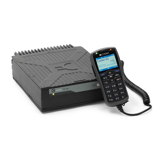
Page 27: The 2220 Handset
™ T NVOY RANSCEIVER The 2220 Handset The 2220 Handset is a control point for the Envoy™ Transceiver. The user interface provides an icon-based menu structure for easy setup and operation of the transceiver. Figure 2: 2220 Handset Power key... -
Page 28: The 2221 Handset
RANSCEIVER The 2221 Handset The 2221 Handset is a control point for the Envoy™ Transceiver. The user interface provides an icon-based menu structure for easy operation of the transceiver. It has a condensed set of keys for use in simpler communication scenarios. -
Page 29: The 2230 Desk Console
RANSCEIVER The 2230 Desk Console The 2230 Desk Console is a control point for the Envoy™ Transceiver. The user interface provides an icon-based menu structure for easy setup and operation of the transceiver. The desk console is standard for a fixed station. -
Page 30: The 2210 Rfu
NTRODUCTION ™ T NVOY RANSCEIVER The 2210 RFU The RFU modulates audio signals onto radio frequencies that can be transmitted on air, and demodulates the radio frequencies it receives into audio signals. It also interprets the instructions that you enter through the control point. Figure 5: 2210 RFU ™... -
Page 31: Using The Wizard
Using the wizard This section contains the following topics: • Overview of the wizard on page 10 • Using the wizard on page 12 ™ T NVOY RANSCEIVER EFERENCE ANUAL... -
Page 32: Overview Of The Wizard
SING THE WIZARD VERVIEW OF THE WIZARD Overview of the wizard The wizard is available if the transceiver: • has not been programmed with a profile • has a basic profile that has a common self address for each of the default HF networks: Selcall and CALM •... - Page 33 SING THE WIZARD VERVIEW OF THE WIZARD Related links: The Envoy™ Transceiver on page 4 Navigating the menu structure on page 89 ™ T NVOY RANSCEIVER EFERENCE ANUAL...
-
Page 34: Using The Wizard
SING THE WIZARD SING THE WIZARD Using the wizard The wizard should start automatically when a new transceiver is powered up for the first time. Figure 7: Wizard Startup screen NOTE: If the wizard screen doesn’t launch automatically, follow the instructions below. -
Page 35: Selecting A Language
SING THE WIZARD SING THE WIZARD Selecting a language NOTE: This step in the wizard is shown if you have multiple languages available. To select a language: Press to scroll to the language that you want to use on the control point, then press OK. -
Page 36: Setting The Location Of The Desk Console
SING THE WIZARD SING THE WIZARD Press to select the format that you want to use. If you want to review the information that you have entered, press move through the entries. Press (Save) to save the information. If you have not changed any of the time and date information, press (Close). - Page 37 SING THE WIZARD SING THE WIZARD Adding a channel NOTE: This step in the wizard is shown if you are permitted to add channels. To add a channel: Press (Yes) to add a channel, if required. Enter the name that you want to use for the channel. Press to move to the Tx entry.
- Page 38 SING THE WIZARD SING THE WIZARD Do one of the following: • If you want to add a scan table, press (Yes). • If you do not want to add a scan table, press (No), then continue from Entering a self address on page Do one of the following: •...
- Page 39 SING THE WIZARD SING THE WIZARD NOTE: The wizard automatically allocates this self address to the default HF networks: Selcall and CALM (if FED-STD-1045 ALE or MIL-STD-188-141B ALE option is installed). Do one of the following: • If you want to add a contact, press (Yes), then continue from Adding a contact on page...
- Page 40 SING THE WIZARD SING THE WIZARD Adding a simple call A simple call is a call that requires an address only at this stage of the definition process. To continue with adding a Selective, Channel Test, Emergency, Get Position or Send Position call: to move to the Selcall|ALE Address entry.
- Page 41 SING THE WIZARD SING THE WIZARD If you want to enter a message: • Start typing the message. NOTE: Press OK to start a new line, if required. • Press (Options), scroll to Save, then press (Select) to add the message to the call.
-
Page 42: Selecting An Antenna
SING THE WIZARD SING THE WIZARD Completing the contact To finish entering the information required for the contact: Press to move to the Call Description entry. The call type is entered automatically as the call description. Enter a new description for this call, if required. Press (Save) to save the information. -
Page 43: Selecting A Peripheral Device
When you select the peripheral device from the list, the transceiver automatically sets these properties. NOTE: Codan peripheral devices are listed by their type number, for example, 3031 Crosspatch. The type number for a Codan device is located on the front or serial number escutcheon. To select a peripheral device: Press to scroll to the type of peripheral device that is attached to the connector, then press OK. - Page 44 SING THE WIZARD SING THE WIZARD This page has been left blank intentionally. ™ T NVOY RANSCEIVER EFERENCE ANUAL...
- Page 45 Operating the transceiver This section contains the following topics: • Switching the transceiver on and off on page 24 • The channel screen on page 25 • Scanning channels on page 33 • Muting the transceiver on page 35 • Using the microphone on page 37 •...
-
Page 46: Operating The Transceiver
PERATING THE TRANSCEIVER WITCHING THE TRANSCEIVER ON AND OFF Switching the transceiver on and off Switching on the transceiver To switch on the transceiver: Press . The template screen, then the welcome screen (if set) are shown briefly, followed by the channel screen. Switching off the transceiver To switch off the transceiver: Do one of the following:... -
Page 47: The Channel Screen
PERATING THE TRANSCEIVER HE CHANNEL SCREEN The channel screen The channel screen shows the following information: • the name of the currently selected channel • the transmit and receive frequencies, if applicable • the status areas that show specific information about the transceiver •... -
Page 48: Figure 9: Scanning Screen
PERATING THE TRANSCEIVER HE CHANNEL SCREEN The status area of the screen provides six separate areas in which you can show information that is relevant for your operations. Your system administrator can choose the information that is shown in each status area. If encryptor/scrambler options are enabled, this information is shown in the top line of the status area. -
Page 49: Selecting A Channel
PERATING THE TRANSCEIVER HE CHANNEL SCREEN Selecting a channel To select a channel: Press PTT to exit to the channel or scanning screen. If the transceiver is scanning, press SCAN to switch off scanning. Press to scroll to the channel that you want to use. The channel is selected. -
Page 50: Selecting Information To Be Shown In A Status Area
Table 1: Information that may be shown in the status areas on the screen Item Description Empty Status area is blank Transceiver type Read from the template in the transceiver, for example, Envoy X1 or Envoy X2 User-defined text 1/2 Any text that you want to show on the screen ™ T NVOY... - Page 51 PERATING THE TRANSCEIVER HE CHANNEL SCREEN Table 1: Information that may be shown in the status areas on the screen (cont.) Item Description Altitude, Derived from GPS signals from a GPS receiver Latitude/Northing, Longitude/Easting, Speed PA temperature Temperature of the heatsink Tx power Monitored transmit power from the transceiver Rx level...
- Page 52 PERATING THE TRANSCEIVER HE CHANNEL SCREEN Table 1: Information that may be shown in the status areas on the screen (cont.) Item Description 2.4 kbit/s Data Modem throughput Grey LED, solid: modem is not in a link Green LED, solid: modem is enabled and a computer is communicating with it via VCOM Green LED, flashing: modem is in a link and received the link Red LED, flashing: modem is in a link and started the link...
-
Page 53: Selecting A Theme
PERATING THE TRANSCEIVER HE CHANNEL SCREEN Selecting a theme You can select one of the following themes for the display in the control point. You can select one theme for use during the day, and another for use during the night. Figure 11: Available themes for the display in the control point Theme... - Page 54 PERATING THE TRANSCEIVER HE CHANNEL SCREEN If you have set a night theme, do the following: to scroll to the Night Display Start entry. • Press • Press to select the time that you want to start displaying the night time theme.
-
Page 55: Scanning Channels
PERATING THE TRANSCEIVER CANNING CHANNELS Scanning channels If you intend to receive calls on several channels, switch on scanning. When scanning is switched on, the transceiver sequentially selects each channel/mode in your scan tables to detect incoming calls. The channels are scanned in a continuous cycle. By default, mute is switched on automatically when scanning is switched on. -
Page 56: Switching Scanning On Or Off
PERATING THE TRANSCEIVER CANNING CHANNELS Switching scanning on or off To switch scanning on or off: Press SCAN. If a call is not in progress, scanning is toggled on or off. If a call is in progress, the call is ended and the transceiver begins scanning. If a call from a modem (or any other peripheral device) is in progress, you are prompted to break the system lock to resume scanning. -
Page 57: Muting The Transceiver
PERATING THE TRANSCEIVER UTING THE TRANSCEIVER Muting the transceiver When the transceiver is set to a channel or is scanning channels, and mute is switched off, you hear on-air signals on each channel. If you do not want to listen to this, you can silence the transceiver by switching on mute. -
Page 58: Selecting The Mute Type
PERATING THE TRANSCEIVER UTING THE TRANSCEIVER Selecting the mute type To select the mute type: If you are using a 2220 Handset or 2230 Desk Console, press to toggle the mute type between Selcall mute (S) and Voice mute (V). If you are using a 2221 Handset: •... -
Page 59: Using The Microphone
CAUTION: Your conversation can be monitored by anyone tuned to your transmit frequency, unless you are using one of Codan’s encryption options. Your signal can potentially travel very large distances. If PTT is held continuously for a certain length of time, the system stops transmission, switches to receive and shows an error message on the control point. -
Page 60: Manually Tuning The Antenna
PERATING THE TRANSCEIVER ANUALLY TUNING THE ANTENNA Manually tuning the antenna WARNING: Before using the antenna system see the safety information provided. NOTE: If the transceiver is connected to an automatic tuning antenna, it tunes the antenna automatically when required. You may need to manually tune the antenna if you are receiving on a new channel, or if you want to check the SWR value for the antenna. -
Page 61: Selecting A Language
PERATING THE TRANSCEIVER ELECTING A LANGUAGE Selecting a language The default language for the control point is English, however, you may have other language options available for the control point. Figure 12: Select Language screen To select a language: (Select Language). From the main menu, select Press to scroll to the language that you want to use on the control point,... -
Page 62: Setting The Time And Date
PERATING THE TRANSCEIVER ETTING THE TIME AND DATE Setting the time and date The transceiver is set to UTC time in the factory. You set the local time and time zone for the location of the control point. This feature is useful if you have a communication network that spreads over several time zones, or you need to time stamp your transmissions according to the current time at longitude zero. -
Page 63: Setting The Brightness Of The Display
PERATING THE TRANSCEIVER ETTING THE BRIGHTNESS OF THE DISPLAY Setting the brightness of the display To set the brightness: Do one of the following: • Press + 0. • From the main menu, select (General), then (Brightness). Press to scroll to the value that you want to set, then press OK. Press (Save) to save the information. -
Page 64: Setting The Display Timeout
PERATING THE TRANSCEIVER ETTING THE DISPLAY TIMEOUT Setting the display timeout You can set the length of time that the display and keypad backlight remains on after the last activity on the control point. After this time, the backlight value drops to Low. When a key is pressed, the backlighting returns to the value set in the Brightness entry. -
Page 65: Setting The Location Of The Desk Console
PERATING THE TRANSCEIVER ETTING THE LOCATION OF THE DESK CONSOLE Setting the location of the desk console The desk console may be connected directly to the transceiver, or it may be connected remotely. Figure 13: Connection between RFU and desk console using 10-way to 8-way cable r o l o n t... -
Page 66: Figure 14: Connection Between Rfu And Desk Console Using Ethernet Cables And Optional Switch
PERATING THE TRANSCEIVER ETTING THE LOCATION OF THE DESK CONSOLE Figure 14: Connection between RFU and desk console using Ethernet cables and optional switch r o l o n t e n n a n t e n n a n t t e r b a t 1 5 -... -
Page 67: Calling
PERATING THE TRANSCEIVER ALLING Calling This section describes how to make the various types of calls from the transceiver. You can make a call to a contact, return or repeat a call from the Call History, or enter information at the time of the call. Related links: Making a call to a contact on page 45 Making a call from the Call History on page 46... -
Page 68: Adding A Contact
Adding a contact on page 163 Making a call from the Call History The Envoy™ Transceiver stores information on the calls that you send and receive. The detailed call history is accessed by holding CALL, then pressing to scroll to the Call History tab. -
Page 69: Making A Call From The Emergency Key
PERATING THE TRANSCEIVER ALLING Related links: Call Key Options on page 207 Making a Selective call on page 48 Making a Channel Test call on page 50 Making a Message call on page 53 Making a Phone call on page 56 Making a Send Position call on page 57 Making a Get Position call on page 58 Making a Get Status call on page 60... -
Page 70: General Calling
PERATING THE TRANSCEIVER ALLING General calling Figure 15: Call screen with Call Log navigation call type HF network indicator address incoming call outgoing call select HF network Related links: Making a Selective call on page 48 Making a Channel Test call on page 50 Making a Message call on page 53 Making a Phone call on page 56 Making a Send Position call on page 57... - Page 71 Selective call on page 440 Entering text in a field on page 103 Using multiple addresses for calls in an ALE/CALM HF network on page 453 Group calls in a Codan Selcall HF network on page 452 ™ T NVOY...
- Page 72 ALLING Making a Channel Test call A Channel Test call enables you to test the quality of a channel/mode in a Codan Selcall HF network, and is sometimes referred to as a Beacon call. If you have the MIL-STD-188-141B ALE option installed, a Channel Test call may be made in an ALE/CALM HF network to replace information in the LQA database, and to perform a manual sounding operation.
- Page 73 PERATING THE TRANSCEIVER ALLING Do one of the following: To repeat the call to the last address used, press CALL. • To call a different station, enter the address, then press CALL. • • To repeat or return a call from the Call Log, press to scroll to the call, press to select your required call type, then press CALL.
- Page 74 PERATING THE TRANSCEIVER ALLING Related links: Channel Test call on page 435 Entering text in a field on page 103 Selecting information to be shown in a status area on page 28 Making a Channel Test call in an ALE/CALM HF network NOTE: A Channel Test call in an ALE/CALM HF network is available if the MIL-STD-188-141B ALE option is installed.
- Page 75 PERATING THE TRANSCEIVER ALLING The LQA score for each channel is shown. NOTE: If you switch to advanced view, BER/SINAD information is displayed in the LQA screen. Do one of the following: • Press CALL to start a call to this station using the best channel. •...
- Page 76 PERATING THE TRANSCEIVER ALLING If you do not want to use the HF network shown at the top right of the screen: • Press (Options). • Scroll to HF Networks, then press (Select). • Scroll to the HF network that you want to use, then press OK. Press to select the Message call type if it is not selected.
- Page 77 Message call on page 438 Entering text in a field on page 103 Using multiple addresses for calls in an ALE/CALM HF network on page 453 Group calls in a Codan Selcall HF network on page 452 ™ T NVOY...
- Page 78 PERATING THE TRANSCEIVER ALLING Making a Phone call If you want to speak with an operator on a phone line, make a Phone call to that number. The transceiver makes an HF call to a telephone station (phone link), which connects through to the public telephone network.
- Page 79 Entering text in a field on page 103 Using multiple addresses for calls in an ALE/CALM HF network on page 453 Group calls in a Codan Selcall HF network on page 452 Making a Send Position call If you want to send your GPS information to another station, make a Send Position call.
- Page 80 My Position on page 252 Using multiple addresses for calls in an ALE/CALM HF network on page 453 Group calls in a Codan Selcall HF network on page 452 GPS Show Options on page 250 Making a Get Position call If you want to obtain the GPS position of a specific station that has valid GPS information, make a Get Position call to that station.
- Page 81 PERATING THE TRANSCEIVER ALLING If you do not want to use the HF network shown at the top right of the screen: • Press (Options). • Scroll to HF Networks, then press (Select). • Scroll to the HF network that you want to use, then press OK. Press to select the Get Position call type if it is not selected.
- Page 82 PERATING THE TRANSCEIVER ALLING Making a Get Status call If you want to obtain information on the status of a transceiver at a specific station, such as the power output of the transmitter or the firmware versions installed, make a Get Status call to that station.
-
Page 83: Figure 16: Available Status Types For A Get Status Call In A Selcall
If you selected ?: Other as the status type, enter the text/command that you want to send (Options), scroll to OK (Select). NOTE: For information on over-the-air commands, please contact your Codan representative. If prompted, press to scroll to the channel that you want to use, then press CALL. - Page 84 PERATING THE TRANSCEIVER ALLING Making an Emergency call If you want to trigger an emergency alert tone at a particular station and speak with an operator, make an Emergency call. If the GPS Call option is installed in the transceiver (and you have connected and configured a GPS receiver, or GPS information stored in Settings >...
- Page 85 Entering text in a field on page 103 Using multiple addresses for calls in an ALE/CALM HF network on page 453 Group calls in a Codan Selcall HF network on page 452 My Position on page 252 Making a call from the Emergency key on page 47...
- Page 86 PERATING THE TRANSCEIVER ALLING NOTE: The RFDS Emergency call type is only available if an RFDS HF network is selected. If you do not want to use the HF network shown at the top right of the screen: • Press (Options).
- Page 87 PERATING THE TRANSCEIVER ALLING NOTE: The Marine Emergency call type is only available if a Marine Tone HF network is selected. If you do not want to use the HF network shown at the top right of the screen: • Press (Options).
- Page 88 PERATING THE TRANSCEIVER ALLING If you do not want to use the HF network shown at the top right of the screen: • Press (Options). Scroll to HF Networks, then press • (Select). • Scroll to the HF network that you want to use, then press OK. Press to select the ALE Sounding call type if it is not selected.
-
Page 89: Using The Clarifier
PERATING THE TRANSCEIVER SING THE CLARIFIER Using the clarifier The clarifier is a feature that enables you to adjust the receive frequency to compensate for any frequency offset between your transceiver and the remote transceiver, thus improving the quality of received voice. To use the clarifier: Go to the channel screen and ensure that scanning is switched off. -
Page 90: Reducing Background Noise With Easitalk
PERATING THE TRANSCEIVER ™ EDUCING BACKGROUND NOISE WITH ASITALK Reducing background noise with Easitalk™ The Easitalk™ feature enables you to reduce the level of background noise that is present when you listen to a channel. NOTE: Easitalk™ uses one of three DSP algorithms to reduce the background noise. -
Page 91: Viewing Information About Your Transceiver
PERATING THE TRANSCEIVER IEWING INFORMATION ABOUT YOUR TRANSCEIVER Viewing information about your transceiver Overview of information in the transceiver The transceiver contains information on: • hardware options that have been fitted • sales options that have been enabled • the electronic serial number of the RFU •... - Page 92 PERATING THE TRANSCEIVER IEWING INFORMATION ABOUT YOUR TRANSCEIVER Viewing the ESN To view the ESN: From the main menu, select (Information), then (Option Password). The ESN is shown on the Option Password screen. NOTE: If you want to view the ESN of the RFU and the CP, view the Version screen in advanced view.
- Page 93 Selecting information to be shown in a status area on page 28 Viewing IP information The USB interface on the control point supports the RNDIS protocol, which provides a virtual IP connection over USB. The Envoy™ Transceiver connects to TPS via this connection. To view the IP information:...
- Page 94 PERATING THE TRANSCEIVER IEWING INFORMATION ABOUT YOUR TRANSCEIVER Viewing licence information To view licence information: From the main menu, select (Information), then (Licence). Licence information is provided for the following components of the firmware: • alsa-lib • alsa-utils • base_libs •...
-
Page 95: Using Gps
PERATING THE TRANSCEIVER SING Using GPS Overview of GPS Access to GPS information and sending and receiving GPS information is available if you have the GPS Call option enabled in your transceiver. GPS information may be sourced from a GPS receiver, selected as a peripheral device, or from information set up in Settings >... -
Page 96: Distance And Bearing
SING Distance and bearing The Envoy™ Transceiver calculates distance and bearing information between your GPS information (last fix from GPS receiver or information entered into Settings > GPS > My Position), and a waypoint that you select from a Get/Send Position call in the Call History or Contacts. -
Page 97: Viewing Gps Information
PERATING THE TRANSCEIVER SING Viewing GPS information NOTE: You can view GPS information if the GPS Call option is installed. GPS information may be provided via a connected GPS receiver or data entered into Settings > GPS > My Position. To view GPS information: From the main menu, select (General), then... - Page 98 PERATING THE TRANSCEIVER SING Table 2: GPS information (cont.) Description Map of visible satellites. The satellites that are coloured blue provide the strongest signals and this information is used to establish the position of the receiver. The other satellites are visible, but the signal is weaker and information is ignored.
-
Page 99: Using Encryption
PERATING THE TRANSCEIVER SING ENCRYPTION Using encryption Related links: Encryption on page 317 Switching the secure feature on or off on page 77 Selecting an encryptor on page 324 Adding a secure key on page 325 Selecting a secure key on page 80 Editing a secure key on page 327 Deleting a secure key on page 328 Switching the secure feature on or off... - Page 100 PERATING THE TRANSCEIVER SING ENCRYPTION For CIVS voice scrambling you will see: Secure Clear privacy code For CES-128 voice encryption you will see: Secure Clear secure index for CES-128 secure key For AES-256 digital voice encryption you will see: Secure Clear digital secure index...
- Page 101 PERATING THE TRANSCEIVER SING ENCRYPTION For AES-256 data encryption you will see: Secure Clear digital secure index for key prefix AES-256 digital data secure key If you have more than one encryptor/scrambler available, you can change to another encryptor/scrambler, if permitted. If you are using CES-128 voice encryption with a 2220 Handset or 2230 Desk Console, press to go to secure standby mode, if enabled and required.
-
Page 102: Selecting A Secure Key
PERATING THE TRANSCEIVER SING ENCRYPTION Selecting a secure key If an encryptor contains two or more keys, you have the option of selecting a different key for encryption, if permitted. When AES-256 digital voice and data encryptors are used together, the selected key is common to both. To select a secure key: If you are using a 2220 Handset or 2230 Desk Console, do one of the following: •... -
Page 103: Changing The Privacy Code
PERATING THE TRANSCEIVER SING ENCRYPTION Changing the privacy code The CIVS scrambler operates on one of 32 codes. You can change the current privacy code, if permitted. To select a privacy code: If you are using a 2220 Handset or 2230 Desk Console, do one of the following: •... -
Page 104: Using A Crosspatch
PERATING THE TRANSCEIVER SING A CROSSPATCH Using a crosspatch Overview of the 3031 Crosspatch The 3031 Crosspatch is a device that connects an HF communication system with a VHF or UHF communication system. NOTE: For details on installing the crosspatch and its operation, please see the documentation provided with the device. -
Page 105: Changing The Operating Mode Of The Crosspatch
PERATING THE TRANSCEIVER SING A CROSSPATCH Related links: Selecting a peripheral device on page 195 Selecting information to be shown in a status area on page 28 Changing the operating mode of the crosspatch To change the operating mode of the crosspatch: If you are using a 2220 Handset or 2230 Desk Console, press 5. -
Page 106: Upgrading The Transceiver Via A Usb Stick
To manage profiles, firmware, and secure keys: Connect your USB stick to the control point using a standard USB A (female) to micro USB cable (Codan part number 67-90406). The USB stick is detected automatically. A Select Task icon ( ) is now available in the main menu screen. -
Page 107: Entering A Password For An Option
26-digit option code that must be entered to enable the option in the transceiver’s firmware. If you forget your admin PIN, contact Codan, quote the ESN of your transceiver, and you will be given an option code for deleting the PIN. -
Page 108: Performing A Self-Test
PERATING THE TRANSCEIVER ERFORMING A SELF TEST Performing a self-test The Envoy™ Transceiver has a series of built-in tests that may be completed to assess a particular aspect of functionality. To perform a self-test: From the main menu, select (General), then (Self Tests). -
Page 109: Finding An Rfu
PERATING THE TRANSCEIVER INDING AN Finding an RFU If your organisation has several RFUs and control points connected to a LAN via an Ethernet switch, you have to allocate a different IP address to each unit in Settings > Connectivity. When you enter the Find RFU screen, the transceiver searches for IP addresses on the LAN and provides a list from which you can select. - Page 110 PERATING THE TRANSCEIVER INDING AN This page has been left blank intentionally. ™ T NVOY RANSCEIVER EFERENCE ANUAL...
- Page 111 Navigating the menu structure This section contains the following topics: • Menu structure on page 90 • Navigating the menu structure on page 92 • Overview of basic and advanced views on page 94 • Overview of user and admin levels on page 96 •...
-
Page 112: Menu Structure
AVIGATING THE MENU STRUCTURE ENU STRUCTURE Menu structure The menu structure comprises a main menu and a series of submenus that are accessed via the main menu. Each menu and submenu is represented by an icon. Some icons provide direct access to an input/view screen, while other icons provide a list of entries for the menu. -
Page 113: Figure 21: Menu Structure (Admin Level)
AVIGATING THE MENU STRUCTURE ENU STRUCTURE Figure 21: Menu structure (admin level) Setup Wizard Add Channel User Data Channels Scan Tables HF Networks Phone Links Contacts NETs Messages Macros Modes Peripherals Settings Control Point Configuration Connectors Scan Calling Audio Security Connectivity Admin Login/Logout Advanced View... -
Page 114: Navigating The Menu Structure
AVIGATING THE MENU STRUCTURE AVIGATING THE MENU STRUCTURE Navigating the menu structure The menu structure comprises a main menu and a series of submenus that are accessed via the main menu. Navigation keys enable you to highlight an icon, then press OK to select that menu. - Page 115 AVIGATING THE MENU STRUCTURE AVIGATING THE MENU STRUCTURE Related links: Menu structure on page 90 Selecting an icon on page 101 Selecting a value from a list on page 107 Finding a word or value on page 99 Selecting/deselecting a check box on page 108 ™...
-
Page 116: Overview Of Basic And Advanced Views
AVIGATING THE MENU STRUCTURE VERVIEW OF BASIC AND ADVANCED VIEWS Overview of basic and advanced views There are two views of information in the user interface of the control point: basic and advanced. The contents of basic and advanced views are pre-determined and cannot be changed. -
Page 117: Switching Between Basic And Advanced Views
AVIGATING THE MENU STRUCTURE VERVIEW OF BASIC AND ADVANCED VIEWS Switching between basic and advanced views The user can switch between basic and advanced views to either: • simplify the user interface of the control point (basic view), or • access advanced settings that they are permitted to change (advanced view) To switch between views: Press... -
Page 118: Overview Of User And Admin Levels
AVIGATING THE MENU STRUCTURE VERVIEW OF USER AND ADMIN LEVELS Overview of user and admin levels There are two levels of access to information in the user interface of the control point: user and admin. You can change which entries the user can see and edit by applying access rights to the profile in TPS. -
Page 119: Logging In To Admin Level
AVIGATING THE MENU STRUCTURE VERVIEW OF USER AND ADMIN LEVELS Figure 27: Locked, hidden and advanced indicators entry locked at locked or hidden available in a higher level at admin level advanced view NOTE: Setting the access rights on an entry, that is, whether it is admin locked and/or admin hidden, can only be performed via TPS when logged in to admin level. -
Page 120: Logging Out Of Admin Level
AVIGATING THE MENU STRUCTURE VERVIEW OF USER AND ADMIN LEVELS Enter the PIN provided by your system administrator, then press OK. Logging out of admin level Admin level is used for modifying settings that are not available at user level. To log out of admin level: Press until the main menu screen is shown. -
Page 121: Finding A Word Or Value
AVIGATING THE MENU STRUCTURE INDING A WORD OR VALUE Finding a word or value The quickest way to find an entry or a value in the user interface of the control point is to use the Find function, which is available via the key when the highlighted icon contains submenus or lists of entries. - Page 122 AVIGATING THE MENU STRUCTURE INDING A WORD OR VALUE Enter more characters to refine your search. The icon that is shown with each item in the list indicates the location of the information. For example, if appears next to the item, then it is located in Channels.
-
Page 123: Selecting An Icon
AVIGATING THE MENU STRUCTURE ELECTING AN ICON Selecting an icon The top levels of the menu structure are represented by icons. In order to enter the menu represented by the icon, you need to select the icon. Figure 29: Highlighted icon highlighted icon To select an icon: Use , ,... -
Page 124: Selecting A Function From The Menu Bar
AVIGATING THE MENU STRUCTURE ELECTING A FUNCTION FROM THE MENU BAR Selecting a function from the menu bar The menu bar at the bottom of the screen provides varying functions, depending on the context. You can select a function directly, or activate a pop-up from the menu bar by pressing the corresponding key ( ). -
Page 125: Entering Text In A Field
AVIGATING THE MENU STRUCTURE NTERING TEXT IN A FIELD Entering text in a field You may need to enter text into a field within an entry. This may be a name given to some user data, or it may be a specific value, such as a frequency. When you first enter an editable text field, either by selecting a menu or using the navigation keys, any existing text that you can edit is highlighted. -
Page 126: Figure 32: Character-Entry Mode Indicator
AVIGATING THE MENU STRUCTURE NTERING TEXT IN A FIELD Figure 32: Character-entry mode indicator character-entry mode indicator Table 3: Character-entry mode Character-entry mode Indicator (English) All upper-case letters All lower-case letters Leading-capital letters Numbers Do any of the following: • Press to move the cursor to the point at which you want to enter text. -
Page 127: Entering A Special Character (2220/2230)
AVIGATING THE MENU STRUCTURE NTERING TEXT IN A FIELD Entering a special character (2220/2230) You can enter special characters in messages, names, contacts, and in addresses of stations that you call. NOTE: If the FED-STD-1045 ALE/CALM option or MIL-STD-188-141B ALE option is installed in your transceiver, the key may be used to enter the global ALL address syntax (@?@) or special ALE addressing characters easily. -
Page 128: Entering Text With The 2221 Handset
AVIGATING THE MENU STRUCTURE 2221 H NTERING TEXT WITH THE ANDSET Entering text with the 2221 Handset The 2221 Handset does not have alphanumeric keys, however, you can still enter text into fields within the user interface. CAUTION: This process describes how to enter text into an entry field using the virtual keypad, then save the text back to the entry. -
Page 129: Selecting A Value From A List
AVIGATING THE MENU STRUCTURE ELECTING A VALUE FROM A LIST Selecting a value from a list When you select an entry that has a list of values, either by selecting an icon or using navigation keys, the field is highlighted to show that it can be edited, indicators appear on one or both sides of the field to show that multiple values are available. -
Page 130: Selecting/Deselecting A Check Box
AVIGATING THE MENU STRUCTURE ELECTING DESELECTING A CHECK BOX Selecting/deselecting a check box There are some entries in the menu structure that require you to enable or disable a particular feature via a check box. When the check box contains a tick ( ), the feature is enabled. -
Page 131: Moving A Slider
AVIGATING THE MENU STRUCTURE OVING A SLIDER Moving a slider Some values in the user interface of the control point are represented by a slider. Figure 35: A slider value slider navigation key indicator To move a slider: Press any of the navigation keys suggested in the navigation key indicator to adjust the slider. -
Page 132: Changing The Order Of Items In A List
AVIGATING THE MENU STRUCTURE HANGING THE ORDER OF ITEMS IN A LIST Changing the order of items in a list In some areas of the user interface of the control point, you are able to change the order in which items appear in a list, which impacts how the item is viewed, or when each item may be used. -
Page 133: Saving Your Changes
AVIGATING THE MENU STRUCTURE AVING YOUR CHANGES Saving your changes When information in an entry has been changed, either by editing existing text or selecting a different value from a list, an asterisk is added to the title of the screen. Figure 36: Screen that has changes to be saved asterisk indicates... - Page 134 AVIGATING THE MENU STRUCTURE AVING YOUR CHANGES This page has been left blank intentionally. ™ T NVOY RANSCEIVER EFERENCE ANUAL...
-
Page 135: Structure Of Information
Structure of information This section contains the following topics: • Structure of user information on page 114 • Structure of contact and call information on page 115 ™ T NVOY RANSCEIVER EFERENCE ANUAL... -
Page 136: Structure Of User Information
TRUCTURE OF USER INFORMATION Structure of user information Information in the Envoy™ Transceiver is stored like blocks in a building. Basic blocks are populated with information first, then these blocks, along with different blocks, are assembled into larger blocks. Ultimately, one of the top-level blocks is used to make a call. -
Page 137: Structure Of Contact And Call Information
The basic structure of call information in a contact is shown in Figure Figure 38: Structure of call information for a contact in the Envoy™ Transceiver Emergency Available HF networks HF network... - Page 138 TRUCTURE OF INFORMATION TRUCTURE OF CONTACT AND CALL INFORMATION This page has been left blank intentionally. ™ T NVOY RANSCEIVER EFERENCE ANUAL...
-
Page 139: Channels
Channels This section contains the following topics: • Overview of channels on page 118 • Entries for a channel on page 119 • Working with channels on page 123 ™ T NVOY RANSCEIVER EFERENCE ANUAL... -
Page 140: Overview Of Channels
HANNELS VERVIEW OF CHANNELS Overview of channels A channel is a pair of frequencies that is programmed in the transceiver and used to transmit and receive signals on air. A channel has a name, a receive frequency, an optional transmit frequency, a mode, the preferred mode, a power level, and an antenna. -
Page 141: Entries For A Channel
Ch 1 A1 and Ch 1 A2. CAUTION: You should be aware of any restrictions placed on channel names in your transceiver when it is used with a Codan HF data modem, radio/telephone interconnect, or InterNav© software. See the documentation provided with this equipment. -
Page 142: Modes
HANNELS NTRIES FOR A CHANNEL Modes Modes are available in the transceiver when a particular filter is enabled. When the standard IF filter is enabled, the available modes are USB and LSB. If a different filter is enabled, other modes are available. For example, if you have a wide IF filter enabled, USBW and LSBW are available. -
Page 143: Antenna
HANNELS NTRIES FOR A CHANNEL Antenna The Antenna entry sets the antenna that is used with this channel when a Dual Antenna Adaptor is attached to the transceiver at the base station. The Dual Antenna Adaptor may be used with two broadband antennas, or a broadband antenna and a 9103 tuner with a tuned whip antenna, in either position. - Page 144 HANNELS NTRIES FOR A CHANNEL If you want the transceiver to use: • antenna 1 when the channel is selected, select 1 • antenna 2 when the channel is selected, select 2 When the transceiver starts scanning, it selects the antenna that it uses according to the following: •...
-
Page 145: Working With Channels
HANNELS ORKING WITH CHANNELS Working with channels Related links: Entries for a channel on page 119 Overview of scan tables on page 128 Available modes on page 282 Tx Power on page 221 Navigating the menu structure on page 92 Entering text in a field on page 103 Selecting a value from a list on page 107 Saving your changes on page 111... - Page 146 HANNELS ORKING WITH CHANNELS Do one of the following: • If there are no channels programmed in the transceiver, press (Add). • If there are some existing channels programmed in the transceiver, scroll to the channel after which you want to add the new channel, press (Options), scroll to Add, then press (Select) to add a channel.
-
Page 147: Editing A Channel
HANNELS ORKING WITH CHANNELS Press to select the value that you want to use from the following: To transmit at the power level set in the Tx Power entry, select Leave • as is. • To transmit signals at the value set for the low power range, select Low. •... -
Page 148: Moving A Channel
HANNELS ORKING WITH CHANNELS Moving a channel Channels appear in the list in the order in which they are created. You can move a channel to a different rank in the list to suit your needs, for example, you may want to place a channel that you use frequently at the top of the list. - Page 149 Scan tables This section contains the following topics: • Overview of scan tables on page 128 • Entries for a scan table on page 130 • Working with scan tables on page 133 ™ T NVOY RANSCEIVER EFERENCE ANUAL...
-
Page 150: Scan Tables
CAN TABLES VERVIEW OF SCAN TABLES Overview of scan tables A scan table is a notional grouping of channels stored in a transceiver. The number of scan tables that you can add in your transceiver varies depending on the transceiver type and options installed, however, only 100 channels may be scanned at any one time. -
Page 151: Figure 41: Information For A Scan Table
CAN TABLES VERVIEW OF SCAN TABLES Figure 41: Information for a scan table Scan Tables Table 1 Scan: Selected Scan Channels: Ch 01/USB Ch 03/USB Voice Detect: Not selected Channel Dwell Time: Auto HF Networks*: Selcall, CALM Data: Selected Table 2 Scan: Selected Scan Channels:... -
Page 152: Entries For A Scan Table
CAN TABLES NTRIES FOR A SCAN TABLE Entries for a scan table Scan table name A scan table has a name that uniquely identifies it, and makes it available for selection in other areas of the user interface of the control point. Scanning a scan table You can include a group of channels in a scan table, and set up some common properties for how these channels are scanned. -
Page 153: Hf Network
NTRIES FOR A SCAN TABLE Table 4: Default channel dwell time for each type of HF network or detection requirement HF network type Detection requirement Default channel dwell time (msec) Codan Selcall None selected Voice Data Open Selcall None selected Voice... -
Page 154: Data
CAN TABLES NTRIES FOR A SCAN TABLE Data NOTE: The Data entry should be set when using the 2.4 kbit/s Data Modem or any external modem in a scanning Selcall system. It is not required when using ALE/CALM systems. The Data entry sets whether or not scanning is slowed to a value suitable for a 3012-type modem to detect the calling signal from another 3012-type modem, stop scanning, and initiate the link. -
Page 155: Working With Scan Tables
CAN TABLES ORKING WITH SCAN TABLES Working with scan tables Related links: Entries for a scan table on page 130 Overview of HF networks on page 140 Scan channels on page 130 Navigating the menu structure on page 92 Entering text in a field on page 103 Selecting a value from a list on page 107 Selecting/deselecting a check box on page 108 Saving your changes on page 111... - Page 156 CAN TABLES ORKING WITH SCAN TABLES If you want the channels in the scan table to be scanned for voice signals regardless of the types of HF networks to which this scan table is allocated, press OK to select the On check box. Press to move to the Channel Dwell Time entry.
- Page 157 CAN TABLES ORKING WITH SCAN TABLES Press (Options), scroll to Save, then press (Select). Press (Save) to save the information. Related links: Duplicating a channel in a scan table on page 136 Deleting a channel from a scan table When you are adding or editing a scan table, you may want to delete channels that you have added to the scan table.
- Page 158 CAN TABLES ORKING WITH SCAN TABLES Duplicating a channel in a scan table If a channel has more than one allowed mode, you can select the mode that is scanned when you add the channel to the scan table. If you want to have all allowed modes for the channel scanned, duplicate the channel and select a different allowed mode.
-
Page 159: Editing A Scan Table
CAN TABLES ORKING WITH SCAN TABLES Press (Options), scroll to Save, then press (Select). Press (Save) to save the information. Editing a scan table Editing a scan table is similar to adding a scan table. To edit a scan table: From the main menu, select (User Data), then (Scan Tables). - Page 160 CAN TABLES ORKING WITH SCAN TABLES This page has been left blank intentionally. ™ T NVOY RANSCEIVER EFERENCE ANUAL...
- Page 161 HF networks This section contains the following topics: • Overview of HF networks on page 140 • Entries for an HF network on page 142 • Working with HF networks on page 147 ™ T NVOY RANSCEIVER EFERENCE ANUAL...
-
Page 162: Hf Networks
HF networks are based on call systems. A call system is a method of making and receiving calls. For example, if you are in an HF network that uses the Codan Selcall or Open Selcall call system, you make calls by entering the address of the station that you want to call, then selecting the channel/mode that you want to use. - Page 163 NETWORKS VERVIEW OF NETWORKS Related links: Entries for an HF network on page 142 Adding an HF network on page 147 ™ T NVOY RANSCEIVER EFERENCE ANUAL...
-
Page 164: Entries For An Hf Network
ALE/CALM. The call systems from which you can select depend on the options installed in the transceiver. If your HF network uses the Codan Selcall or Open Selcall call system, you can make calls by selecting an appropriate channel/mode then entering the address of the station that you want to call as part of the calling process. -
Page 165: Self Address
If you want to use the ALE/CALM call system to automate the selection of channels, you must install the FED-STD-1045 ALE/CALM option in the transceiver. CALM stands for Codan Automated Link Management. The FED-STD-1045 ALE/CALM option enables the transceiver to test the signal propagation qualities of your channels using soundings, and build a profile of each channel’s suitability for use at different times of the day and night. -
Page 166: Global
NETWORKS NTRIES FOR AN NETWORK Global An HF network typically has channel information associated with it in the form of scan tables. If you want the HF network and self address to be used to make and receive calls on any channel that is programmed in the transceiver, select the On check box for the Global entry. -
Page 167: Sounding Interval
Privacy mode The Privacy Mode entry applies to Codan Selcall and ALE/CALM HF networks only. The privacy mode is the method used to encrypt the data content of calls between stations. If you select Group, you must enter an appropriate password into the Privacy Password entry. -
Page 168: Privacy Password
HF networks. Privacy password The Privacy Password entry applies to Codan Selcall and ALE/CALM HF networks where the privacy mode is set to Group. The privacy password is defined arbitrarily by the system administrator or user, and programmed into the transceiver. -
Page 169: Working With Hf Networks
Selecting/deselecting a check box on page 108 Saving your changes on page 111 Group calls in a Codan Selcall HF network on page 452 Adding an HF network An HF network provides a relationship between the call system, self address and scan tables. - Page 170 Press Press to scroll through the following values: • To make calls between two stations using a Codan protocol with special formatting, select None. • To encrypt data in calls between two stations using an agreed privacy password, select Group.
-
Page 171: Editing An Hf Network
NETWORKS ORKING WITH NETWORKS If you want the HF network to be used for receiving calls only, press OK to select the On check box. If you want to review the information that you have entered, press move through the entries. Press (Save) to save the information. - Page 172 NETWORKS ORKING WITH NETWORKS This page has been left blank intentionally. ™ T NVOY RANSCEIVER EFERENCE ANUAL...
- Page 173 Phone links This section contains the following topics: • Overview of phone links on page 152 • Entries for a phone link on page 153 • Working with phone links on page 154 ™ T NVOY RANSCEIVER EFERENCE ANUAL...
-
Page 174: Phone Links
A phone link is a bundle of information that defines how your station communicates with a telephone station. A telephone station comprises a Codan HF transceiver that is connected to a radio/telephone interconnect unit. This unit routes Phone calls from HF transceivers to the public telephone network, and vice versa. -
Page 175: Entries For A Phone Link
HONE LINKS NTRIES FOR A PHONE LINK Entries for a phone link Phone link name The phone link has a name that uniquely identifies the telephone station to which you want to connect, and enables it to be easily selected in other areas of the user interface of the control point. -
Page 176: Working With Phone Links
HONE LINKS ORKING WITH PHONE LINKS Working with phone links Related links: Entries for a phone link on page 153 Navigating the menu structure on page 92 Entering text in a field on page 103 Selecting a value from a list on page 107 Saving your changes on page 111 Adding a phone link A phone link contains information about how you want to communicate with the... -
Page 177: Editing A Phone Link
HONE LINKS ORKING WITH PHONE LINKS If you want to review the information that you have entered, press move through the entries. Press (Save) to save the information. Editing a phone link Editing a phone link is similar to adding a phone link. To edit a phone link: From the main menu, select (User Data), then... - Page 178 HONE LINKS ORKING WITH PHONE LINKS This page has been left blank intentionally. ™ T NVOY RANSCEIVER EFERENCE ANUAL...
-
Page 179: Contacts
Contacts This section contains the following topics: • Overview of contacts on page 158 • Entries for a contact on page 160 • Working with contacts on page 163 ™ T NVOY RANSCEIVER EFERENCE ANUAL... -
Page 180: Overview Of Contacts
ONTACTS VERVIEW OF CONTACTS Overview of contacts A contact is an operator or organisation who you want to call. You can define a number of potential calls that you may want to make to this contact, depending on location and the type of interaction that is required. For example, you may want to call Bob. -
Page 181: Chain Call
ONTACTS VERVIEW OF CONTACTS Related links: Adding a contact on page 163 Chain call on page 159 Chain call A chain call starts automatically when you hold the key for 2 sec. A chain call makes the calls for the selected emergency contact in succession. The length of time between calls is set in Settings >... -
Page 182: Entries For A Contact
ONTACTS NTRIES FOR A CONTACT Entries for a contact Contact name A contact is a person or organisation for whom you want to store pre-defined call information. One contact may have several different methods of being called. The name of the contact is the label, in any supported language, identifying this bundle of call information. -
Page 183: Ale|Selcall Address
ONTACTS NTRIES FOR A CONTACT ALE|Selcall address The address is used to identify the station that you want to call. This address is sent with the preamble when the call is made. A station that is scanning to detect calls made to its address responds according to the call system used by the associated HF network. -
Page 184: Preferred Channel
ONTACTS NTRIES FOR A CONTACT Preferred channel The optional preferred channel is selected from the scan table(s) associated with the selected HF network. NOTE: The Preferred Channel entry is not shown if a valid phone link is selected. The preferred channel may be defined in the phone link. Related links: Channels on page 117 Call description... -
Page 185: Working With Contacts
Selecting/deselecting a check box on page 108 Saving your changes on page 111 Group calls in a Codan Selcall HF network on page 452 Adding a contact Contacts are used to pre-define the typical calls that you want to make to another person or organisation, and calls that are made to an emergency contact when the key is held for 2 sec. - Page 186 ONTACTS ORKING WITH CONTACTS Enter the name that you want to use for the contact, then press (Add Call). The HF Network entry is highlighted. The HF network defines the call system and self address that is used by your station when the call is made.
- Page 187 ONTACTS ORKING WITH CONTACTS Adding a simple call A simple call requires an address only at this stage of the definition process. To continue with adding a Selective, Channel Test, Emergency, Get Position or Send Position call: Press to move to the Selcall|ALE Address entry. Enter the address of the station that you want to call.
- Page 188 ONTACTS ORKING WITH CONTACTS If you want to enter a message: • Start typing the message. NOTE: Press OK to start a new line, if required. • Press (Options), scroll to Save, then press (Select) to add the message to the call. If you want to select a message from a list of stored messages: (Options), scroll to Stored, then press •...
- Page 189 ONTACTS ORKING WITH CONTACTS Adding a Phone call To continue with adding a Phone call: Press to move to the Phone Link entry. NOTE: This entry is shown if there are two or more phone links from which to choose. to select the phone link that you want to use, or select <Prompt>...
- Page 190 If you selected ?: Other as the status type, enter the text/command that you want to send, press (Options), scroll to Save, then press (Select). NOTE: For information on over-the-air commands, please contact your Codan representative. Continue from Completing the contact on page 169. Adding an RFDS Emergency call NOTE: RFDS Emergency calls are only available when an RFDS HF network is selected or you set the HF Network entry to Prompt.
- Page 191 ONTACTS ORKING WITH CONTACTS Completing the contact To finish entering the information required for the contact: Press to move to the Call Description entry. The call type is entered automatically as the call description. Enter a new description for this call, if required. Press to move to the Preferred Channel entry.
-
Page 192: Editing A Contact
ONTACTS ORKING WITH CONTACTS To select a channel: • Press to view the list of available channels. • Press to scroll to the channel that you want to use, then press OK. is shown next to the channel/mode. • Press to change the mode, if required. -
Page 193: Moving A Contact
ONTACTS ORKING WITH CONTACTS Moving a contact To move a contact: From the main menu, select (User Data), then (Contacts). Press to scroll to the contact that you want to move, press (Options), scroll to Move, then press (Select). Press to scroll to the new location for the contact in the list, then press (Place). -
Page 194: Adding A Contact From The Call Log, Call History, Or Last Heard Log
ONTACTS ORKING WITH CONTACTS Adding a contact from the Call Log, Call History, or Last Heard Log You can save information from the Call Log, Call History, or Last Heard Log to Contacts. This can either be a new call type for an existing contact, or you can add a new contact to hold this call information. - Page 195 ONTACTS ORKING WITH CONTACTS Press (Save) to save the information. If the contact does not exist, enter a name for the contact, then press (Save). Related links: Call Log on page 449 Call History on page 450 Last Heard Log on page 451 Adding a contact on page 163 ™...
- Page 196 ONTACTS ORKING WITH CONTACTS This page has been left blank intentionally. ™ T NVOY RANSCEIVER EFERENCE ANUAL...
-
Page 197: Nets
NETs This section contains the following topics: • Overview of NETs on page 176 • Entries for a NET on page 178 • Working with NETs on page 183 ™ T NVOY RANSCEIVER EFERENCE ANUAL... -
Page 198: Overview Of Nets
Members entry for the NET, respond in their designated response slot. If a transceiver has the NET programmed, but its address is not in the list of NET members, it can still receive communications from the NET. In the Envoy™ Transceiver, a NET contains the configuration information required for making and receiving NET calls. - Page 199 VERVIEW OF Related links: Entries for a NET on page 178 Adding a NET on page 183 ™ T NVOY RANSCEIVER EFERENCE ANUAL...
-
Page 200: Entries For A Net
NTRIES FOR A Entries for a NET NET name The NET name may be any meaningful name that you want to assign to the NET to uniquely identify it for selection in the user interface of the control point. The name may be up to 32 alphanumeric characters including spaces. -
Page 201: Net Members
NTRIES FOR A NET members CAUTION: The list of NET members must be the same for all members of the NET. The NET Members entry contains a sequential list of the self addresses of up to 20 members of the NET. The station uses this list to calculate the response slots, so each station in the NET can determine when an automatic response is required after the start of the call. -
Page 202: Link
NTRIES FOR A Link CAUTION: The method of linking must be the same for all members of the NET. The Link entry determines how the calling station links with the called stations. It can link: • only if it receives a response from a member station •... -
Page 203: Response
NTRIES FOR A Response CAUTION: If the Link entry is set to Only if response, you must ensure that at least one member station is set to receive and respond to a call from the NET. The Response entry sets whether or not called member stations respond to NET calls during link establishment. -
Page 204: Slot Width
NTRIES FOR A Slot width CAUTION: The slot width must be the same for all members of the NET. The Slot Width entry determines the width of response slots for each member of the NET. You can set the following: •... -
Page 205: Working With Nets
ORKING WITH Working with NETs Related links: Entries for a NET on page 178 Overview of NETs on page 176 Navigating the menu structure on page 92 Entering text in a field on page 103 Selecting a value from a list on page 107 Saving your changes on page 111 Adding a NET A NET provides the relationship between the members of a NET, the NET address,... - Page 206 ORKING WITH Press to select the value that you want to use from the following: To make calls from this station to the NET, select Enabled. • • To prevent calls being made from this station to the NET, select Disabled.
- Page 207 ORKING WITH Press to select the value that you want to use from the following: • If you want all slot widths to match the width required for the largest self address for a member of the NET, select Fixed. •...
-
Page 208: Editing A Net
ORKING WITH Editing a NET Editing a NET is similar to adding a NET. To edit a NET: (User Data), then From the main menu, select (NETs). Press to scroll to the NET that you want to edit, then press OK. Continue with the process for adding a NET. - Page 209 Messages This section contains the following topics: • Overview of messages on page 188 • Entering a message on page 189 ™ T NVOY RANSCEIVER EFERENCE ANUAL...
-
Page 210: Overview Of Messages
ESSAGES VERVIEW OF MESSAGES Overview of messages If you want to re-use a message across a number of calls, or be able to select a message on-the-fly during a call, enter the text in one of the entries in User Data > Messages. -
Page 211: Entering A Message
ESSAGES NTERING A MESSAGE Entering a message To enter a message: From the main menu, select (User Data), then (Messages). Press to scroll to the Message entry that you want to edit. Press (Edit). Enter the message. Press (Save) to save the information. Press (Close). - Page 212 ESSAGES NTERING A MESSAGE This page has been left blank intentionally. ™ T NVOY RANSCEIVER EFERENCE ANUAL...
-
Page 213: Peripherals
Peripherals This section contains the following topics: • Overview of peripherals on page 192 • Selecting an antenna on page 194 • Selecting a peripheral device on page 195 • Selecting a power amplifier on page 196 • Entries for a peripheral on page 197 ™... -
Page 214: Overview Of Peripherals
When you select a different peripheral for a connector, all user-selectable entries are reset to their default value. CAUTION: Codan recommends that you do not change the values for your device unless absolutely necessary. Please contact your Codan representative if you need assistance with your particular requirements. - Page 215 ERIPHERALS VERVIEW OF PERIPHERALS Table 5: Peripherals (cont.) Peripheral type Peripheral connector Peripheral device RFU 15way 15-way connector (RFU) None (default) 3212 Modem RM50e Modem MIL/STANAG 2G Data Interface 3012 Modem 2.4 kbit/s Data Modem Interface Generic Modem 3033 Telephone Interconnect* 3031 Crosspatch* GPS* User-defined 1*...
-
Page 216: Selecting An Antenna
ERIPHERALS ELECTING AN ANTENNA Selecting an antenna NOTE: If a Dual Antenna Adaptor is used with a 9103 and tuned whip on one of the antenna ports, you must select 9103. To select an antenna: From the main menu, select (User Data), (Peripherals), then (Antenna Type). -
Page 217: Selecting A Peripheral Device
NOTE: Codan peripheral devices are listed by their type number, for example, 3031 Crosspatch. The type number for a Codan device is located on the front or serial number escutcheon. To select a peripheral device:... -
Page 218: Selecting A Power Amplifier
ERIPHERALS ELECTING A POWER AMPLIFIER Selecting a power amplifier To select a power amplifier: From the main menu, select (User Data), (Peripherals), then (Power Amplifier). Press to scroll to the power amplifier that you want to use, then press OK. Press (Save) to save the information. -
Page 219: Entries For A Peripheral
ERIPHERALS NTRIES FOR A PERIPHERAL Entries for a peripheral Related links: RFU 15way Mode on page 197 RFU 15way Speed on page 198 RFU 15way Startup on page 198 RFU Average ALC on page 198 RFU ALC Rate on page 198 RFU Audio Type on page 198 RFU AGC on page 199 RFU PTT Beep on page 199... -
Page 220: Rfu 15Way Speed
ERIPHERALS NTRIES FOR A PERIPHERAL RFU 15way Speed The RFU 15way Speed entry sets the data rate of the RS232 15-way serial port. If available, you should set this to the same speed that is set in the connected peripheral device. -
Page 221: Rfu Agc
ERIPHERALS NTRIES FOR A PERIPHERAL RFU AGC The RFU AGC entry sets the rate of action of AGC for the input signal to the RFU. To optimise AGC for: • voice and linear data signals, select Hold • voice signals, select Slow special modes and morse code in a noisy environment, select Fast •... -
Page 222: Rfu Sidetone Volume
ERIPHERALS NTRIES FOR A PERIPHERAL RFU Sidetone Volume The RFU Sidetone Volume entry sets the volume of the call and ring tones heard at the 15-way port. Range: –16 to 16 Default value: RFU Secure Audio The RFU Secure Audio entry sets whether or not secure audio is present on the 15-way port. -
Page 223: Rfu 15Way 2.4 Kbit/S Data Modem Interface
ERIPHERALS NTRIES FOR A PERIPHERAL RFU 15way 2.4 kbit/s Data Modem Interface The RFU 15way 2.4 kbit/s Data Modem Interface entry sets whether or not this internal data modem interface is connected to the 15-way port. If you are connecting to a computer with UUPlus©... -
Page 224: Rfu 6Way Mil/Stanag 2G Data Interface
ERIPHERALS NTRIES FOR A PERIPHERAL RFU 6way MIL/STANAG 2G Data Interface The RFU 6way MIL/STANAG 2G Data Interface entry sets whether or not this internal serial data interface is connected to the 6-way port. If you are connecting to a computer with RC50-C via serial cable 08-07318-00x, you must set this to Enabled. -
Page 225: Settings
Settings This section contains the following topics: • Overview of settings on page 204 • Settings > Control Point > General on page 205 • Settings > Control Point > Status Area on page 212 • Settings > Control Point > Time and Date on page 215 •... -
Page 226: Overview Of Settings
ETTINGS VERVIEW OF SETTINGS Overview of settings The settings contain all of the setup information that affects control points, general performance, connectors, scanning, calling, GPS, audio and encryption. Each area of information is grouped under an icon. Some of the icons can only be viewed in advanced view and admin level. -
Page 227: Settings > Control Point > General
ETTINGS > C > G ETTINGS ONTROL OINT ENERAL Settings > Control Point > General The general settings for a control point enable you to customise the behaviour of the particular control point that you are operating. Related links: Welcome Image on page 205 Welcome Text on page 206 USB User Access on page 206 Channel Scroll on page 206... -
Page 228: Welcome Text
ETTINGS > C > G ETTINGS ONTROL OINT ENERAL Welcome Text The Welcome Text entry sets the text that is shown on the screen during power up. You can store up to three lines of text. Each line may have up to 20 characters of text. If a welcome image is set, this image is shown first, followed by the welcome text. -
Page 229: Show Channel Frequency
ETTINGS > C > G ETTINGS ONTROL OINT ENERAL Show Channel Frequency The Show Channel Frequency entry sets whether or not frequencies are shown on the channel screen. To show: both the transmit and receive frequencies, select Yes • no frequencies, select No •... -
Page 230: Night Display Brightness
ETTINGS > C > G ETTINGS ONTROL OINT ENERAL Night Display Brightness The Night Display Brightness entry sets the brightness of the LCD and keypad backlight during night-time activity. Available values: Leave as is, Low, Medium, High Default value: Related links: Night Display Start on page 208 Night Display Stop on page 208 Night Theme on page 210... -
Page 231: Brightness
ETTINGS > C > G ETTINGS ONTROL OINT ENERAL Brightness The Brightness entry sets the brightness of the LCD and keypad backlight. To define a custom brightness level, select Custom, then enter the required brightness in the Custom Brightness entry. Available values: Low, Medium, High, Custom Default value: High... -
Page 232: Beeps And Tones
Night Display Stop on page 208 Night Display Brightness on page 208 Show Background Image The Show Background Image entry sets whether or not the Envoy™ logo is shown in the background of menu and channel screens. Default value: Enabled ™... -
Page 233: Logging
ETTINGS > C > G ETTINGS ONTROL OINT ENERAL Logging The Logging entry sets whether or not event logging occurs on the control point. Default value: Disabled Logging Level The Logging Level entry sets the level of event logging for debugging on the control point. -
Page 234: Settings > Control Point > Status Area
ETTINGS > C > S ETTINGS ONTROL OINT TATUS Settings > Control Point > Status Area The status area settings for a control point enable you to customise the information that is shown on the channel screen of the control point that you are operating. There are six areas that can show information ranging from call information, address information, functional information, and user-defined text. -
Page 235: Status Area 3
ETTINGS > C > S ETTINGS ONTROL OINT TATUS Status Area 3 The Status Area 3 entry sets the information that is shown just below the middle left of the screen. Default value: Time Status Area 4 The Status Area 4 entry sets the information that is shown just below the middle right of the screen. -
Page 236: User-Defined Text 2
ETTINGS > C > S ETTINGS ONTROL OINT TATUS User-defined Text 2 The User-defined Text 2 entry defines the text that you want to have shown on the screen. This text may be assigned to any of the status areas by selecting the User-defined Text 2 value for the status area. -
Page 237: Settings > Control Point > Time And Date
ETTINGS > C > T ETTINGS ONTROL OINT IME AND Settings > Control Point > Time and Date The time and date settings for a control point enable you to set the time zone offset from UTC of the particular control point that you are operating, daylight saving differences, and time and date formats. -
Page 238: Date Format
ETTINGS > C > T ETTINGS ONTROL OINT IME AND Date Format The Date Format entry sets the format in which the date is shown. Available values: 1 Dec 2000, Dec 1, 2000, 1-12-2000, 12-1-2000, 1/12/2000, 12/1/2000 Default value: 1 Dec 2000 ™... -
Page 239: Settings > Control Point > Console
ETTINGS > C > C ETTINGS ONTROL OINT ONSOLE Settings > Control Point > Console The console settings for a control point enable you to customise the behaviour of the desk console that you are using as the control point. Related links: Console Location on page 217 Internal Speaker on page 217... -
Page 240: Console Ptt
ETTINGS > C > C ETTINGS ONTROL OINT ONSOLE Console PTT The Console PTT entry sets the audio source for the PTT on the desk console to either an internal or external microphone. Default value: Internal microphone Foot-switch PTT The Foot-switch PTT entry sets the audio source for the foot-switched PTT on the desk console to either an internal or external microphone. -
Page 241: Settings > Configuration > General
ETTINGS > C > G ETTINGS ONFIGURATION ENERAL Settings > Configuration > General The general configuration settings enable you to customise underlying operational items that affect the behaviour of the particular transceiver that you are operating. These include power levels, access, noise and detection sensitivities, and a number of general timeouts. -
Page 242: Voice Detect Sensitivity
ETTINGS > C > G ETTINGS ONFIGURATION ENERAL Voice Detect Sensitivity The Voice Detect Sensitivity entry sets the sensitivity required for voice detection in the operating environment. In noisy operating environments you may want to decrease the sensitivity so that mute does not open on general noise. Range: 1 to 55 Default value: Power Down Timeout... -
Page 243: Tx Power
ETTINGS > C > G ETTINGS ONFIGURATION ENERAL Tx Power The Tx Power entry sets the power preference to suit the transmit power level for your station. Available values: Low, Medium, High Default value: High NOTE: The low, medium and high power levels may be defined using the Low Power, Medium Power, and High Power entries. -
Page 244: High Power
Leave as is Default Selcall The Default Selcall entry sets the default Selcall call system when adding HF networks. Available values: Codan, Open Default value: Codan Handset AGC The Handset AGC entry sets the rate of action of AGC for the input signal to the handset. -
Page 245: Handset Ptt Beep
ETTINGS > C > G ETTINGS ONFIGURATION ENERAL Handset PTT Beep The Handset PTT Beep entry sets whether or not astrotones are transmitted when the PTT button is released during a call. This saves you having to say ‘over’ each time you release PTT. -
Page 246: Units
ETTINGS > C > G ETTINGS ONFIGURATION ENERAL Units The Units entry sets the default system of units for temperature and distance measurements. Available values: Metric, Imperial Default value: Metric Abandon Mode The Abandon Mode entry sets how the transceiver shuts down following the hot-key sequence. -
Page 247: Settings > Configuration > Factory
ETTINGS > C > F ETTINGS ONFIGURATION ACTORY Settings > Configuration > Factory These settings are read-only, however, you may be interested in viewing the various limits. ™ T NVOY RANSCEIVER EFERENCE ANUAL... -
Page 248: Settings > Connectors > Rfu 15Way
ETTINGS > C > RFU 15 ETTINGS ONNECTORS Settings > Connectors > RFU 15way The connector settings for the transceiver are set automatically according to the requirements of the peripheral device connected. Related links: Peripherals on page 191 RFU Secure Audio The RFU Secure Audio entry sets whether or not secure audio is present on the 15-way port. -
Page 249: Settings > Connectors > Rfu 6Way
ETTINGS > C > RFU 6 ETTINGS ONNECTORS Settings > Connectors > RFU 6way The connector settings for the transceiver are set automatically according to the requirements of the peripheral device connected. Related links: Peripherals on page 191 RFU 6way Speed The RFU 6way Speed entry sets the data rate of the RS232 6-way serial port. -
Page 250: Settings > Scan
ETTINGS > S ETTINGS Settings > Scan The scan settings enable you to set how the transceiver scans, what happens after a period of inactivity or the end of a call, and how the mute behaves when voice is detected. Related links: Auto Resume Mode on page 228 Auto Resume Time on page 228... -
Page 251: Scan Mute
ETTINGS > S ETTINGS Scan Mute The Scan Mute entry sets the mute type used when the Auto Resume Mode entry is set to Start Scan. If you want the transceiver to: scan for voice and calls addressed to your station, select Voice and calls •... -
Page 252: Settings > Calling > General
ETTINGS > C > G ETTINGS ALLING ENERAL Settings > Calling > General The general calling settings enable you to set up how the transceiver behaves when it receives certain calls, and how it performs an action when activity is detected on a channel that you want to use. -
Page 253: Call Types For New Call
ETTINGS > C > G ETTINGS ALLING ENERAL Call Types For New Call The Call Types For New Call entry sets the call types that are available for selection when making a new call. Available values: Selective, Channel Test, Message, Get Position, Send Position, Phone, Get Status, Emergency, RFDS Emergency, Marine Emergency, ALE Sounding NOTE:... -
Page 254: Message Call Alarm
ETTINGS > C > G ETTINGS ALLING ENERAL Message Call Alarm The Message Call Alarm entry sets the delay between receiving a Message call and sounding the external alarm. The external alarm is a relay that can be wired by a user to ring a bell or to sound a car horn. -
Page 255: Alert Tones
ETTINGS > C > G ETTINGS ALLING ENERAL Alert Tones The Alert Tones entry sets whether or not the transceiver gives an alert tone (beep, or ring if an external alarm is connected) when it receives a message or a non-message call. -
Page 256: In Call Timeout
ETTINGS > C > G ETTINGS ALLING ENERAL In Call Timeout NOTE: The In Call Timeout entry is available if you have the MIL-STD-188-141B ALE option installed. The In Call Timeout entry sets the length of time from the last key press on the control point after which an in-link message session is ended. -
Page 257: Lbt Period
ETTINGS > C > G ETTINGS ALLING ENERAL LBT Period The LBT Period entry sets the length of time that the transceiver listens for calls and traffic on a channel before starting a call. Range: 1 to 10 sec Default value: 2.0 sec LBT Data Sensitivity The LBT Data Sensitivity entry sets the sensitivity level for detection of false or... -
Page 258: Respond Gps
Get Position call regardless of the privacy mode of the HF network through which the call was made, select Always respond • respond in a proprietary Codan-encoded format to a Get Position call in an HF network with the privacy mode set to Group or None, select To Codan requests •... -
Page 259: Respond Ota
OTA command regardless of the privacy mode of the HF network through which the call was made, select Always respond • respond in a proprietary Codan-encoded format to an OTA command in an HF network with the privacy mode set to Group or None, select To Codan requests •... -
Page 260: Settings > Calling > Ale
ETTINGS > C > ALE ETTINGS ALLING Settings > Calling > ALE The ALE calling settings enable you to set up how the transceiver behaves when it is making and receiving calls in an ALE/CALM HF network, and how link quality information is managed. -
Page 261: Ale Lqa Average
ETTINGS > C > ALE ETTINGS ALLING ALE LQA Average The ALE LQA Average entry selects the way that LQA information is used when recording signal quality. When the transceiver periodically tests the quality of the channels in an HF network, it stores the results for future use. -
Page 262: Ale Site Manager
It requests this information up to three times when the ALE Site Manager entry is set to Auto, and only Codan HF transceivers in which the FED-STD-1045 ALE/CALM or MIL-STD-188-141B ALE option is installed can respond. -
Page 263: Table 6: Values For The Ale Site Manager Entry
ETTINGS > C > ALE ETTINGS ALLING Table 6: Values for the ALE Site Manager entry Value Description Disabled Your transceiver accepts site manager information that is broadcast from other stations. Your transceiver does not respond to requests for site manager information. You cannot broadcast your site manager information to other stations. -
Page 264: Ale Accept All Call
ETTINGS ALLING NOTE: If your HF network consists of only a few Codan HF transceivers with the FED-STD-1045 ALE/CALM option installed and many other transceivers, you may want to set the ALE Site Manager entry to Disabled or Manual to reduce HF network traffic. -
Page 265: Ale Accept Wildcard Call
If the transceiver abandons this channel and moves to the next best channel, it sends the AMD information again prior to any response being received. NOTE: The leading position is required for interoperability with older Codan HF transceivers, and may be required for interoperability with transceivers from other vendors. -
Page 266: Ale Ber
ETTINGS > C > ALE ETTINGS ALLING ALE BER The ALE BER entry increases or decreases the value of the BER threshold used in BER testing. ALE control information is sent and received in blocks of data called ALE words. Each word is sent three times to reduce the effects of fading, interference and noise. -
Page 267: Ale Scan Cycles
ETTINGS > C > ALE ETTINGS ALLING Related links: ALE Retries on page 248 ALE Scan Cycles The ALE Scan Cycles entry sets the number of scan cycles that the transceiver performs between call attempts when the ALE Call Scan entry is set to Outgoing HF network or Scanned HF networks. -
Page 268: Ale Call Weighting
ETTINGS > C > ALE ETTINGS ALLING ALE Call Weighting The ALE Call Weighting entry weights the LQA score of ALE channels for data or voice. When the quality of a channel is tested it is given an LQA score. The ALE Call Weighting entry enables you to weight the scoring process according to the use of the transceiver for voice and data communication. -
Page 269: Ale Hangup All Call
SCAN is pressed. During any ALE Phone call, a link is established between the calling station and the station with an automated radio/telephone interconnect unit, for example, a Codan 3033 Telephone Interconnect. When the ALE Hangup Phone Call entry is set to Enabled, all stations receive a link termination sequence when SCAN is pressed at one of the stations. -
Page 270: Ale Lqa Exchange
ALE LQA Exchange entry. NOTE: Exchange of LQA information may affect interoperability with non-Codan HF transceivers. If interoperability is affected, set the ALE LQA Exchange entry to Disabled. ALE LQA Mapping The ALE LQA Mapping entry determines the method by which the LQA information is stored within the transceiver, that is, according to frequency or channel number. -
Page 271: Ale Selective Message
ETTINGS > C > ALE ETTINGS ALLING ALE Selective Message NOTE: The ALE Selective Message entry is available if you have the MIL-STD-188-141B ALE option installed. The ALE Selective Message entry sets whether or not you can send a message with a Selective call made in an ALE/CALM HF network. -
Page 272: Settings > Gps
ETTINGS > GPS ETTINGS Settings > GPS The GPS settings enable you to set up how the transceiver handles GPS information. Related links: GPS Detection Timeout on page 250 GPS Show Options on page 250 GPS Format Options on page 251 My Position on page 252 GPS Detection Timeout The GPS Detection Timeout entry sets the time the transceiver waits to receive... -
Page 273: Gps Format Options
ETTINGS > GPS ETTINGS GPS Format Options The GPS Format Options entry sets how GPS information is formatted on the GPS screen and in the user-status areas. Table 7: GPS formats Format Latitude/Northing Longitude/Easting Degrees and Minutes (MinDec) S 34° 52.82 E 138°... -
Page 274: My Position
ETTINGS > GPS ETTINGS My Position The My Position entry enables you to enter static GPS information for a fixed station, which typically does not have a GPS receiver attached. The transceiver uses this reference information to perform automatic distance and bearing calculations to a waypoint. -
Page 275: Settings > Audio
ETTINGS > A ETTINGS UDIO Settings > Audio The audio settings enable you to set up how the transceiver handles sidetone volumes. Some audio settings are set automatically according to the requirements of the peripheral device connected. Related links: Peripherals on page 191 Ring Sidetone Volume on page 253 Call Sidetone Volume on page 253 Ring Sidetone Volume... -
Page 276: Settings > Security
CES-128 Mode entry. If you want to: • use a secure key for encryption that is common to all Codan CES-128 voice encryptors, select Global • use a secure key for encryption that has been created for use in your... -
Page 277: Standby After Selcall
You can set a brief period following a secure call made in a Codan Selcall HF network during which the transceiver enters secure standby, listens for revertives, then returns to secure mode after any one of the following: •... -
Page 278: General Options
ETTINGS > S ETTINGS ECURITY General Options The General Options entry sets options for all encryptors. You may select any of the following actions: • To enable the user to select the encryptor type via hold (2220/2230), or the Secure Info function (2221), select Allow user to select encryptor type. •... -
Page 279: Ces Key Prefix
ETTINGS > S ETTINGS ECURITY CES Key Prefix The CES Key Prefix entry is used to set a common prefix for all CES secure keys. You may enter up to 4 alphanumeric characters. Default value: Corp Digital Key Prefix The Digital Key Prefix entry is used to set a common prefix for secure keys used by digital encryptors. -
Page 280: Settings > Connectivity
> C ETTINGS ONNECTIVITY Settings > Connectivity The connectivity settings enable you to modify the network connectivity settings for non-standard or complex Envoy™ installations. Related links: IP Address on page 258 Alias on page 258 Network Mask on page 258... -
Page 281: Dhcp Client
ETTINGS > C ETTINGS ONNECTIVITY Related links: DHCP Client on page 259 DHCP Client The DHCP Client entry sets whether or not there is a DHCP client active on this control point. Typically, the DHCP client is enabled if the control point is connected to a computer network that has a DHCP server enabled. -
Page 282: Rfu Ip Address
ETTINGS > C ETTINGS ONNECTIVITY RFU IP Address The RFU IP Address entry sets the IPv4 address for the RFU. If you have multiple RFUs on a computer network, you must set a different IP address for each RFU, or enable the DHCP client in the RFU. -
Page 283: Access Rights
Access rights This section contains the following topics: • Overview of access rights on page 262 ™ T NVOY RANSCEIVER EFERENCE ANUAL... -
Page 284: Overview Of Access Rights
CCESS RIGHTS VERVIEW OF ACCESS RIGHTS Overview of access rights Access to information in the transceiver can be restricted in two ways: locked and/or hidden. Using TPS, you can lock entries to prevent them from being edited, and you can hide them to prevent them from being shown, and therefore edited, at user level. You may also lock and/or hide individual entries, or you can lock and/or hide each top-level menu (Channels, Scan Tables, etc). - Page 285 Keys and macros This section contains the following topics: • Overview of the keypad and macros on page 264 • Keypad on page 265 • Macros on page 268 • Entries for a macro on page 269 • Working with macros on page 271 ™...
-
Page 286: Keys And Macros
VERVIEW OF THE KEYPAD AND MACROS Overview of the keypad and macros Each control point for the Envoy™ Transceiver has a set of keys that are used to set up and operate the transceiver. The 2220 Handset and 2230 Desk Console have the Power and Emergency keys, and a full set of navigation and alphanumeric keys. -
Page 287: Keypad
EYS AND MACROS EYPAD Keypad Standard macros are programmed in the transceiver in the factory. You can also create a macro and assign it to a hot key. Table 9: Keys and their function Function Switches on the transceiver. Switches off the transceiver (hold for 2 sec). Performs a hot-key sequence with another key (hold + key): •... - Page 288 EYS AND MACROS EYPAD Table 9: Keys and their function (cont.) Function Enters the submenu or list of entries represented by the selected icon/item. Toggles the selection of a check box. Enters the virtual keypad in the user interface of a 2221 Handset. CALL Starts the calling process by jumping to the call screen (default behaviour).
- Page 289 EYS AND MACROS EYPAD Table 9: Keys and their function (cont.) Function Enters 8, t, u, v, T, U, V in character-entry mode for English, or other characters as per the selected input language. Toggles secure mode on and off. Enables you to enter a PIN for a secure session, or access secure information (hold for 2 sec).
-
Page 290: Macros
EYS AND MACROS ACROS Macros If you want to simplify some of the tasks you perform with the transceiver you can create hot keys on the control point to perform the tasks for you. Each task is stored in a macro as a series of steps, and the macro is assigned to a hot key. Performing the tasks is then as simple as pressing or holding the hot key. -
Page 291: Entries For A Macro
EYS AND MACROS NTRIES FOR A MACRO Entries for a macro Macro name A macro is a set of actions that are grouped together and stored under a single name. The name of the macro should identify the general action, and must be unique. The key is the physical key on the keypad of the control point to which you want to assign the macro, thus making the key a hot key. -
Page 292: Table 10: Available Actions For A Macro Step
EYS AND MACROS NTRIES FOR A MACRO When you select the activity to be: • Show screen, the Screen entry requires you to navigate to that screen • Select peripheral, the Peripheral entry requires you to navigate to that peripheral Perform action, the Action entry requires you to select from a list of •... -
Page 293: Working With Macros
EYS AND MACROS ORKING WITH MACROS Working with macros Adding a macro A macro is one or more steps that combine to make up an action that happens at the press of the assigned hot key. You should plan the steps of your macro and enter them in a logical sequence, however, you can move the macro steps later, if required. - Page 294 EYS AND MACROS ORKING WITH MACROS Related links: Moving a macro on page 277 Navigating the menu structure on page 92 Entering text in a field on page 103 Entering text with the 2221 Handset on page 106 Selecting a value from a list on page 107 Selecting/deselecting a check box on page 108 Saving your changes on page 111 Overview of basic and advanced views on page 94...
- Page 295 EYS AND MACROS ORKING WITH MACROS Adding a step that selects a peripheral To select a peripheral: Press to select the Select peripheral value. Press to move to the Peripheral entry. Press . The macro icon ( ) flashes at the top right of the screen. Navigate to the peripheral that you want to select, then press OK.
- Page 296 EYS AND MACROS ORKING WITH MACROS Adding a step that performs an action To perform an action: Press to select the Perform action value. Press to move to the Action entry. Press to view the list of available actions (see Table 10).
- Page 297 EYS AND MACROS ORKING WITH MACROS Navigate to the setting that you want to view or edit, then press (Select). to move to the Operation entry. Press Press to scroll through the following values: • To access the entry for editing at the time of the macro, select Open. •...
-
Page 298: Editing A Macro
EYS AND MACROS ORKING WITH MACROS Completing the macro To complete the macro: If you want to add another macro step, press (Options), scroll to Add Step, then press (Select) to add a step. NOTE: When more than one macro step exists for the macro, you can move the steps to the order in which you want them performed. -
Page 299: Moving A Macro
EYS AND MACROS ORKING WITH MACROS Moving a macro When you move a macro, you change the hot key to which it is assigned. As you change this hot key and the short/long press for the hot key, the macro gradually moves through the list. -
Page 300: Moving A Macro Step
EYS AND MACROS ORKING WITH MACROS Moving a macro step If you add a macro but discover that the macro steps that you have added are not in the correct order, you can rearrange the order of the steps. NOTE: There must be at least two macro steps in the macro before you can move a macro step. -
Page 301: Examples Of Macros
EYS AND MACROS XAMPLES OF MACROS Examples of macros Related links: Creating a macro to toggle a setting on page 279 Creating a macro to toggle a setting To create a macro to toggle the CES-128 Mode entry: From the main menu, select (User Data), then (Macros). - Page 302 EYS AND MACROS XAMPLES OF MACROS This page has been left blank intentionally. ™ T NVOY RANSCEIVER EFERENCE ANUAL...
- Page 303 Modes This section contains the following topics: • Overview of modes on page 282 • Available modes on page 282 ™ T NVOY RANSCEIVER EFERENCE ANUAL...
-
Page 304: Overview Of Modes
ODES VERVIEW OF MODES Overview of modes Information about the modes available in the transceiver is stored in User Data > Modes. A mode specifies a combination of a sideband (for example, USB or LSB) and IF filter values (that is, bandwidth and centre frequency). Each channel must have at least one mode. -
Page 305: Free Tune
Free tune This section contains the following topics: • Overview of free tune on page 284 • Selecting a free-tune frequency on page 285 • Adding a channel in free tune on page 287 ™ T NVOY RANSCEIVER EFERENCE ANUAL... -
Page 306: Overview Of Free Tune
REE TUNE VERVIEW OF FREE TUNE Overview of free tune The transceiver can be used as a free-tune receiver. This enables you to tune to any frequency within the transceiver’s operating range of 250 kHz to 30 MHz. In some circumstances, the options installed in your transceiver may enable you to transmit while free tuning, for example, the Amateur Mode option enables you to transmit during free tune when tuned to a frequency in the amateur band. -
Page 307: Selecting A Free-Tune Frequency
REE TUNE ELECTING A FREE TUNE FREQUENCY Selecting a free-tune frequency The free-tune function in the transceiver provides the ability to scroll up and down through the frequency range to tune to the frequency that you want, or enter the exact frequency on which you want to tune. - Page 308 REE TUNE ELECTING A FREE TUNE FREQUENCY • If you want to scroll to a free-tune frequency, and be able to adjust the volume as required, press (Select) until the navigation indicator appears next to the frequency, then use to scroll to the frequency. navigation indicator NOTE: You cannot scroll to a frequency that is a fraction of a...
-
Page 309: Adding A Channel In Free Tune
REE TUNE DDING A CHANNEL IN FREE TUNE Adding a channel in free tune If you want to be able to return to a frequency to which you have free tuned quickly, you may add the frequency as a channel. NOTE: If you are operating the transceiver in a country that has stringent licensing regulations, you may not be permitted to add channels with... - Page 310 REE TUNE DDING A CHANNEL IN FREE TUNE Press to move to the Rx entry. Enter the receive frequency (in kHz) that you want to use for this channel. NOTE: You can define the frequency to 1 Hz. Press (Save) to save the information. Related links: Selecting a free-tune frequency on page 285 Entering text with the 2221 Handset on page 106...
- Page 311 IP remote control This section contains the following topics: • Direct Ethernet connection on page 290 • LAN connection on page 292 • Point-to-point WAN connection on page 294 • Point-to-multipoint/multipoint-to-point WAN connection on page 295 Related links: IP specifications on page 388 ™...
-
Page 312: Ip Remote Control
REMOTE CONTROL IRECT THERNET CONNECTION Direct Ethernet connection A direct Ethernet connection may be used in the following situations: • The distance between the desk console and the RFU is greater than 30 m. If the desired operating location is greater than 30 m from the antenna installation where the RFU is co-located, the direct 8-way to 10-way cable (08-07205-030) cannot be used. -
Page 313: Figure 53: Direct Ethernet Connection
REMOTE CONTROL IRECT THERNET CONNECTION Figure 53: Direct Ethernet connection p l i c a t i o n P l u 5 0 - p l i c a t i o n P l u 5 0 - 6 7 - 9 0 4 ( U S... -
Page 314: Lan Connection
REMOTE CONTROL CONNECTION LAN connection A LAN connection may be used in the following situations: • The transceiver system, with multiple RFUs, is located at one site where a LAN infrastructure and network access points are available. This installation may be used in multi-storey buildings that are pre-wired for LAN communications. -
Page 315: Figure 54: Lan Connection
REMOTE CONTROL CONNECTION Figure 54: LAN connection ( s t a t i 1 9 2 . 1 6 8 . 0 t w o . 2 4 i c ) 2 5 5 . 2 5 5 . 2 5 5 . -
Page 316: Point-To-Point Wan Connection
Operators are able to roam and have access to the VPN. The VPN is required to provide a secure and reliable link between components of the Envoy™ Transceiver system. LANs are included in the diagram to indicate the routers that are needed to connect each system via the VPN. -
Page 317: Point-To-Multipoint/Multipoint-To-Point Wan Connection
Multiple operators are able to roam and have access to the VPN. The VPN is required to provide a secure and reliable link between components of the Envoy™ Transceiver system. LANs are included in the diagram to indicate the routers that are needed to connect each system via the VPN. -
Page 318: Connection
REMOTE CONTROL OINT MULTIPOINT MULTIPOINT POINT CONNECTION Figure 56: Point-to-multipoint/multipoint-to-point WAN connection E t h E t h e r n e r n ( s t e t c e t c ( s t 1 9 2 a t i 1 9 2 a b l a b l... - Page 319 Data options This section contains the following topics: • Overview of data options on page 298 • 2.4 kbit/s Data Modem on page 299 • MIL/STANAG 2G Data on page 308 • RM50e HF Data Modem on page 313 ™ T NVOY RANSCEIVER EFERENCE...
-
Page 320: Data Options
VERVIEW OF DATA OPTIONS Overview of data options A range of data options are available, some providing compatibility with older Codan HF modems, and some providing compatibility with MIL/STANAG waveforms. The MIL/STANAG 2G modem may operate with and without AES data encryption. -
Page 321: 2.4 Kbit/S Data Modem
ODEM 2.4 kbit/s Data Modem NOTE: The 2.4 kbit/s Data Modem option must be enabled in your Envoy™ Transceiver (X2 only). This internal data modem provides an extremely robust, field-proven HF waveform that is interoperable with Codan’s proprietary 3012 protocol and 3212 HF Data Modem (operating in compatibility mode). -
Page 322: Figure 57: Envoy™ X2 Transceiver With 2.4 Kbit/S Data Modem
ATA OPTIONS KBIT ODEM Figure 57: Envoy™ X2 Transceiver with 2.4 kbit/s Data Modem option and computer Handset 2220 Antenna Computer with UUPlus Client/Server Software CALL SCAN TUNE FUNC MODE or terminal session FREE Rx Speaker WXYZ PQRS EASI VIEW... -
Page 323: Setting Up The Serial Connection
ATA OPTIONS KBIT ODEM Setting up the serial connection Installing the driver for the cable The USB–serial cable requires a specific driver to be installed on the computer. It is available from www.ftdichip.com/Drivers/VCP.htm. Select the latest Windows®-certified driver that is suitable for your computer. To install the driver for the cable: Download a suitable Windows®-certified driver from www.ftdichip.com/Drivers/VCP.htm. - Page 324 ATA OPTIONS KBIT ODEM Setting the COM port in UUPlus The COM port used by UUPlus to communicate with the modem must be the same as the COM port used by the computer. To set up the COM port in UUPlus: Launch UUPlus Server/Client.
-
Page 325: Setting Up The Usb Connection
Vista and 7. When VCOM launches, it assigns a virtual COM port for use by internal devices in the Envoy™ Transceiver. This port number must be set up in other programs used for data communication over HF and secure key programming. - Page 326 ATA OPTIONS KBIT ODEM Pinging the modem from the computer To ping the modem: Connect the computer to the USB connector on the control point and ensure that the transceiver is switched on. Start a Command Prompt session on the computer. Type ping followed by the IP address of the connected control point.
-
Page 327: Using The 2.4 Kbit/S Data Station
ATA OPTIONS KBIT ODEM Using the 2.4 kbit/s data station Making a data call Data calls are made in the background when you send an email via UUPlus (or similar), or when transferring a file between terminal sessions. NOTE: For information on sending an email via UUPlus, please see the documentation provided with the software. -
Page 328: Table 13: Status Of The 2.4 Kbit/S Data Modem
ATA OPTIONS KBIT ODEM Table 13: Status of the 2.4 kbit/s Data Modem Colour of State Description Green Solid The transceiver has the modem enabled as a peripheral device on the 15-way port. Check that serial cable 08-06952-00x is connected between the computer and the 15-way connector. - Page 329 ATA OPTIONS KBIT ODEM Table 13: Status of the 2.4 kbit/s Data Modem (cont.) Colour of State Description Variable length Red bar is indicative of the data throughput rate for the link. Grey Solid The modem is enabled, but a computer is not communicating with it, or the serial–USB cable is not connected correctly.
-
Page 330: Mil/Stanag 2G Data
Related links: AES-256 data encryption on page 357 Typical MIL/STANAG 2G data station A typical MIL/STANAG 2G data station comprises: • an Envoy™ Transceiver with MIL/STANAG 2G Data option • an antenna system • an appropriate 12 V DC power supply •... -
Page 331: Figure 58: Envoy™ X2 Transceiver With Mil/Stanag 2G
ATA OPTIONS MIL/STANAG 2G D Figure 58: Envoy™ X2 Transceiver with MIL/STANAG 2G Data Handset 2220 Antenna CALL SCAN MODE TUNE FUNC FREE Rx Speaker Computer with RC50-C HF Email Software WXYZ PQRS EASI VIEW TALK 08-06952-00x 08-07318-00x RF Unit 2210 with... -
Page 332: Setting Up The Serial Connection
ATA OPTIONS MIL/STANAG 2G D Setting up the serial connection Installing the driver for the cable The USB–serial cable requires a specific driver to be installed on the computer. It is available on the RC50-C Installation CD or from www.ftdichip.com/Drivers/VCP.htm. Select the latest Windows®-certified driver that is suitable for your computer. -
Page 333: Sending Email Via Rc50-C
ATA OPTIONS MIL/STANAG 2G D Selecting MIL/STANAG 2G Data as a peripheral device MIL/STANAG 2G Data is connected to a computer via the 6 or 15-way connector on the RFU using cable 08-07318-00x or 08-06952-00x respectively. You must select the MIL/STANAG 2G Data Interface as a peripheral device for the connector. -
Page 334: G Data Call
ATA OPTIONS MIL/STANAG 2G D Figure 59: Transmit and receive screens during a MIL/STANAG 2G data call Transmit Receive NOTE: An AES-256 data encryption option is available for use with the MIL/STANAG 2G Data interface. Related links: AES-256 data encryption on page 357 ™... -
Page 335: Rm50E Hf Data Modem
AES-256 digital encryption. It may be used with any data-capable Codan HF transceiver. It must be used in conjunction with the RC50-C HF Email software. The data modem is capable of high-speed data transfer at speeds of up to 9600 bit/s using STANAG 4539 waveforms. -
Page 336: Modem
ATA OPTIONS RM50 HF D ODEM Figure 60: Envoy™ X2 Transceiver with RM50e HF Data Modem Handset 2220 Antenna CALL SCAN TUNE FUNC MODE FREE Rx Computer with RC50-C HF Email Software Speaker WXYZ PQRS EASI VIEW TALK 08-06901-001 RM50e HF Data Modem... -
Page 337: Sending Email Via Rc50-C
ATA OPTIONS RM50 HF D ODEM Sending email via RC50-C An email message is sent via your email client to the RC50-C HF Email software, which passes it to the RM50e. The RM50e passes the message to the transceiver, which transmits it over the air. The RM50e can operate in clear or secure mode. To send an email message: Launch the RC50-C HF Email software, then click Go Online to activate the RM50e HF Data Modem. - Page 338 ATA OPTIONS RM50 HF D ODEM This page has been left blank intentionally. ™ T NVOY RANSCEIVER EFERENCE ANUAL...
-
Page 339: Encryption
Encryption This section contains the following topics: • Overview of encryption on page 318 • Using encryption on page 77 • Setting up encryption on page 330 • CIVS voice scrambler on page 337 • CES-128 voice encryption on page 340 •... -
Page 340: Overview Of Encryption
When you activate secure mode, all encryptors/scramblers that are enabled in your transceiver go secure. NOTE: Codan’s KMS may be used to generate secure keys and to fill the CES and AES encryptors. NOTE: VCOM is used to provide virtual COM ports for programming secure keys via KMS/KFS over the USB connector on the control point. -
Page 341: Secure Key
NCRYPTION VERVIEW OF ENCRYPTION Table 14: Features available with CIVS scrambling, and CES and AES encryption (cont.) Feature CIVS Voice CES-128 Voice AES-256 Digital AES-256 Data Voice Setting secure status at power up Selecting secure key/code Editing secure key Erasing secure key Yes (individual or Yes (all) Yes (all) -
Page 342: Table 15: Properties Of A Secure Key In Ces-128 And Aes-256
Characters Numeric Hexadecimal (A–F, 0–9) NOTE: Codan’s KMS may be used to generate secure keys and to fill the CES and AES encryptors. NOTE: VCOM is used to provide virtual COM ports for programming secure keys via KMS/KFS over the USB connector on the control point. -
Page 343: Using Encryption
NCRYPTION SING ENCRYPTION Using encryption Related links: Encryption on page 317 Switching the secure feature on or off on page 77 Selecting an encryptor on page 324 Adding a secure key on page 325 Selecting a secure key on page 80 Editing a secure key on page 327 Deleting a secure key on page 328 Switching the secure feature on or off... - Page 344 NCRYPTION SING ENCRYPTION For CIVS voice scrambling you will see: Secure Clear privacy code For CES-128 voice encryption you will see: Secure Clear secure index for CES-128 secure key For AES-256 digital voice encryption you will see: Secure Clear digital secure index digital voice key prefix...
- Page 345 NCRYPTION SING ENCRYPTION For AES-256 data encryption you will see: Secure Clear digital secure index for key prefix AES-256 digital data secure key If you have more than one encryptor/scrambler available, you can change to another encryptor/scrambler, if permitted. If you are using CES-128 voice encryption with a 2220 Handset or 2230 Desk Console, press to go to secure standby mode, if enabled and required.
-
Page 346: Selecting An Encryptor
NCRYPTION SING ENCRYPTION Selecting an encryptor You can select the type of encryptor or scrambler that you want to use. This selection can be made across available voice encryptors/scramblers, and across data encryptors. NOTE: The ability to select an encryptor or scrambler at user level is set in Settings >... -
Page 347: Adding A Secure Key
NCRYPTION SING ENCRYPTION Adding a secure key NOTE: Codan’s KMS may be used to generate secure keys and to fill the CES and AES encryptors. NOTE: VCOM is used to provide virtual COM ports for programming secure keys via KMS/KFS over the USB connector on the control point. -
Page 348: Selecting A Secure Key
NCRYPTION SING ENCRYPTION Enter the characters that you want to use for the secure key. Press (Save) to save the information. Press (Close). Related links: Setting user access to encryptor features on page 330 Editing a secure key on page 327 Entering text in a field on page 103 Entering text with the 2221 Handset on page 106 Viewing the COM port setting in VCOM on page 303... -
Page 349: Editing A Secure Key
NCRYPTION SING ENCRYPTION Press to select the secure key index that you want to use. Hold the key to scroll rapidly through the secure key indexes. Press (Activate). The transceiver goes secure on the selected key. Related links: Setting user access to encryptor features on page 330 Editing a secure key If permitted, you can replace the content of a secure key index with a new key. -
Page 350: Deleting A Secure Key
NCRYPTION SING ENCRYPTION If you can edit more than the first key: • Press to scroll to the secure key index that you want to edit. Hold the key to scroll rapidly through the secure key indexes. • Press (Options), scroll to Edit, then press (Select). - Page 351 NCRYPTION SING ENCRYPTION Press . If you are able to delete a single secure key: • Press to scroll to the secure key index that you want to delete. (Options), scroll to Delete, then press • Press (Select). If you are able to delete all secure keys, press (Delete All).
-
Page 352: Setting Up Encryption
NCRYPTION ETTING UP ENCRYPTION Setting up encryption Related links: Setting user access to encryptor features on page 330 Enabling encryptor selection on page 331 Enabling a hot-key sequence for erasing secure keys on page 332 Setting the encryptor to be secure at all times on page 333 Setting the secure state of scrambler/encryptors at power up on page 334 Viewing the COM port setting in VCOM on page 303 Setting user access to encryptor features... -
Page 353: Enabling Encryptor Selection
NCRYPTION ETTING UP ENCRYPTION When the check box is selected, the item is enabled. When the check box is clear, the item is disabled. You can select multiple values. Press (Save) to save the information. Press (Close). Related links: Logging in to admin level on page 97 Secure User Access on page 255 Enabling encryptor selection If you want the user to be able to select the type of encryptor at the time of use, enable... -
Page 354: Enabling A Hot-Key Sequence For Erasing Secure Keys
NCRYPTION ETTING UP ENCRYPTION When the check box is selected, the item is enabled. When the check box is clear, the item is disabled. Press (Save) to save the information. Press (Close). Related links: Selecting an encryptor on page 324 Logging in to admin level on page 97 General Options on page 256 Enabling a hot-key sequence for erasing secure keys... -
Page 355: Setting The Encryptor To Be Secure At All Times
NCRYPTION ETTING UP ENCRYPTION When the check box is selected, the item is enabled. When the check box is clear, the item is disabled. Press (Save) to save the information. Press (Close). Related links: Deleting a secure key on page 328 Logging in to admin level on page 97 General Options on page 256 Setting the encryptor to be secure at all times... -
Page 356: Setting The Secure State Of Scrambler/Encryptors At Power Up
NCRYPTION ETTING UP ENCRYPTION When the check box is selected, the item is enabled. When the check box is clear, the item is disabled. Press (Save) to save the information. Press (Close). Related links: Logging in to admin level on page 97 General Options on page 256 Setting the secure state of scrambler/encryptors at power up You can set the state of the available scrambler/encryptors when the transceiver is... -
Page 357: Programming Secure Keys
Vista and 7. When VCOM launches, it assigns a virtual COM port for use by internal devices in the Envoy™ Transceiver. This port number must be set up in other programs used for data communication over HF and secure key programming. - Page 358 Record the value of the COM port used for the device in the Connected Services frame. This value is entered as the COM port in the relevant application communicating with the Envoy™ Transceiver. NOTE: CICS is used for secure key programming via KMS and KFS.
-
Page 359: Civs Voice Scrambler
NCRYPTION CIVS VOICE SCRAMBLER CIVS voice scrambler NOTE: The CIVS option may be installed with CES and AES encryptors. CIVS provides cost-effective, software-enabled voice scrambling. It is simple to use, and provides a basic level of voice security. You can select from one of 32 fixed codes that offer different levels of security. -
Page 360: Setting The Privacy Code For Civs
NCRYPTION CIVS VOICE SCRAMBLER Setting the privacy code for CIVS The privacy code is used when CIVS is activated. This can be changed while CIVS is active. To set the privacy code: From the main menu, select (Settings), then (Security). Press to scroll to the Privacy Code entry. -
Page 361: Changing The Privacy Code
NCRYPTION CIVS VOICE SCRAMBLER Changing the privacy code The CIVS scrambler operates on one of 32 codes. You can change the current privacy code, if permitted. To select a privacy code: If you are using a 2220 Handset or 2230 Desk Console, do one of the following: •... -
Page 362: Ces-128 Voice Encryption
NCRYPTION CES-128 VOICE ENCRYPTION CES-128 voice encryption NOTE: CES-128 voice encryption may be used in conjunction with AES-256 data encryption, and the CIVS scrambler. NOTE: VCOM is used to provide virtual COM ports for programming secure keys via KMS/KFS over the USB connector on the control point. CES-128 voice encryption is an optional feature that provides high-grade security for voice communications. -
Page 363: Secure Mode
Global secure key that is common to all CES-128 voice encryptors shipped from Codan. The Global secure key provides secure communications, however, the security is less than that provided by a secure key in a Corporate secure index. - Page 364 NCRYPTION CES-128 VOICE ENCRYPTION Setting the CES-128 mode CES-128 voice encryption operates in one of two modes: Corporate or Global. NOTE: If it is standard operating procedure for users to switch between Global and Corporate modes on-the-fly, set up a macro to toggle the CES-128 Mode entry.
-
Page 365: Setting The Ces Key Prefix
NCRYPTION CES-128 VOICE ENCRYPTION Setting the CES key prefix A secure key is contained within a secure index. This index has a name that is used to identify it. The name comprises a prefix followed by a sequential number. The CES key prefix applies to all key indexes used by the CES-128 encryptor in the transceiver. - Page 366 NCRYPTION CES-128 VOICE ENCRYPTION Enabling the use of a PIN for a secure session If you want the user to be able enter a PIN so that they may have additional privacy for their conversation, enable this feature. To enable the use of a session PIN: From the main menu, select (Settings), then (Security).
- Page 367 NCRYPTION CES-128 VOICE ENCRYPTION Entering a PIN for a secure session If you have CES-128 voice encryption, you can enter a PIN for a secure session to provide additional privacy. Stations must use the same PIN in the session for successful secure communications.
-
Page 368: Standby Mode
NCRYPTION CES-128 VOICE ENCRYPTION Standby mode CES-128 voice encryption provides a standby mode in which the transceiver receives signals in clear, and automatically switches to secure mode if it detects a secure transmission. When the encryptor is in standby mode, any transmissions that you make will be in secure mode, by default. - Page 369 NCRYPTION CES-128 VOICE ENCRYPTION When the check box is selected, the item is enabled. When the check box is clear, the item is disabled. Press (Save) to save the information. Press (Close). Related links: Logging in to admin level on page 97 CES Options on page 256 Enabling clear transmissions during secure standby If you want the user to be able to make transmissions that are not secure while the...
- Page 370 NCRYPTION CES-128 VOICE ENCRYPTION When the check box is selected, the item is enabled. When the check box is clear, the item is disabled. NOTE: If you select Clear Tx during standby, you must also select Secure standby. Press (Save) to save the information. Press (Close).
- Page 371 You can set a brief period following a call made in a Codan Selcall HF network during which the transceiver enters secure standby, receives revertives, then returns to secure mode.
-
Page 372: Base Key
NCRYPTION CES-128 VOICE ENCRYPTION Related links: Logging in to admin level on page 97 Standby After Selcall on page 255 Base key The CES-128 voice encryptor uses a Base secure key in secure index 0. This key, along with the selected secure key in a Corporate secure index, is used as the seed for the encryption algorithm. - Page 373 NCRYPTION CES-128 VOICE ENCRYPTION Press . Enter up to 16 digits for the base key. Press (Save) to save the information. Press (Close). ™ T NVOY RANSCEIVER EFERENCE ANUAL...
-
Page 374: Aes-256 Encryption
NCRYPTION AES-256 ENCRYPTION AES-256 encryption Related links: AES-256 digital voice encryption on page 353 AES-256 data encryption on page 357 Setting the digital key prefix A secure key is contained within a secure index. This index has a name that is used to identify it. -
Page 375: Aes-256 Digital Voice Encryption
NCRYPTION AES-256 ENCRYPTION AES-256 digital voice encryption NOTE: AES-256 digital voice encryption may be used in conjunction with AES-256 data encryption and CIVS. NOTE: VCOM is used to provide virtual COM ports for programming secure keys via KMS/KFS over the USB connector on the control point. AES-256 digital voice encryption is an optional feature that provides high-grade security for voice communications. -
Page 376: Figure 68: Channel Screen Showing Aes-256 Secure Key And
NCRYPTION AES-256 ENCRYPTION NOTE: This key must be the same across all transceivers that communicate securely. Related links: Digital Key Prefix on page 257 Switching the secure feature on or off on page 77 Vocoder data rate The Vocoder data rate affects the speed with which digitally encrypted transmissions are sent. - Page 377 NCRYPTION AES-256 ENCRYPTION Press to select the Vocoder data rate that you want to use. Press (OK). Locking the Vocoder data rate The Vocoder data rate for AES-256 digital voice encryption can be locked so that the user cannot change it. You must select the rate that you want to use before locking it. To lock the Vocoder data rate: Select the Vocoder data rate that you want to use.
-
Page 378: Figure 69: Digital Voice Mute Indicator
NCRYPTION AES-256 ENCRYPTION Press (Save) to save the information. Press (Close). Related links: Logging in to admin level on page 97 Digital Voice Options on page 257 Selecting the Vocoder data rate on page 354 Digital Voice mute When the AES-256 digital voice encryptor is switched on, you have the option of selecting Voice mute (V), Selcall mute (S), or Digital Voice mute (D). -
Page 379: Aes-256 Data Encryption
AES-256 data encryption may be used in conjunction with AES-256 digital voice encryption, CES-128 voice encryption, or CIVS. NOTE: Codan’s KMS may also be used to generate secure keys and to fill the AES-256 data encryptor. NOTE: VCOM is used to provide virtual COM ports for programming secure keys via KMS/KFS over the USB connector on the control point. -
Page 380: Figure 70: Channel Screen Showing Secure/Clear Status For Aes-256 Data Encryption
NCRYPTION AES-256 ENCRYPTION The AES-256 data encryptor uses secure keys to provide secure communications. The display on the handset clearly indicates whether the transceiver is secure (TEKindex) or clear (Clear Data). NOTE: You can change the prefix for the AES secure keys in Settings > Security >... - Page 381 NCRYPTION AES-256 ENCRYPTION Related links: MIL/STANAG 2G Data on page 308 RM50e HF Data Modem on page 313 Switching the secure feature on or off on page 77 Viewing the COM port setting in VCOM on page 303 Using AES-256 data encryption The MIL/STANAG 2G Data or RM50e stores the secure keys, provides the secure encryption and decryption, and provides data encoding and decoding.
-
Page 382: Figure 72: Transmit And Receive Screens During An Aes-256
NCRYPTION AES-256 ENCRYPTION Figure 72: Transmit and receive screens during an AES-256 data call Transmit Receive If the email station is not in secure mode when a signal is transferred between the data modems, TEKindex is replaced by Clear Data. Related links: Switching the secure feature on or off on page 77 Viewing the COM port setting in VCOM on page 303... - Page 383 Connectors This section contains the following topics: • Connectors on the RFU on page 362 • Connectors on the desk console on page 372 ™ T NVOY RANSCEIVER EFERENCE ANUAL...
-
Page 384: Connectors On The Rfu
ONNECTORS ONNECTORS ON THE Connectors on the RFU Figure 73: Back panel of the 2210 RFU 6-way connector antenna control connector connector 10-way connector connector earth screw connector 15-way connector NOTE: The 6-way connector is attached to the rear of the 10-way connector. Related links: Antenna control connector on page 363 DC supply connector on page 364... -
Page 385: Antenna Control Connector
ONNECTORS ONNECTORS ON THE Antenna control connector The antenna control connector is on a flying lead located on the right side of the back panel. The antenna control connector connects to automatic tuning antennas. It supplies power to the antenna and transmits control signals to and from the antenna. Figure 74: Front view of the antenna control connector Table 16: Pinouts of the antenna control connector... -
Page 386: Dc Supply Connector
ONNECTORS ONNECTORS ON THE DC supply connector The DC supply connector is on a flying lead located on the right side of the back panel. The DC supply connector supplies power to the transceiver system and ancillary products. Table 17: Pinouts of the DC supply connector Function +13.6 V nominal (10.8 to 16 V DC) –... -
Page 387: 10-Way Connector
The 10-way connector is on a flying lead located on the top left side of the back panel. It connects to either the handset and speaker cable (Codan part number 08-06022-001), or to the 2230 Desk Console via cable 08-07205-xxx or 08-07215-001. -
Page 388: 6-Way Serial Data Connector
ONNECTORS ONNECTORS ON THE 6-way serial data connector The 6-way connector is on a flying lead from the back of the 10-way connector. The serial data (RS232) connector can be used for connecting peripheral devices to the transceiver. By default, it is set up for a GPS receiver. Figure 77: Front view of the 6-way connector Table 20: Pinouts of the 6-way connector... -
Page 389: Handset And Speaker Connector
ONNECTORS ON THE Handset and speaker connector The handset and speaker connector is part of the control cable (Codan part number 08-06022-001) that connects to the 10-way connector on the RFU. This cable is not used with 2230 Desk Console. -
Page 390: 15-Way Gpio Connector
ONNECTORS ONNECTORS ON THE 15-way GPIO connector The GPIO connector is on a flying lead located on the left side of the back panel. It is used to interface to a variety of third-party products such as morse keys, GPS units etc. Figure 79: Front view of the 15-way connector Table 23: Pinouts of the 15-way connector... - Page 391 ONNECTORS ONNECTORS ON THE Table 23: Pinouts of the 15-way connector (cont.) Pin no. Function Input/output Signal level Quiet (Q) line Input 5 V TTL logic active high when (Audio 2 In) Data selected 5 V TTL logic active low when all other devices selected System audio unbalanced, or Output...
- Page 392 ONNECTORS ONNECTORS ON THE Q line The Q line switches the transceiver between data and voice modes, and stops the transceiver from scanning. When a modem is connected, settings are chosen that are suitable for data transmission. Related links: Serial data on page 370 Relay contact The relay can be wired by a user to ring a bell or to sound a car horn.
- Page 393 ONNECTORS ONNECTORS ON THE Tx audio input Audio input from external equipment, for example, data modems, is connected between pins 5 and 15 and is a balanced floating input. The input signal should be nominally 1 V p–p and not exceed 3 V p–p. System audio output This supplies Rx audio at a default level of –13 dBm.
-
Page 394: Connectors On The Desk Console
ONNECTORS ONNECTORS ON THE DESK CONSOLE Connectors on the desk console Figure 80: Back panel of the 2230 Desk Console 12 V DC Related links: DC supply connector on page 372 15-way GPIO connector on page 373 Ethernet connector on page 374 Transceiver connector on page 374 USB connector on page 375 Foot-switched PTT connector on page 375... -
Page 395: 15-Way Gpio Connector
ONNECTORS ONNECTORS ON THE DESK CONSOLE 15-way GPIO connector The 15-way connector is on the back panel of the desk console. It is used to interface to a variety of third-party products. Figure 81: Front view of the 15-way GPIO connector Pin no. -
Page 396: Ethernet Connector
ONNECTORS ONNECTORS ON THE DESK CONSOLE Ethernet connector The Ethernet connector is on the back panel of the desk console. It is a standard RJ45 socket. Transceiver connector The Transceiver connector is on the back panel of the desk console. It is an 8-way PLT168-RF-R connector (female). -
Page 397: Usb Connector
ONNECTORS ONNECTORS ON THE DESK CONSOLE USB connector The USB connector is on the back panel of the desk console. It is a standard micro-USB connector. Foot-switched PTT connector The Foot-switched PTT jack is on the back panel of the desk console. It is a 3.5 mm (1/8 in) jack. -
Page 398: 8-Way Connector
ONNECTORS ONNECTORS ON THE DESK CONSOLE 8-way connector The 8-way connector is on the back panel of the desk console. It is a male Nisshin NS1508 or equivalent. It is used to interface to an external foot-switched PTT, headset, microphone or morse key. Figure 83: Front view of the 8-way connector Table 26: Pinouts of the 8-way connector... -
Page 399: Headphone Connector
ONNECTORS ONNECTORS ON THE DESK CONSOLE Headphone connector The headphone jack is on the right-hand side of the desk console. It is a 3.5 mm (1/8 in) stereo jack. Table 27: Pinouts for the headphone connector Connection Function Signal level Ring Audio (right) 10 mW max into 32 Ω... - Page 400 ONNECTORS ONNECTORS ON THE DESK CONSOLE This page has been left blank intentionally. ™ T NVOY RANSCEIVER EFERENCE ANUAL...
- Page 401 Specifications This section contains the following topics: • General specifications on page 380 • Transmit specifications on page 382 • Receive specifications on page 384 • Environmental specifications on page 386 • Mechanical specifications on page 387 • IP specifications on page 388 ™...
-
Page 402: Specifications
PECIFICATIONS ENERAL SPECIFICATIONS General specifications The figures listed for specifications are normally exceeded by production equipment. Where relevant, typical values are given in brackets [ ]. All measurements are made at 13.6 V DC, with 50 Ω source and load resistances at 25°C ambient temperature, unless otherwise specified. - Page 403 PECIFICATIONS ENERAL SPECIFICATIONS Table 28: General specifications (cont.) Item Specification Supply current Transmit: Table 29 Receive: no signal < 0.5 A typical, 0.6 A maximum Finish colour Black ™ T NVOY RANSCEIVER EFERENCE ANUAL...
-
Page 404: Transmit Specifications
PECIFICATIONS RANSMIT SPECIFICATIONS Transmit specifications Table 29: Transmit specifications Item Specification Power output for AUST & 100 W PEP ±0.5 dB, 27 MHz CB 10 W PEP (Aust only) 125 W PEP reducing with frequency to 100 W PEP at 30 MHz ±1 dB Power output CW or single tone: approximately 60% of PEP with average PEP control (average control disabled on handset PTT) - Page 405 PECIFICATIONS RANSMIT SPECIFICATIONS Table 29: Transmit specifications (cont.) Item Specification A 10 dB increase in signal input above compression threshold produces less than 0.5 dB increase in power output Maximum ALC range greater than 30 dB ALC attack time approximately 1 ms Microphone Electret Condenser type ™...
-
Page 406: Receive Specifications
PECIFICATIONS ECEIVE SPECIFICATIONS Receive specifications Table 30: Receive specifications Item Specification Type Software-defined radio Superheterodyne/IF sampling DSP IF frequencies 45 MHz Sensitivity Frequency: RF amp off: 0.25 to 30 MHz 0.5 [0.4] μV PD –113 [–115] dBm Frequency: RF amp on: 1.6 to 30 MHz 0.2 [0.12] μV PD –121 [–125] dBm... - Page 407 PECIFICATIONS ECEIVE SPECIFICATIONS Table 30: Receive specifications (cont.) Item Specification Intermodulation Measured in accordance with AS/NZS 4770 with unwanted tone frequencies +30/+58 kHz and –30/–62 kHz relative to the SCF With a wanted signal of –69 dBm (RF amp off) and –83 dBm (RF amp on), the unwanted signal must be greater than –7.7 [–4.3] dBm (RF amp off) and –23 [–17.7] dBm (RF amp on) to reduce the SINAD to 20 dB Third-order intercept (unaffected by AGC):...
-
Page 408: Environmental Specifications
PECIFICATIONS NVIRONMENTAL SPECIFICATIONS Environmental specifications Table 31: Environmental specifications Item Specification Environment Ambient temperature: −30 to +60°C (–22 to 140°F) Relative humidity: Derate upper ambient temperature by 1°C (33.8°F) per 330 m (360 yd) above sea level Cooling Convection or fan (Option F) ™... -
Page 409: Mechanical Specifications
PECIFICATIONS ECHANICAL SPECIFICATIONS Mechanical specifications Table 32: Mechanical specifications Item Specification Size 2210 RFU: 210 mm W × 270 mm D × 65 mm H (8.4 in W × 10.8 in D × 2.6 in H) 2220/2221 Handset: 74 mm W × 32 mm D × 150 mm H (2.9 in W ×... -
Page 410: Ip Specifications
PECIFICATIONS SPECIFICATIONS IP specifications Table 33: IP specifications Item Specification Bandwidth Upload/Download: 256 kbyte/sec, min 512 kbyte/sec, recommended Ping time 100 msec, preferred 500 msec, max Ports 5003 5001, 5002 5004, 5005 5006, 5007 5008 ™ T NVOY RANSCEIVER EFERENCE ANUAL... -
Page 411: Appendix A Installation
Installation This section contains the following topics: • Mobile stations on page 390 • Fixed stations on page 407 ™ T NVOY RANSCEIVER EFERENCE ANUAL... -
Page 412: Mobile Stations
NOTE: A range of ancillary equipment may be connected to the Envoy™ Transceiver using the 6-way and 15-way connectors at the rear of the RFU. ™ T NVOY... -
Page 413: Installing The Transceiver In A Mobile Station
All antennas are supplied completely assembled and ready for installation. On receiving your Envoy™ Transceiver, check the contents against the packing list. Make sure that all equipment itemised on the packing list is present and that there is no damage to the equipment before you start installing the system. - Page 414 NSTALLATION OBILE STATIONS Mounting positions that are recommended in a mobile installation include: • the transmission hump • in place of the glove box • behind the seat • under the dashboard (if safe) WARNING: Do not mount the transceiver on a cargo barrier as this may void the vehicle manufacturer’s warranty.
- Page 415 NSTALLATION OBILE STATIONS The cabling must be in a position that: • is away from operator’s feet • is secured and concealed as much as possible • ensures all control cables are separated from the DC power cable (08-03255) by at least 200 mm (8 in), except over short distances where they may pass through the same hole in a bulkhead •...
- Page 416 For situations where noise and interference from the vehicle is excessive, Codan recommends that you use the Vehicle Interference Suppression Kit (Codan part number 15-00704).
- Page 417 Fit a suitable fuse as near as practicable to the positive side of the battery connection. A 32 A cartridge fuse (Codan part number 15-00711) is recommended. CAUTION: Do not connect the power supply to the ignition switch or the body next to the transceiver due to voltage drop and noise interference.
- Page 418 The transceiver is provided with adequate internal protection. The transceiver supply is also fitted with adequate protection. If a battery is used, Codan recommends that a suitable cartridge fuse (32 A, Codan part number 15-00711) is fitted in the positive wire, close to the battery. This protects the power cable from risk of fire if damaged insulation should touch surrounding metalwork.
- Page 419 NSTALLATION OBILE STATIONS As the fuse is not included to protect the transceiver circuits, it should be of large physical and electrical size to eliminate the possibility of voltage drops across the fuse. WARNING: Do not use normal glass in-line automotive fuses. Earthing the transceiver in a mobile station A good RF earth is essential for efficient operation of the mobile station.
-
Page 420: Table 34: Possible Faults In The Mobile Installation
NSTALLATION OBILE STATIONS Troubleshooting the mobile installation Common problems caused by incorrect installation are listed in Table Table 34: Possible faults in the mobile installation Symptom Possible cause Action No power The internal fuse of the Replace the fuse. transceiver has blown Poor connections Check that the battery is connected correctly to the transceiver. -
Page 421: Installing The Antenna
NSTALLATION OBILE STATIONS Table 34: Possible faults in the mobile installation (cont.) Symptom Possible cause Action Control point Inadequate earthing of the Antenna mounting bracket should be welded or disconnects from antenna bolted directly to the chassis. All paint should be cleaned from mating surfaces. The earth braid provided should be connected to an independent earthing point going to the bodywork of the vehicle, or to the battery negative... -
Page 422: Table 35: Possible Faults In The Mobile Antenna Installation
NSTALLATION OBILE STATIONS Connecting the antenna to the transceiver A vehicle antenna is a tuned antenna, and therefore, must be connected to the transceiver using 50 Ω coaxial cable. Type RG58 cable is normally used. The cable should be as far as possible from other vehicle wiring, especially high-voltage ignition wiring. - Page 423 NSTALLATION OBILE STATIONS Table 35: Possible faults in the mobile antenna installation (cont.) Symptom Possible cause Action Antenna fails to tune The antenna and/or tuner Improve the earth connection. certain channels may not be earthed Ensure a good earth connection to the vehicle correctly body is provided by an earth braid or copper strap, keeping it as short as possible.
- Page 424 NSTALLATION OBILE STATIONS Table 35: Possible faults in the mobile antenna installation (cont.) Symptom Possible cause Action SWR is bad The SWR measurement Ensure the SWR meter is connected to the coaxial may have been performed line at the base of the antenna to achieve an at the RFU rather than at accurate reading.
-
Page 425: Radio Frequency Interference (Mobile Stations Only)
NSTALLATION OBILE STATIONS Radio frequency interference (mobile stations only) Types of noise Engine noise and electrical accessories often cause RF interference. Noise interference can be: • induced into and carried along the cables to the transceiver • radiated from the noise source and picked up at the antenna Table 36: Noise source and type System Noise source... - Page 426 • minimising the noise radiated by the wiring connected to the noise source An interference suppression kit is available from Codan (Codan part number 15-00704). It contains filters, suppressing capacitors, earth straps and fitting instructions.
-
Page 427: Testing The Installation
NSTALLATION OBILE STATIONS Testing the installation Following correct installation, the station should be tested for correct operation prior to use in the HF communication network. Testing involves: • measuring the SWR • carrying out station-to-station on-air testing Standing wave ratio WARNING: Before using the antenna system see the safety information provided. - Page 428 NSTALLATION OBILE STATIONS On-air testing On-air testing gives a better indication of antenna operation, particularly if the operator is familiar with the signal strengths normally received within an HF communication network. Certain types of test calls can be used to test the installation. With on-air testing, the difference in equipment between stations must be taken into account when determining the quality of the transmission.
-
Page 429: Fixed Stations
NOTE: A range of ancillary equipment may be connected to the Envoy™ Transceiver using the 6-way and 15-way connectors at the rear of the RFU. ™ T NVOY... -
Page 430: Installing The Transceiver In A Fixed Station
Installing the transceiver in a fixed station On receiving your Envoy™ Transceiver, check the contents against the packing list. Make sure that all equipment itemised on the packing list is present and that there is no damage to the equipment before you start installing the system. - Page 431 For detailed instructions on connecting particular items of equipment, see the relevant document on the CD provided with the Envoy™ Transceiver Getting Started Guide. Positioning the transceiver When choosing a location for the components of the transceiver, you should be aware of the environmental ratings of each item of equipment as set out in the specifications.
- Page 432 NSTALLATION IXED STATIONS AC mains power supply Codan provides a 3020 Transceiver Supply, which can be used with transceivers operating on speech and data communications. CAUTION: If the distance between the transceiver supply and the transceiver requires the cable to be extended, the cable size may need to be increased to minimise voltage drop.
- Page 433 For situations where noise and interference from the vehicle is excessive, Codan recommends that you use the Vehicle Interference Suppression Kit (Codan part number 15-00704).
- Page 434 Most Codan power supplies can use an external battery as an alternative power supply in the event of an AC mains failure. Codan recommends the use of the Standby Battery Cable Kit (Codan part number 15-00702) for easy and correct installation of the standby battery.
- Page 435 NSTALLATION IXED STATIONS Earthing the transceiver in a fixed station A good RF earth is essential for efficient operation of the fixed station. The transceiver chassis should be connected to earth via the earth screw on the rear panel of the transceiver.
-
Page 436: Table 37: Possible Faults In The Fixed Installation
Check that the cables and connectors between all connectors items of equipment are securely connected and not damaged. If the cables or connectors are faulty, contact your Codan representative. Battery not supplying the Check battery supply. correct voltage, or is in poor condition ™... -
Page 437: Installing The Antenna
NSTALLATION IXED STATIONS Table 37: Possible faults in the fixed installation (cont.) Symptom Possible cause Action Transceiver is not The transceiver may not be Check that the cables and connectors between all responding to connected correctly items of equipment are securely connected and not instructions damaged. - Page 438 For example, the counterpoise system for a vertical antenna should consist of at least 8 to 10 radials bonded together at the base of the antenna. A radial earth plane for an antenna mounted on the roof-top of a building can be supplied by Codan (Codan part number 15-00159).
- Page 439 NSTALLATION IXED STATIONS Positioning the tuner Due to high voltages on the antenna, position the tuner so that the antenna-to-tuner connection is isolated from accidental contact with conducting surfaces. WARNING: It is essential that the antenna be positioned at least 50 mm (2 in) from a conducting surface.
-
Page 440: Table 38: Possible Faults In The Fixed Antenna Installation
NSTALLATION IXED STATIONS Troubleshooting the fixed antenna Common problems caused by incorrect installation are listed in Table WARNING: Before using the antenna system see the safety information provided. WARNING: Poor installation can damage the antenna beyond repair. Table 38: Possible faults in the fixed antenna installation Symptom Possible cause Action... - Page 441 NSTALLATION IXED STATIONS Table 38: Possible faults in the fixed antenna installation (cont.) Symptom Possible cause Action SWR is bad The SWR measurement Ensure the SWR meter is connected to the coaxial may have been performed line at the base of the antenna to achieve an at the RFU rather than at accurate reading.
-
Page 442: Testing The Installation
NSTALLATION IXED STATIONS Testing the installation Following correct installation, the station should be tested for correct operation prior to use in the HF communication network. Testing involves: • measuring the SWR • carrying out station-to-station on-air testing Standing wave ratio WARNING: Before using the antenna system see the safety information provided. - Page 443 NSTALLATION IXED STATIONS On-air testing On-air testing gives a better indication of antenna operation, particularly if the operator is familiar with the signal strengths normally received within an HF communication network. Certain types of test calls can be used to test the installation. With on-air testing, the difference in equipment between stations must be taken into account when determining the quality of the transmission.
- Page 444 NSTALLATION IXED STATIONS This page has been left blank intentionally. ™ T NVOY RANSCEIVER EFERENCE ANUAL...
-
Page 445: Table 39: Led Indications
LED indications The front panel of the RFU has a LED indicator that shows the current status of the unit. Table 39: LED indications Colour Status Description – RFU is switched off Green Solid RFU is ready and operational Slow flashing RFU is ready, but has no control points connected Slow flashing with flicker RFU needs to be switched off then on again to activate... - Page 446 INDICATIONS This page has been left blank intentionally. ™ T NVOY RANSCEIVER EFERENCE ANUAL...
- Page 447 HF radio transmission This section contains the following topics: • HF radio transmission on page 426 • Frequency, distance and time of day on page 428 • Channels, HF networks and scanning on page 429 • Etiquette for the use of HF radio on page 430 ™...
-
Page 448: Hf Radio Transmission
The HF band is the range of frequencies between 3 and 30 MHz. HF transceivers usually cover a frequency range of 1.6 to 30 MHz. Codan HF transceivers transmit on single sidebands. This reduces the power required to send HF signals, and increases the number of channels available within the HF spectrum. -
Page 449: Sky Wave
RADIO TRANSMISSION RADIO TRANSMISSION Sky wave The sky wave is the most important form of HF propagation. The HF radio wave is transmitted toward the sky and is reflected by the ionosphere to a distant receiver on earth. The reflective properties of the ionosphere change throughout the day, from season to season, and yearly. -
Page 450: Frequency, Distance And Time Of Day
RADIO TRANSMISSION REQUENCY DISTANCE AND TIME OF DAY Frequency, distance and time of day The extent to which an HF radio wave is reflected depends on the frequency that is used. If the frequency is too low, the signal is absorbed by the ionosphere. If the frequency is too high, the signal passes straight through the ionosphere. -
Page 451: Channels, Hf Networks And Scanning
RADIO TRANSMISSION , HF HANNELS NETWORKS AND SCANNING Channels, HF networks and scanning For transmission and reception to occur over HF, the transceivers must be able to tune to the same frequency. This may be defined in a channel, or the transceiver may be free-tuned to this frequency. -
Page 452: Etiquette For The Use Of Hf Radio
RADIO TRANSMISSION TIQUETTE FOR THE USE OF RADIO Etiquette for the use of HF radio There is a standard procedure for communicating over HF radio. Before you begin transmitting, switch off scanning, select a channel, then press PTT to initiate tuning of the antenna. -
Page 453: Table 40: The Phonetic Alphabet
RADIO TRANSMISSION TIQUETTE FOR THE USE OF RADIO Table 40: The phonetic alphabet Letter Phonetic word Letter Phonetic word Alpha November Bravo Oscar Charlie Papa Delta Quebec Echo Romeo Foxtrot Sierra Golf Tango Hotel Uniform India Victor Juliet Whiskey Kilo X-ray Lima Yankee... - Page 454 RADIO TRANSMISSION TIQUETTE FOR THE USE OF RADIO This page has been left blank intentionally. ™ T NVOY RANSCEIVER EFERENCE ANUAL...
- Page 455 Call History on page 450 • Last Heard Log on page 451 • Group calls in a Codan Selcall HF network on page 452 • Using multiple addresses for calls in an ALE/CALM HF network on page 453 • Sending recognised keywords with a call on page 454 ™...
-
Page 456: Call Types
ALL TYPES AND FEATURES ALL TYPES Call types The type of call that you may send depends upon your operational scenario. You can call another station by entering the address for that station and selecting the type of call that you want to make. For example, if you want to speak to an operator, make a Selective or Emergency call. -
Page 457: Ale Sounding Call
ALL TYPES AND FEATURES ALL TYPES Table 42: Icons for ALE address syntax calls (MIL-STD-188-141B ALE) ALE address syntax Icon See... ALL call on page 442 ANY call on page 443 Group Selective Group Selective call on page 444 NET call on page 445 Wildcard Wildcard call on page 446 ALE Sounding call... -
Page 458: Emergency Call
ALL TYPES AND FEATURES ALL TYPES In a Codan Selcall HF network, a Channel Test call sends a request to the station that you want to call on the channel/mode you have selected. The called station automatically returns an audible test signal (revertive). The volume and clarity of this signal indicates the quality of the channel/mode. -
Page 459: Get Position Call
ALL TYPES AND FEATURES ALL TYPES Get Position call NOTE: You can make a Get Position call if the GPS Call option is installed. NOTE: The success of your Get Position call depends upon the value selected in the Respond GPS entry in the transceiver that you are polling and the privacy mode of the HF network that you are using for the call. -
Page 460: Marine Emergency Call
Site (see Table send a message, such as an OTA command, select ?: Other • NOTE: For information on OTA commands, contact your Codan representative. Related links: Making a Get Status call on page 60 Respond OTA on page 237... -
Page 461: Table 43: Variations In Message Length
Sending recognised keywords with a call on page 454 ALE address syntax on page 442 Call History on page 450 Group calls in a Codan Selcall HF network on page 452 Using multiple addresses for calls in an ALE/CALM HF network on page 453 ™ T... -
Page 462: Phone Call
ALL TYPES AND FEATURES ALL TYPES Phone call If you want to call a telephone number from the transceiver, make a Phone call. Before you make a Phone call you must know the address of an HF telephone station through which your call can be routed to the public telephone network. -
Page 463: Send Position Call
ALE/CALM HF network to make the call. Related links: Making a Selective call on page 48 Group calls in a Codan Selcall HF network on page 452 ALE address syntax on page 442 ALE Selective Message on page 249 Using multiple addresses for calls in an ALE/CALM HF network on page 453... -
Page 464: Ale Address Syntax
ALL TYPES AND FEATURES ADDRESS SYNTAX ALE address syntax Related links: ALL call on page 442 ANY call on page 443 Group Selective call on page 444 NET call on page 445 Wildcard call on page 446 Summary of special ALE address syntaxes on page 447 ALL call NOTE: The global ALL address syntax may be used if the FED-STD-1045... -
Page 465: Any Call
ALL TYPES AND FEATURES ADDRESS SYNTAX Related links: Summary of special ALE address syntaxes on page 447 Entering an ALE address syntax on page 448 Emergency call on page 436 Message call on page 438 Phone call on page 440 Selective call on page 440 Send Position call on page 441 ALE Accept ALL Call on page 242... -
Page 466: Group Selective Call
ALL TYPES AND FEATURES ADDRESS SYNTAX If the length of the self address of the The length of the address at the calling station is... called station can be... 1 to 3 characters 3 to 9 characters 4 to 6 characters 3 characters Related links: Summary of special ALE address syntaxes on page 447... -
Page 467: Net Call
ALL TYPES AND FEATURES ADDRESS SYNTAX Related links: Summary of special ALE address syntaxes on page 447 Emergency call on page 436 Message call on page 438 Phone call on page 440 Selective call on page 440 Send Position call on page 441 NET call A NET call may be made to a single NET address. -
Page 468: Wildcard Call
ALL TYPES AND FEATURES ADDRESS SYNTAX Wildcard call NOTE: This address syntax may be used if the MIL-STD-188-141B ALE option is installed. CAUTION: If a station detects a Wildcard call to its matching self address, it sends a response over the air. A Wildcard call may be made to all stations that are tuned to or scanning the same frequency in an ALE/CALM HF network. -
Page 469: Summary Of Special Ale Address Syntaxes
ALL TYPES AND FEATURES ADDRESS SYNTAX Related links: Summary of special ALE address syntaxes on page 447 Entering an ALE address syntax on page 448 Emergency call on page 436 Message call on page 438 Phone call on page 440 Selective call on page 440 Send Position call on page 441 ALE Accept Wildcard Call on page 243... -
Page 470: Entering An Ale Address Syntax
ALL TYPES AND FEATURES ADDRESS SYNTAX Table 44: Summary of ALE address syntaxes for MIL-STD-188-141B ALE (cont.) ALE address syntax Call sent A Wildcard call to listening stations that have a self address matching the length of the sent address and with any upper-case letter or number as each of the characters, for example, SAM, NAA, 234, 3AZ A?B? A selective Wildcard call to listening stations that have a self address... -
Page 471: Call Log
ALL TYPES AND FEATURES Call Log The Call Log contains records of the latest call sent to or received from a particular address. You can scroll through the list of calls in the log and use each record as the basis for a new call. -
Page 472: Call History
ALL TYPES AND FEATURES ISTORY Call History The Call History contains detailed information for all of the calls sent from and received by your transceiver. This includes multiple calls to the same address. The Call History can contain up to 25 sent calls and 25 received calls. You can scroll through the list of calls in the history and use each record as a basis for a new call. -
Page 473: Last Heard Log
ALL TYPES AND FEATURES EARD Last Heard Log NOTE: The Last Heard Log is available if the MIL-STD-188-141B ALE option is installed. NOTE: You must be in advanced view to see the Last Heard Log. The Last Heard Log contains detailed information on all of the sounding calls sent from and received by your transceiver. -
Page 474: Group Calls In A Codan Selcall Hf Network
Emergency, Message and Selective calls can be made to a group of stations simultaneously by using a Codan Selcall HF network and a group address. A group selcall address is an address that ends in two or more zeros. For example, to call all stations with addresses that range from 1201 to 1299, you would enter 1200 as the address. -
Page 475: Using Multiple Addresses For Calls In An Ale/Calm Hf Network
ALL TYPES AND FEATURES ALE/CALM HF SING MULTIPLE ADDRESSES FOR CALLS IN AN NETWORK Using multiple addresses for calls in an ALE/CALM HF network When a call is made in an ALE/CALM HF network, LQA information is stored or updated in the LQA database of the transceiver. If you make a call to a number of addresses using automatic channel selection, you can use the syntax of the address to determine how the LQA information is used, and also the outcome of the call. -
Page 476: Sending Recognised Keywords With A Call
Table 45 may be added in a Message call or an AMD message sent with a call. These keywords are recognised by the firmware in the Envoy™ Transceiver. The firmware expands the keyword by inserting the current information associated with the keyword into the message. - Page 477 ALL TYPES AND FEATURES ENDING RECOGNISED KEYWORDS WITH A CALL Table 45: Recognised keywords and their associated information (cont.) Keyword Function when used in a message Inserts the time zone offset stored in the transceiver in the following format: time zone offset For example, +0:00 GMT.
- Page 478 ALL TYPES AND FEATURES ENDING RECOGNISED KEYWORDS WITH A CALL This page has been left blank intentionally. ™ T NVOY RANSCEIVER EFERENCE ANUAL...
- Page 479 Definitions This section contains the following topics: • Acronyms and abbreviations on page 458 • Glossary on page 461 • Units on page 466 • Unit multipliers on page 467 • About this issue on page 468 ™ T NVOY RANSCEIVER EFERENCE ANUAL...
-
Page 480: Appendix E Definitions
ASCII American standard code for information interchange bit error rate CALM Codan automated link management citizen band continuous wave CICS computer interface command set carriage return clear to send direct current... - Page 481 EFINITIONS CRONYMS AND ABBREVIATIONS This term... Means... GPIO general purpose input/output global positioning system high frequency ICNIRP International Commission on Non-Ionizing Radiation Protection identification intermediate frequency listen before transmit liquid crystal display light-emitting diode line feed LMCW lower morse carrier wave link quality analysis lower sideband LSBW...
- Page 482 EFINITIONS CRONYMS AND ABBREVIATIONS This term... Means... RFDS Royal Flying Doctor Service RF unit RNDIS remote network driver interface specification request to send receive, received sideband SINAD (signal + noise + distortion)-to-(noise + distortion) ratio standing wave ratio tcvr transceiver ALE keyword ‘this is’...
-
Page 483: Glossary
EFINITIONS LOSSARY Glossary This term... Means... address The HF transceiver equivalent of a telephone number. Your station self address is used by other stations to call you, and it is sent when you make calls to identify you as the caller. It is sometimes referred to as a station ID, or a self ID. - Page 484 Channel Test call A call that enables you to test the quality of a channel in a Codan Selcall HF network. It is sometimes referred to as a Beacon call. If you have the MIL-STD-188-141B ALE option installed, a Channel Test call may be made in an ALE/CALM HF network to replace information in the LQA database.
- Page 485 EFINITIONS LOSSARY This term... Means... Group Selective call An ALE call that is sent to stations specifically addressed in the call that are tuned to or scanning the same frequency in an ALE/CALM HF network. The Group Selective call may be used if the MIL-STD-188-141B ALE option is installed.
- Page 486 EFINITIONS LOSSARY This term... Means... MIL-STD-188-141B ALE An option that enables you to make ALE ALL, ANY, Group Selective, NET and Wildcard calls, and perform LQA reporting and AMD messaging. mobile station A station that is usually mounted in a vehicle or easily transportable. It consists of a transceiver, a power supply, an antenna, control and accessory devices, ancillary equipment, and appropriate connecting cables.
- Page 487 EFINITIONS LOSSARY This term... Means... shielding A metallic barrier that is positioned between a noise source and the transceiver to minimise noise interference. sideband A band of frequencies that is above or below a modulated carrier frequency. standing wave ratio The ratio of forward and reflected powers between a transmitter and its (SWR) antenna load, which can be measured by an SWR meter.
-
Page 488: Units
EFINITIONS NITS Units NOTE: Imperial dimensions are in United States Customary Units. Measurement Unit Abbreviation Area American wire gauge Capacitance farad Current Frequency hertz Impedance Ω Length metre (inch/feet/yard/mile) (in/ft/yd/mi) Power watt Power ratio decibel Temperature degrees Celsius °C (Fahrenheit) (°F) Time second... -
Page 489: Unit Multipliers
EFINITIONS NIT MULTIPLIERS Unit multipliers NOTE: Units are expressed in accordance with ISO 1000:1992 ‘SI units and recommendations for the use of their multiples and of certain other units’. Unit Name Multiplier mega 1000000 kilo 1000 milli 0.001 μ micro 0.000001 nano 0.000000001... -
Page 490: About This Issue
EFINITIONS BOUT THIS ISSUE About this issue This is the third issue of the Envoy™ Transceiver Reference Manual. It relates to firmware V1.07, or later. ™ T NVOY RANSCEIVER EFERENCE ANUAL... - Page 491 Compliance This section contains the following topics: • Overview on page 470 • European R&TTE Directive on page 470 • EMC and safety notices on page 472 • FCC compliance on page 475 • IC certification on page 476 • RCM approval on page 476 ™...
-
Page 492: Overview
OMPLIANCE VERVIEW Overview This section describes how to ensure the Envoy™ Transceiver complies with the European R&TTE Directive 1999/5/EC. This section also contains the requirements for FCC, IC, and RCM. European R&TTE Directive The Envoy™ Transceiver has been tested and complies with the following standards and requirements (articles of the R&TTE Directive):... -
Page 493: Declaration Of Conformity And Notified Body Letter Of Opinion
Human Exposure Restrictions standard EN 62311:2008. Declaration of Conformity and Notified Body Letter of Opinion The CE Declaration of Conformity and Notified Body Letter of Opinion for this product are available upon request to Codan or a Codan-authorised supplier. Protection of the radio spectrum CAUTION:... -
Page 494: Emc And Safety Notices
OMPLIANCE AND SAFETY NOTICES EMC and safety notices Radiation safety (non-EU installations) To ensure optimal transceiver performance and to avoid exposure to excessive electromagnetic fields, the antenna system must be installed according to the instructions provided. WARNING: High voltages exist on the antenna during transmission and tuning. Do not touch the antenna during these activities. -
Page 495: Emc
Ensure the covers for the equipment are fitted correctly. Electrical safety To ensure compliance with the European Low Voltage Directive is maintained, you must install and use the Envoy™ Transceiver in accordance with the instructions in the Envoy™ Transceiver Getting Started Guide and the Envoy™ Transceiver Reference Manual. -
Page 496: Earth Symbols
Supply is connected to the AC mains. Earth symbols Chassis earth connection points are provided on the Envoy™ Transceiver and 3020 Transceiver Supply. A protective earth is provided in the AC mains wiring of the 3020 Transceiver Supply. This protective earth must be connected at the AC mains supply outlet. -
Page 497: Fcc Compliance
OMPLIANCE COMPLIANCE FCC compliance FCC Part 90 certification The Envoy™ Transceiver has been tested and certified to FCC Part 90 (FCC identifier code DYY2210). FCC Part 15 compliance Any modifications made to the Envoy™ Transceiver and 3020 Transceiver Supply that are not approved by the party responsible for compliance may void your equipment’s compliance under Part 15 of the FCC rules. -
Page 498: Ic Certification
OMPLIANCE CERTIFICATION IC certification Product markings and labelling The Envoy™ Transceiver is certified to IC standards (IC identifier 1029A-1). L’émetteur-récepteur Envoy™ est certifié conforme aux normes IC (Code d’identification IC : 1029A-1). RCM approval The Envoy™ Transceiver meets the requirements of the Australian Communications and Media Authority: Radiocommunications (MF and HF equipment—Land Mobile... - Page 499 Licence information This section contains the following topics: • alsa-lib on page 478 • alsa-utils on page 478 • base_libs on page 478 • busy-box on page 478 • dosfstools on page 478 • Droid Font Family on page 479 •...
-
Page 500: Open Source Components
PEN SOURCE COMPONENTS Open source components This Codan product, or certain components of it, utilise or include the following copyright protected material which is publicly available under open source licence terms. Use of the following components by Codan is hereby acknowledged. - Page 501 ICENCE INFORMATION PEN SOURCE COMPONENTS Droid Font Family Copyright (c) 2005-2008, The Android Open Source Project Licensed under the Apache License, Version 2.0 (the "License"); you may not use this file except in compliance with the License. Unless required by applicable law or agreed to in writing, software distributed under the License is distributed on an "AS IS"...
- Page 502 ICENCE INFORMATION PEN SOURCE COMPONENTS Alternatively, the files usb.h.in and/or usb.h may be licensed under the BSD license: Copyright (c) 2000-2003 Johannes Erdfelt <johannes@erdfelt.com> All rights reserved. Redistribution and use in source and binary forms, with or without modification, are permitted provided that the following conditions are met: 1.
- Page 503 ICENCE INFORMATION PEN SOURCE COMPONENTS Except as contained in this notice, the name of Daniel Veillard shall not be used in advertising or otherwise to promote the sale, use or other dealings in this Software without prior written authorization from him. This component is licensed under the terms of the GNU General Public License version 2, which is displayed below.
- Page 504 ICENCE INFORMATION PEN SOURCE COMPONENTS Except as contained in this notice, the name(s) of the above copyright holders shall not be used in advertising or otherwise to promote the sale, use or other dealings in this Software without prior written authorization. Qt Everywhere The Qt GUI Toolkit is Copyright (C) 2011 Nokia Corporation and/or its subsidiary(-ies).
- Page 505 ICENCE INFORMATION PEN SOURCE COMPONENTS The header files "include/image.h" and "include/asm-*/u-boot.h" define interfaces to U-Boot. Including these (unmodified) header files in another file is considered normal use of U-Boot, and does *not* fall under the heading of "derived work". Also note that the GPL below is copyrighted by the Free Software Foundation, but the instance of code that it refers to (the U-Boot source code) is copyrighted by me and others who actually wrote it.
- Page 506 ICENCE INFORMATION PEN SOURCE COMPONENTS You agree that you are responsible for obtaining any necessary licenses or permission for all Essential Patents for Codec Software. “Essential Patent” means a patent to the limited extent that infringement of such patent cannot be avoided in remaining compliant with the technology standards implicated by the usage of any of the Codec Software, including optional implementation of such standards, on technical but not commercial grounds, taking into account normal technical practice and the state of the...
- Page 507 ICENCE INFORMATION PEN SOURCE COMPONENTS NO WARRANTY. TO THE MAXIMUM EXTENT PERMITTED BY LAW, FREESCALE EXPRESSLY DISCLAIMS ANY WARRANTY FOR THE SOFTWARE. THE SOFTWARE IS PROVIDED "AS IS", WITHOUT WARRANTY OF ANY KIND, EITHER EXPRESS OR IMPLIED, INCLUDING, WITHOUT LIMITATION, THE IMPLIED WARRANTIES OF MERCHANTABILITY, FITNESS FOR A PARTICULAR PURPOSE, OR NON-INFRINGEMENT.
- Page 508 ICENCE INFORMATION PEN SOURCE COMPONENTS HIGH RISK ACTIVITIES. You acknowledge that the Software is not fault tolerant and is not designed, manufactured or intended by Freescale for incorporation into products intended for use or resale in on-line control equipment in hazardous, dangerous to life or potentially life-threatening environments requiring fail-safe performance, such as in the operation of nuclear facilities, aircraft navigation or communication systems, air traffic control, direct life support machines or weapons...
- Page 509 ICENCE INFORMATION PEN SOURCE COMPONENTS Global Locate The Board Support Package includes software and hardware developed by Global Locate, Inc. (“Global Locate”) and acquired by Broadcom Corporation. You must separately obtain rights beyond evaluation and demonstration in connection with the Board Support Package from Broadcom Corporation.
- Page 510 ICENCE INFORMATION PEN SOURCE COMPONENTS For example, if you distribute copies of the library, whether gratis or for a fee, you must give the recipients all the rights that we gave you. You must make sure that they, too, receive or can get the source code. If you link other code with the library, you must provide complete object files to the recipients, so that they can relink them with the library after making changes to the library and recompiling it.
- Page 511 ICENCE INFORMATION PEN SOURCE COMPONENTS Although the Lesser General Public License is Less protective of the users' freedom, it does ensure that the user of a program that is linked with the Library has the freedom and the wherewithal to run that program using a modified version of the Library. The precise terms and conditions for copying, distribution and modification follow.
- Page 512 ICENCE INFORMATION PEN SOURCE COMPONENTS 2. You may modify your copy or copies of the Library or any portion of it, thus forming a work based on the Library, and copy and distribute such modifications or work under the terms of Section 1 above, provided that you also meet all of these conditions: a) The modified work must itself be a software library.
- Page 513 ICENCE INFORMATION PEN SOURCE COMPONENTS 4. You may copy and distribute the Library (or a portion or derivative of it, under Section 2) in object code or executable form under the terms of Sections 1 and 2 above provided that you accompany it with the complete corresponding machine-readable source code, which must be distributed under the terms of Sections 1 and 2 above on a medium customarily used for software interchange.
- Page 514 ICENCE INFORMATION PEN SOURCE COMPONENTS You must give prominent notice with each copy of the work that the Library is used in it and that the Library and its use are covered by this License. You must supply a copy of this License. If the work during execution displays copyright notices, you must include the copyright notice for the Library among them, as well as a reference directing the user to the copy of this License.
- Page 515 ICENCE INFORMATION PEN SOURCE COMPONENTS 8. You may not copy, modify, sublicense, link with, or distribute the Library except as expressly provided under this License. Any attempt otherwise to copy, modify, sublicense, link with, or distribute the Library is void, and will automatically terminate your rights under this License.
- Page 516 ICENCE INFORMATION PEN SOURCE COMPONENTS 13. The Free Software Foundation may publish revised and/or new versions of the Lesser General Public License from time to time. Such new versions will be similar in spirit to the present version, but may differ in detail to address new problems or concerns.
- Page 517 ICENCE INFORMATION PEN SOURCE COMPONENTS To apply these terms, attach the following notices to the library. It is safest to attach them to the start of each source file to most effectively convey the exclusion of warranty; and each file should have at least the "copyright" line and a pointer to where the full notice is found.
- Page 518 ICENCE INFORMATION PEN SOURCE COMPONENTS Preamble The licenses for most software are designed to take away your freedom to share and change it. By contrast, the GNU General Public License is intended to guarantee your freedom to share and change free software--to make sure the software is free for all its users.
- Page 519 ICENCE INFORMATION PEN SOURCE COMPONENTS Activities other than copying, distribution and modification are not covered by this License; they are outside its scope. The act of running the Program is not restricted, and the output from the Program is covered only if its contents constitute a work based on the Program (independent of having been made by running the Program).
- Page 520 ICENCE INFORMATION PEN SOURCE COMPONENTS 3. You may copy and distribute the Program (or a work based on it, under Section 2) in object code or executable form under the terms of Sections 1 and 2 above provided that you also do one of the following: a) Accompany it with the complete corresponding machine-readable source code, which must be distributed under the terms of Sections 1 and 2 above on a medium customarily used for software interchange;...
- Page 521 ICENCE INFORMATION PEN SOURCE COMPONENTS 7. If, as a consequence of a court judgment or allegation of patent infringement or for any other reason (not limited to patent issues), conditions are imposed on you (whether by court order, agreement or otherwise) that contradict the conditions of this License, they do not excuse you from the conditions of this License.
- Page 522 ICENCE INFORMATION PEN SOURCE COMPONENTS NO WARRANTY 11. BECAUSE THE PROGRAM IS LICENSED FREE OF CHARGE, THERE IS NO WARRANTY FOR THE PROGRAM, TO THE EXTENT PERMITTED BY APPLICABLE LAW. EXCEPT WHEN OTHERWISE STATED IN WRITING THE COPYRIGHT HOLDERS AND/OR OTHER PARTIES PROVIDE THE PROGRAM "AS IS"...
- Page 523 ICENCE INFORMATION PEN SOURCE COMPONENTS Also add information on how to contact you by electronic and paper mail. If the program is interactive, make it output a short notice like this when it starts in an interactive mode: Gnomovision version 69, Copyright (C) year name of author Gnomovision comes with ABSOLUTELY NO WARRANTY;...
- Page 524 ICENCE INFORMATION PEN SOURCE COMPONENTS This page has been left blank intentionally. ™ T NVOY RANSCEIVER EFERENCE ANUAL...
- Page 525 NDEX Index Numerics ALE BER 244 ALE Call Scan 244 2.4 kbit/s Data Modem ALE Call Threshold 245 connecting to computer via 15-way connector 302 ALE Call Weighting 246 pinging the modem 304 ALE Golay 246 typical station 299 ALE Hangup ALL Call 247 2210 RFU 8 ALE Hangup Phone Call 247 2220 Handset 5...
- Page 526 ALE Soundings 249 ALE Sounding 65 general Channel Test 50 Alert Tones 233 as part of a call in a Codan Selcall HF network 51 Call Status Time 233 in ALE/CALM HF network 52 Call Types For Contacts 230 NDEX...
- Page 527 Alias 258 adding to contact 18 Default Gateway 259 ALE/CALM HF network 52 DHCP Client 259 as part of a call in a Codan Selcall HF network 51 IP Address 258 Codan Selcall HF network 50 Network Mask 258 channels 117...
- Page 528 NDEX headphone 377 Call Key Options 207 RFU 362 Channel Scroll 206 10-way 365 Custom Brightness 209 15-way 368 Frequency Format 207 6-way 366 Key Beeps 209 antenna control 363 Local Welcome Text 208 DC supply 364 Logging 211 fan 364 Logging Level 211 handset and speaker 367 Night Display Brightness 208...
- Page 529 GPS Detection Timeout 250 features GPS Format Options 251 setting user access 330 GPS Show Options 250 switching on/off 77 My Position 252 encryptor selection group call enabling 331 Codan Selcall HF network 452 Group Selective call 444 NDEX...
- Page 530 NDEX bandwidth 388 handset ping time 388 size 387 ports 388 weight 387 IP Address 258 Handset AGC 222 IP address Handset PTT Beep 223 showing in status area 29 harmonic emissions 382 IP information heatsink 382 viewing 71 HF network 139 IP remote control adding 147 direct Ethernet 290...
- Page 531 NDEX mute 35 switching on or off 35 macro 263 mute type adding 271 selecting 36 deleting 278 My Position 252 editing 276 example toggle setting 279 key 269 name moving 277 channel 119 name 269 contact 160 overview 264 HF network 142 step 269 NET 178...
- Page 532 NDEX output overview 152 power 382 preferred channel 153 overview power channels 118 A/F 385 contacts 158 output 382 HF networks 140 reflected 382 macros 264 power amplifier modes 282 selecting 196 NETs 176 Power Down Time 220 peripherals 192 power down time phone links 152 showing in status area 29...
- Page 533 NDEX response deleting 137 A/F 382 deleting a channel 135 NET 181 duplicating a channel 136 RF Pre-amp 220 editing 137 RFDS Emergency call 440 HF network 131 adding to contact 168 moving 137 making 63 name 130 overview 128 finding 87 scanning 130 size 387...
- Page 534 NDEX self address entering 16 showing in status area 29 HF network 143 system audio input 371 showing in status area 29 System Lock Override 223 self-test system power 370 performing 86 Send Position call 441 adding to contact 18 temperature 386 making 57 terminal block...
- Page 535 NDEX showing in status area 28 voltage drop 393 User-defined Text 1 213 User-defined Text 2 214 using the HF radio medium 430 wave direct 426 ground 426 value sky 427 finding 99 weight view desk console 387 advanced 94 handset 387 basic 94 RFU 387...
- Page 536 NDEX This page has been left blank intentionally. - 12 NDEX...
- Page 537 ASIA PACIFIC (Head Office) Codan Limited 81 Graves Street Newton SA 5074 AUSTRALIA T: +61 8 8305 0311 F: +61 8 8305 0411 asiasales@codanradio.com...
Need help?
Do you have a question about the Envoy and is the answer not in the manual?
Questions and answers