Codan Envoy Control Getting Started Manual
Hide thumbs
Also See for Envoy:
- Reference manual (537 pages) ,
- Getting started manual (219 pages) ,
- Manual (3 pages)
Table of Contents
Advertisement
Quick Links
Advertisement
Table of Contents

Related Manuals for Codan Envoy


Summary of Contents for Codan Envoy
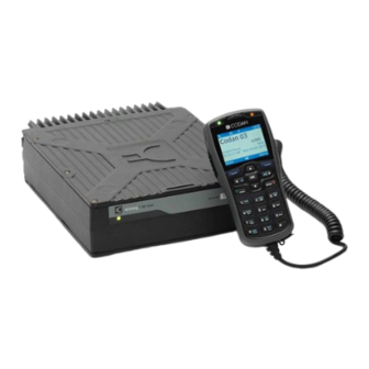
- Page 1 RADIO COMMUNICATIONS Envoy™ Transceiver Getting Started Guide...
- Page 2 Codan part number 15-04177-EN Issue 5, January 2015. CODAN™, Envoy™, Envoy™ SmartLink™, Easitalk™, CALM™, and TPS™ are trademarks of Codan Limited. Other brand, product, and company names mentioned in this document are trademarks or registered trademarks of their respective holders.
-
Page 3: Table Of Contents
ABLE OF CONTENTS Table of contents Section 1 Introduction Overview of this guide ....1 The 2220 Handset ..... . 3 The 2221 Handset . - Page 4 ABLE OF CONTENTS Section 3 Operating the transceiver Switching the transceiver on and off ... . . 32 Switching on the transceiver ....32 Switching off the transceiver .
- Page 5 ABLE OF CONTENTS Viewing the details of a waypoint ... . 82 Viewing GPS information ....82 Data options .
- Page 6 Cables in a fixed station ....164 Mounting a fixed Envoy™ station ... 164 Connecting a fixed Envoy™ station ..165 Earthing the transceiver .
- Page 7 ABLE OF CONTENTS Earth symbols ..... . 178 FCC compliance ..... . 179 FCC Part 90 certification .
- Page 8 ABLE OF CONTENTS This page has been left blank intentionally. ™ T NVOY RANSCEIVER ETTING TARTED UIDE...
- Page 9 IST OF FIGURES List of figures Figure 1: 2220 Handset ....... . 3 Figure 2: 2221 Handset .
- Page 10 Figure 45: Structure of call information for a contact in the Envoy Transceiver ......154 Figure 46: Typical mobile station .
- Page 11 Cables for a typical mobile Envoy™ station ..157 Table 9: Cables for a typical fixed Envoy™ station ..164 Table 10: Specifications ......169 Table 11: Earth symbols .
- Page 12 IST OF TABLES This page has been left blank intentionally. ™ T NVOY RANSCEIVER ETTING TARTED UIDE...
-
Page 13: Introduction
Overview of this guide This guide provides instructions on how to connect up your Envoy Transceiver, and how to perform basic setup and operating tasks. It assumes that you have limited knowledge of HF communication and of using an HF transceiver. - Page 14 NTRODUCTION VERVIEW OF THIS GUIDE Navigating the menu structure—describes how to navigate the menu structure and perform basic selection and editing functions Structure of information—describes the building blocks of information in the transceiver Installing the transceiver—describes how to mount and connect the transceiver in mobile and fixed stations Specifications—provides a list of specifications for the transceiver Compliance—provides mandatory compliance information...
-
Page 15: The 2220 Handset
NTRODUCTION 2220 H ANDSET The 2220 Handset The 2220 Handset is a control point for the Envoy Transceiver. The user interface provides an icon-based menu structure for easy setup and operation of the transceiver. Figure 1: 2220 Handset Power key... - Page 16 Handsets with a Mk 2 label on the rear escutcheon are compatible with all transceiver configurations, and are specifically designed to provide a received audio signal for an Envoy SmartLink. Mk 2 handsets are identified in Information > Device Information > Hardware Options as Mk 2 (Envoy SmartLink enabled).
-
Page 17: The 2221 Handset
ANDSET The 2221 Handset The 2221 Handset is a control point for the Envoy Transceiver. The user interface provides an icon-based menu structure for easy operation of the transceiver. It has a condensed set of keys for use in simpler communication scenarios. - Page 18 Handsets with a Mk 2 label on the rear escutcheon are compatible with all transceiver configurations, and are specifically designed to provide a received audio signal for an Envoy SmartLink. Mk 2 handsets are identified in Information > Device Information > Hardware Options as Mk 2 (Envoy SmartLink enabled).
-
Page 19: The 2230 Desk Console
ONSOLE The 2230 Desk Console The 2230 Desk Console is a control point for the Envoy Transceiver. The user interface provides an icon-based menu structure for easy setup and operation of the transceiver. The desk console is standard for a fixed station. -
Page 20: Keypad
NTRODUCTION EYPAD Keypad Standard macros are programmed in the transceiver in the factory. You can also create a macro and assign it to a hot key. NOTE: For more information, please see the Reference Manual. Table 1: Keys and their function Function Switches on the transceiver. - Page 21 NTRODUCTION EYPAD Table 1: Keys and their function (cont.) Function Reduces the volume when the indicator is shown in the menu bar of the screen. Scrolls right in a list of values. Moves the cursor/highlight to the right. Increases the volume when the indicator is shown in the menu bar of the screen.
- Page 22 NTRODUCTION EYPAD Table 1: Keys and their function (cont.) Function Enters 1 in character-entry mode. TUNE Tunes the antenna. Enters 2, a, b, c, A, B, C in character-entry mode for English, or other characters as per the selected input language.
- Page 23 NTRODUCTION EYPAD Table 1: Keys and their function (cont.) Function Enters 7, p, q, r, s, P, Q, R, S in character-entry mode for English, or other characters as per the selected input language. Toggles the type of mute selected. Enters 8, t, u, v, T, U, V in character-entry mode for English, or other characters as per the selected input language.
- Page 24 NTRODUCTION EYPAD Table 1: Keys and their function (cont.) Function Toggles character-entry mode. Enables you to select the input language (hold for 2 sec). Toggles between a top-level channel group and the channels within. Enables you to select a channel group (hold for 2 sec).
-
Page 25: Standards And Icons
NTRODUCTION TANDARDS AND ICONS Standards and icons The following standards and icons are used: This typeface... Means... Italic text requiring emphasis, or variable information Bold a key on a computer keyboard Bold a menu, submenu, tab, entry, a value in the user interface of the control point, or key that you press on the control point the user interface of the control point must be at... - Page 26 NTRODUCTION TANDARDS AND ICONS This page has been left blank intentionally. ™ T NVOY RANSCEIVER ETTING TARTED UIDE...
-
Page 27: Using The Wizard
Using the wizard This section contains the following topics: • Overview of the wizard on page 16 • Using the wizard on page 18 • Selecting a language on page 19 • Setting the time and date on page 19 •... -
Page 28: Overview Of The Wizard
SING THE WIZARD VERVIEW OF THE WIZARD Overview of the wizard The wizard is available if the transceiver: • has not been programmed with a profile • has a basic profile that has the same self address for each of the default HF networks: Selcall and CALM •... -
Page 29: Figure 4: Steps In The Wizard
SING THE WIZARD VERVIEW OF THE WIZARD Figure 4: Steps in the wizard ™ T NVOY RANSCEIVER ETTING TARTED UIDE... -
Page 30: Using The Wizard
SING THE WIZARD SING THE WIZARD Using the wizard The wizard should start automatically when a new transceiver is powered up for the first time. Figure 5: Wizard Startup screen NOTE: If the wizard screen doesn’t launch automatically, follow the instructions below. If your transceiver has been profiled using the TPS System Programmer, the wizard may not be available. -
Page 31: Selecting A Language
SING THE WIZARD SING THE WIZARD Highlight the icon for the wizard ( ), then press (OK). If the icon is not visible, then the wizard is not available as the transceiver has been programmed already with a non-basic profile. Press (Yes) to confirm that you want to start the wizard. - Page 32 SING THE WIZARD SING THE WIZARD Press (Save) to save the local time. to move to the Local Date entry. Press Press to enter edit mode for the local date. Press to scroll to the value that you want to set, then press to move to the next item.
-
Page 33: Setting The Types Of Connections Between Modules
Setting the types of connections between modules NOTE: This step in the wizard is shown if your control point is a desk console, or a Mk 2 handset connected via an Envoy SmartLink. The types of cables used to connect the modules in your system affect whether or not the control point can power down and power up the RFU. - Page 34 SING THE WIZARD SING THE WIZARD Enter the receive frequency (in kHz, with up to three decimal points or 1 Hz resolution), if required to be different from the Tx frequency. to move to the Mode entry. Press To select a mode: •...
-
Page 35: Entering A Self Address
SING THE WIZARD SING THE WIZARD Do one of the following: • If you want to scan all of the channels in the transceiver that have a USB mode, press (Yes), then continue from Entering a self address on page •... -
Page 36: Adding A Contact
SING THE WIZARD SING THE WIZARD NOTE: The wizard automatically allocates this self address to the default HF networks: Selcall and CALM (if FED-STD-1045 ALE or MIL-STD-188-141B ALE option is installed). Do one of the following: • If you want to add a contact, press (Yes), then continue from Adding a contact on page... - Page 37 SING THE WIZARD SING THE WIZARD If you are adding: • a Selective, Channel Test, Emergency, Get Position or Send Position call, continue from Adding a simple call on page 25 • a Message call, continue from Adding a Message call on page 26 •...
- Page 38 SING THE WIZARD SING THE WIZARD Adding a Message call To continue with adding a Message call: to move to the Selcall|ALE Address entry. Press Enter the address of the station that you want to call. to move to the Message entry, then press Press NOTE: If you want to be prompted to enter a message at...
- Page 39 SING THE WIZARD SING THE WIZARD • Press to scroll to the message that you want to use. NOTE: If you want to view the message, press (Details) to view the message, then press (Close). Press OK to select the message. •...
- Page 40 SING THE WIZARD SING THE WIZARD Adding a Phone call To continue with adding a Phone call: to move to the Phone Number entry. Press Enter the phone number. Continue from Completing the contact on page Completing the contact To finish entering the information required for the contact: Press to move to the Call Description entry.
-
Page 41: Selecting An Antenna
SING THE WIZARD SING THE WIZARD Selecting an antenna Each type of antenna has a specific requirement for tuning, and the transceiver uses a different protocol for each one. You must select the type of antenna that is used in your station so that the transceiver knows how to tune the antenna. -
Page 42: Selecting A Peripheral Device
NOTE: Codan peripheral devices are listed by their type number, for example, 3031 Crosspatch. The type number for a Codan device is located on the front or serial number escutcheon. To select a peripheral device: Press to scroll to the type of peripheral device that is attached to the connector, then press OK. -
Page 43: Operating The Transceiver
Operating the transceiver This section contains the following topics: • Switching the transceiver on and off on page 32 • The channel screen on page 33 • Selecting a channel on page 37 • Selecting a channel from a channel group on page 38 •... -
Page 44: Switching The Transceiver On And Off
PERATING THE TRANSCEIVER WITCHING THE TRANSCEIVER ON AND OFF Switching the transceiver on and off Switching on the transceiver To switch on the transceiver: Press The template screen, then the welcome screen (if set) are shown briefly, followed by the channel screen. Switching off the transceiver The power-down function controls which modules are switched off. -
Page 45: The Channel Screen
PERATING THE TRANSCEIVER HE CHANNEL SCREEN The channel screen The channel screen shows the following information: • the name of the currently selected channel NOTE: If ... is shown before the channel name, then this channel is contained within a channel group. •... -
Page 46: Figure 6: Channel Screen
PERATING THE TRANSCEIVER HE CHANNEL SCREEN Figure 6: Channel screen mute type signal indicator strength Tx power call type (highlighted indicator setting icon when mute is on) missed call icon Rx/Tx indicator mode status bar channel name Tx/Rx frequency status areas menu bar left software key right software key... -
Page 47: Figure 7: System Lock And Connected Data Application Icons
PERATING THE TRANSCEIVER HE CHANNEL SCREEN Your transceiver may have the option of selecting high, medium, or low power, as set in Settings > Configuration > Tx Power. By default, you can toggle between the Tx power settings by pressing the 6 key. Hi, Med, or Lo is shown respectively to the right of the signal strength indicator. -
Page 48: Figure 8: Scanning Screen
PERATING THE TRANSCEIVER HE CHANNEL SCREEN Figure 8: Scanning screen scan indicator ™ T NVOY RANSCEIVER ETTING TARTED UIDE... -
Page 49: Selecting A Channel
PERATING THE TRANSCEIVER ELECTING A CHANNEL Selecting a channel To select a channel: Press PTT to exit to the channel or scanning screen. If the transceiver is scanning, press SCAN to switch off scanning. Press to scroll to the channel that you want to use. The channel is selected. -
Page 50: Selecting A Channel From A Channel Group
PERATING THE TRANSCEIVER ELECTING A CHANNEL FROM A CHANNEL GROUP Selecting a channel from a channel group If channel grouping is enabled in Settings > Control Point > Channel Grouping and you have allocated channels to groups, indicated by ... after a channel group name or in front of the channel name, you may have to switch to another channel group to find the channel that you want to select. - Page 51 PERATING THE TRANSCEIVER ELECTING A CHANNEL FROM A CHANNEL GROUP If you are within a channel group but the channel that you want is not visible, do one of the following: • Press to move to the channel group level, press to scroll to the channel group that you want, then press •...
- Page 52 PERATING THE TRANSCEIVER ELECTING A CHANNEL FROM A CHANNEL GROUP Do any of the following: Hold OK to edit the channel, if permitted. • Press OK to search for a channel. • Press CALL to start a call. • Hold CALL to go to Contacts. •...
-
Page 53: Scanning Channels
PERATING THE TRANSCEIVER CANNING CHANNELS Scanning channels If you intend to receive calls on several channels, switch on scanning. When scanning is switched on, the transceiver sequentially selects each channel/mode in your scan tables to detect incoming calls. The channels are scanned in a continuous cycle. -
Page 54: Switching Scanning On Or Off
PERATING THE TRANSCEIVER CANNING CHANNELS Switching scanning on or off To switch scanning on or off: Press SCAN. If a call is not in progress, scanning is toggled on or off. If a call is in progress, the call is ended and the transceiver begins scanning. - Page 55 PERATING THE TRANSCEIVER CANNING CHANNELS While scanning is paused, do one of the following: • To speak on the selected channel, hold down PTT. To resume scanning immediately, press OK. • To stop scanning completely, press SCAN. • ™ T NVOY RANSCEIVER ETTING...
-
Page 56: Muting The Transceiver
PERATING THE TRANSCEIVER UTING THE TRANSCEIVER Muting the transceiver When the transceiver is set to a channel or is scanning channels, and mute is switched off, you hear on-air signals on each channel. If you do not want to listen to this, you can silence the transceiver by switching on mute. -
Page 57: Selecting The Mute Type
PERATING THE TRANSCEIVER UTING THE TRANSCEIVER Selecting the mute type To select the mute type: If you are using a 2220 Handset or 2230 Desk Console, press to toggle the mute type between selcall mute (S) and voice mute (V). If you are using a 2221 Handset: •... -
Page 58: Using The Microphone
CAUTION: Your conversation can be monitored by anyone tuned to your transmit frequency, unless you are using one of Codan’s encryptors. Your signal can potentially travel very large distances. If PTT is held continuously for a certain length of time, the system stops transmission, switches to receive and shows an error message on the control point. -
Page 59: Setting The Basics
PERATING THE TRANSCEIVER ETTING THE BASICS Setting the basics Setting the time and date The transceiver is set to UTC time in the factory. You set the local time and time zone for the location of the control point. This feature is useful if you have a communication network that spreads over several time zones, or you need to time stamp your transmissions according to the current time at longitude zero. -
Page 60: Setting The Brightness Of The Display
PERATING THE TRANSCEIVER ETTING THE BASICS Press to select the type of clock that you want to use. to move to the Time Format entry. Press Press to select the format that you want to use. to move to the Date Format entry. Press Press to select the format that you want to use. -
Page 61: Calling
PERATING THE TRANSCEIVER ALLING Calling This section describes how to make the various types of calls from the transceiver. You can make a call to a contact, return or repeat a call from the Call History, or enter information at the time of the call. For selective calling in ALE/CALM and Selcall HF networks, a control point must register a self address from the list of available addresses for that HF network. -
Page 62: Making A Call To A Contact
PERATING THE TRANSCEIVER ALLING Making a call to a contact NOTE: The default behaviour for the CALL key is to press it to start a call, or hold CALL to see your Contacts/Call History. This behaviour may be reversed by your system administrator, if required. -
Page 63: Making A Call From The Call History
Making a call from the Call History The Envoy Transceiver stores information for up to 200 calls that have been sent and received for a control point. Each control point may store this call information for up to 20 RFUs to which it has been connected. - Page 64 PERATING THE TRANSCEIVER ALLING NOTE: A filtered Call Log is available in the call screen. This log contains only the latest instance of a call to and from a specific station, and provides records of up to 20 calls. NOTE: Missed calls are indicated by an exclamation mark in a yellow triangle in front of the call icon.
-
Page 65: Making A Call From The Emergency Key
PERATING THE TRANSCEIVER ALLING Press to select the call type that you want to use. Continue from making your chosen call type. Related links: Viewing missed calls on page 61 Making a call from the Emergency key You can set up an emergency contact with calls that are chained together when you hold the key. -
Page 66: Making A Selective Call
PERATING THE TRANSCEIVER ALLING Figure 9: Chain call number of calls total number of calls completed set up in the chain call countdown to next call Making a Selective call If you want to speak with the operator at a particular station, make a Selective call to the address of that station. - Page 67 PERATING THE TRANSCEIVER ALLING If you do not want to use the HF network shown at the top right of the screen: • Press (Options). Scroll to HF Networks, then press • (Select). • Scroll to the HF network that you want to use, then press OK.
-
Page 68: Making A Message Call
PERATING THE TRANSCEIVER ALLING If prompted, press to scroll to the channel that you want to use, then press CALL. is shown next to the currently selected channel/mode. To abort the call before it is answered, press PTT or SCAN. There will be audible beeps or a pop-up message to indicate that the call has been successful. - Page 69 PERATING THE TRANSCEIVER ALLING If you do not want to use the HF network shown at the top right of the screen: • Press (Options). Scroll to HF Networks, then press • (Select). • Scroll to the HF network that you want to use, then press OK.
- Page 70 PERATING THE TRANSCEIVER ALLING If you want to enter a message: • Hold to select a different input language, if required. • Start typing the message. NOTE: Press OK to start a new line, if required. (Options), scroll to OK, then press •...
- Page 71 PERATING THE TRANSCEIVER ALLING (Options), scroll to OK, then press • Press (Select). If prompted, press to scroll to the channel that you want to use, then press CALL. is shown next to the currently selected channel/mode. To abort the call before it is answered, press PTT or SCAN. There will be audible beeps or a pop-up message to indicate that the call has been successful.
-
Page 72: Receiving A Call
PERATING THE TRANSCEIVER ALLING Receiving a call Some calls that are addressed to your station are handled automatically by your transceiver. It will either respond automatically with the information requested in the call that it received (Get Position, Get Status, Channel Test, or ALE Sounding call), or receive the message (Message or Send Position call). -
Page 73: Viewing Missed Calls
PERATING THE TRANSCEIVER ALLING NOTE: Depending on the setup of the HF network used for the call and the digital voice and/or encryption options installed in the transceiver, the transceiver may switch automatically between analogue/digital voice and/or clear/secure signals. If you are receiving a Selective or Emergency call, answer the call by holding PTT and speaking side-on across the microphone in the handset, or directly into the microphone on the desk console. -
Page 74: Figure 11: Missed Call Pop-Up For A Single Call
PERATING THE TRANSCEIVER ALLING Figure 11: Missed call pop-up for a single call Figure 12: Missed call pop-up for multiple calls Figure 13: Example of a missed call icon in the status bar of the channel screen NOTE: Received Get Status and Get Position calls, which do not present an incoming call pop-up, are not tracked as missed calls. -
Page 75: Table 2: Missed Call Icons That May Be Shown In The Status Bar Of The Channel Screen
PERATING THE TRANSCEIVER ALLING Table 2: Missed call icons that may be shown in the status bar of the channel screen Icon Description At least one missed or unread Emergency call exists (takes priority over all other missed calls) At least one missed Selective, Phone, ALL, ANY, Group Selective or Wildcard call exists (voice-type call) At least one unread Message or Send Position call exists (received message-type call) -
Page 76: Making A Call When Multiple Control Points Are Connected To The Same Rfu
PERATING THE TRANSCEIVER ALLING Press to scroll through the details of the missed call. Press (Close). If you want to return a missed call, scroll to the call, press CALL, then continue with the call. Making a call when multiple control points are connected to the same RFU When multiple control points are connected to the same RFU and a call is made, certain activities may be excluded if the control point does not... -
Page 77: Figure 14: Calling Information When Multiple Control
PERATING THE TRANSCEIVER ALLING Figure 14: Calling information when multiple control points are connected control point with control point without control of a call control of a call You may be able to override this lock, depending on the value set in Settings >... -
Page 78: Using Digital Voice
PERATING THE TRANSCEIVER SING DIGITAL VOICE Using digital voice Overview of digital voice options Digital voice is now offered through two distinct methods. The latest method offers digital voice with or without MIL/STANAG 2G Data, and with or without an AES-256 Encryption upgrade; these are referred to as the DV options with/without an AES-256 Encryption upgrade. -
Page 79: Table 4: Digital Voice Rates
PERATING THE TRANSCEIVER SING DIGITAL VOICE Table 3: Digital voice options (cont.) Sales option Encryptor When the When the type Icon digital voice digital voice option is option is inactive... active... AES-256 DV AES-256 Analogue voice Secure digital Encryptor voice (15-10565) Related links: Using encryption on page 100... -
Page 80: Figure 15: Channel Screen Showing The Digital Voice Rate
PERATING THE TRANSCEIVER SING DIGITAL VOICE NOTE: The 600 bit/s and 1200 bit/s rates are available as sales options for the DV options (with or without encryption). The AES-256 DV Encryptor has standard data rates of 1200 bit/s and 2400 bit/s. Figure 15: Channel screen showing the digital voice rate Active DV option without All active encrypted... -
Page 81: Switching The Digital Voice Feature On Or Off
PERATING THE TRANSCEIVER SING DIGITAL VOICE Figure 16: Digital voice mute indicator Digital voice mute indicator DV option without AES-256 All encrypted digital voice (in Tx) Encryption upgrade (in Tx) Related links: Selecting digital voice mute on page 73 Switching the digital voice feature on or off To switch the digital voice feature on or off: If you are using a 2220 Handset or 2230 Desk Console, press... -
Page 82: Figure 17: Channel Screen Showing On/Off Status For A Dv Option (Without Encryption)
PERATING THE TRANSCEIVER SING DIGITAL VOICE Figure 17: Channel screen showing on/off status for a DV option (without encryption) Digital voice (in Rx) Analogue voice (in Rx) icon for digital voice DV option data rate Figure 18: Channel screen showing transmit/receive status for a DV option (without encryption) Transmit (digital voice active) Receive (digital voice active) -
Page 83: Figure 19: Channel Screen Showing Secure/Clear Status For All Encrypted Digital Voice
PERATING THE TRANSCEIVER SING DIGITAL VOICE CAUTION: When transmitting with the AES-256 DV Encryptor, you should hold PTT, wait 2 sec, speak, wait 2 sec, then release PTT. If you have a DV option with the AES-256 Encryption upgrade installed, or you have the AES-256 DV Encryptor installed, the transceiver will also go secure/clear when is pressed. -
Page 84: Selecting The Digital Voice Rate
PERATING THE TRANSCEIVER SING DIGITAL VOICE Selecting the digital voice rate The digital voice rate sets the speed with which digital voice transmissions are sent. The digital voice rate is shown in status area 1 of the screen. Use the lowest digital voice rate in the first instance, then if good HF propagation conditions exist, a higher rate may be selected. -
Page 85: Selecting Digital Voice Mute
PERATING THE TRANSCEIVER SING DIGITAL VOICE Press to select the digital voice rate that you want to use. Press (OK). Related links: Digital voice rate on page 67 Selecting digital voice mute NOTE: Digital voice mute is available when a DV option (with or without the AES-256 Encryption upgrade) or the AES-256 DV Encryptor is active, and scanning is switched off or paused. - Page 86 PERATING THE TRANSCEIVER SING DIGITAL VOICE DV option without AES-256 Encryption upgrade (in Tx) All encrypted digital voice (in Tx) Related links: Digital voice mute on page 68 ™ T NVOY RANSCEIVER ETTING TARTED UIDE...
-
Page 87: Using Gps
PERATING THE TRANSCEIVER SING Using GPS Saving your current GPS position as a waypoint To save your current GPS position as a waypoint: Do one of the following: Press 9| • • From the main menu, select (General), then (GPS). Press (Save). -
Page 88: Updating A Waypoint From The Call History
PERATING THE TRANSCEIVER SING Updating a waypoint from the Call History You can update a waypoint using information from a Get Position call or a received Send Position call in the Call History. If you do not want to use the waypoint information immediately, you may save it. Waypoints that are saved via the Distance and Bearing tab are automatically added to the Waypoints tab at the same location, and to the list of waypoints in User Data >... -
Page 89: Updating A Waypoint From A Contact
PERATING THE TRANSCEIVER SING If you want to save the GPS information as a waypoint: (Options), scroll to Save, then press • Press (Select). • Enter the name that you want to use for the waypoint. NOTE: If required, you can change the GPS information. - Page 90 PERATING THE TRANSCEIVER SING Press to scroll to the contact whose GPS information you want to use for the waypoint. (Options), scroll to Call, then press Press (Select). If prompted, select a channel, then press OK. The GPS information appears in an incoming call pop-up. Press OK.
-
Page 91: Adding A Waypoint
PERATING THE TRANSCEIVER SING Press (Close). Adding a waypoint You can create a waypoint by entering GPS information and providing it with a meaningful name. The waypoint can be saved for future use. To add a waypoint: Do one of the following: Press 9| •... - Page 92 PERATING THE TRANSCEIVER SING Do one of the following: • If there are no waypoints programmed in the transceiver, press (Add). • If there are some existing waypoints programmed in the transceiver, scroll to the waypoint after which you want to add the new waypoint, press (Options), scroll to Add, then press...
-
Page 93: Finding A Waypoint
PERATING THE TRANSCEIVER SING Finding a waypoint To find a waypoint: Do one of the following: Press 9| • • From the main menu, select (General), then (GPS). to move to the Distance and Bearing tab. Press Press (Waypoint). Press to select the tab in which you want to search. -
Page 94: Viewing The Details Of A Waypoint
PERATING THE TRANSCEIVER SING Viewing the details of a waypoint To view the details of a waypoint: Do one of the following: Press 9| • • From the main menu, select (General), then (GPS). Press to move to the Distance and Bearing tab. Press (Waypoint). -
Page 95: Table 5: Gps Information
PERATING THE TRANSCEIVER SING NOTE: The Signal Strength and Satellites Constellation tabs are available only when a GPS receiver is used to provide the GPS information. Table 5: GPS information Description Shows the latitude and longitude readings from a GPS receiver, or from Settings >... - Page 96 PERATING THE TRANSCEIVER SING Table 5: GPS information (cont.) Description Shows the signal strength from each visible satellite. The number represents a particular satellite, and its location is shown on the Satellites Constellation tab. Satellites with a blue signal strength provide information for the GPS location.
-
Page 97: Data Options
UUPlus©, please see the documentation provided with the product. Typical 2.4 kbit/s data station A typical data station comprises: • an Envoy X2 Transceiver with the 2.4 kbit/s Data Modem option enabled (Codan part number 15-10559) • a suitable 12 V DC power supply •... -
Page 98: Figure 21: Envoy X2 Transceiver With 2.4 Kbit/S Data Modem Option And Computer
PERATING THE TRANSCEIVER ATA OPTIONS Figure 21: Envoy X2 Transceiver with 2.4 kbit/s Data Modem option and computer i t h i t / s 2 . 4 ™ 4 - 0 ri a - 0 7 i c r... - Page 99 PERATING THE TRANSCEIVER ATA OPTIONS CAUTION: Data transmitted via a VCOM session over a USB–USB connection may be affected by your computer’s power-saving activities. Either disable the power-saving mode while data is being transmitted, or verify that the data has been sent correctly when the computer wakes from power-saving mode.
-
Page 100: Table 6: Status Of The 2.4 Kbit/S Data Modem
PERATING THE TRANSCEIVER ATA OPTIONS Viewing the performance of the 2.4 kbit/s Data Modem You can set one of the status areas to show the link status and throughput of the internal data modem. To view the performance of the modem: Go to the channel screen. - Page 101 PERATING THE TRANSCEIVER ATA OPTIONS Table 6: Status of the 2.4 kbit/s Data Modem (cont.) Colour of State Description Green Flashing The station is establishing a link, or in a link, with another station. This station is the receiver of the link. Flashing The station is establishing a link, or in a link, with another station.
- Page 102 PERATING THE TRANSCEIVER ATA OPTIONS Table 6: Status of the 2.4 kbit/s Data Modem (cont.) Colour of State Description Red (bar) Variable Red bar is indicative of the data throughput rate for length the link. Grey Solid The modem is enabled in the firmware, but a computer is not connected and/or not communicating with it.
-
Page 103: Mil/Stanag 2G Data
Related links: Using encryption on page 100 Typical MIL/STANAG 2G data station A typical MIL/STANAG 2G data station comprises: • an Envoy X2 Transceiver with MIL/STANAG 2G Data option • an antenna system • an appropriate 12 V DC power supply •... -
Page 104: Figure 22: Envoy X2 Transceiver With Mil/Stanag
PERATING THE TRANSCEIVER ATA OPTIONS Figure 22: Envoy X2 Transceiver with MIL/STANAG 2G Data via serial cable I L / S r f a w i t n t e t a I 2 2 1 ™ ri a s e e... -
Page 105: Figure 23: Envoy X2 Transceiver With Mil/Stanag 2G Data Via Vcom Over Usb Cable
PERATING THE TRANSCEIVER ATA OPTIONS Figure 23: Envoy X2 Transceiver with MIL/STANAG 2G Data via VCOM over USB cable I L / S r f a w i t n t e t a I 2 2 1 o l e... -
Page 106: Figure 24: Envoy X2 Transceiver With Mil/Stanag 2G Data Via Vcom Over Ethernet Cable
PERATING THE TRANSCEIVER ATA OPTIONS Figure 24: Envoy X2 Transceiver with MIL/STANAG 2G Data via VCOM over Ethernet cable I L / S r f a w i t n t e t a I 2 2 1 ™ ri a... - Page 107 PERATING THE TRANSCEIVER ATA OPTIONS CAUTION: When VCOM is used over an Ethernet cable, the RFU 6way MIL/STANAG 2G Data and RFU 15way MIL/STANAG 2G Data peripheral devices must not be selected on the respective ports. NOTE: For information on setting up the data station, please see the Reference Manual.
-
Page 108: Rm50E Hf Data Modem
The RM50e HF Data Modem provides data communications. It may also be used to provide high-grade AES-256 digital encryption. It may be used with any data-capable Codan HF transceiver. It must be used in conjunction with the RC50-C HF Email software. The data modem is capable of high-speed data transfer at speeds of up to 9600 bit/s using STANAG 4539 waveforms. -
Page 109: Figure 26: Envoy X2 Transceiver With Rm50E Hf Data
12 V DC power supply • an RM50e HF Data Modem, selected as a peripheral device • a computer with RC50-C HF Email software Figure 26: Envoy X2 Transceiver with RM50e HF Data Modem - 0 7 7 - 0 ™... - Page 110 PERATING THE TRANSCEIVER ATA OPTIONS NOTE: For more information on setting up and using an RM50e email station, please see the documentation provided with the modem and the RC50-C on-line help. Sending email via RC50-C An email message is sent via your email client to the RC50-C HF Email software, which passes it to the RM50e.
-
Page 111: Figure 27: Transmit And Receive Screens During An Rm50E
PERATING THE TRANSCEIVER ATA OPTIONS Figure 27: Transmit and receive screens during an RM50e data call Transmit Receive Related links: Using encryption on page 100 ™ T NVOY RANSCEIVER ETTING TARTED UIDE... -
Page 112: Using Encryption
PERATING THE TRANSCEIVER SING ENCRYPTION Using encryption You may have access to encryption/scrambling if these options are enabled in your transceiver, and appropriate hardware fitted, if required. Switching the secure feature on or off The 2220 Handset and 2230 Desk Console have a hot key that accesses the secure feature directly. - Page 113 PERATING THE TRANSCEIVER SING ENCRYPTION For CIVS voice scrambling you will see: Secure (in Rx) Clear (in Rx) privacy code Transmit (while secure) Receive (while secure) ™ T NVOY RANSCEIVER ETTING TARTED UIDE...
- Page 114 PERATING THE TRANSCEIVER SING ENCRYPTION For CES-128 voice encryption you will see: Secure (in Rx) Clear (in Rx) secure index for CES-128 secure key Transmit (while secure) Receive (while secure) ™ T NVOY RANSCEIVER ETTING TARTED UIDE...
- Page 115 PERATING THE TRANSCEIVER SING ENCRYPTION For AES-256 digital voice you will see: Secure (in Rx) Clear (in Rx) digital secure index digital voice key prefix for AES-256 data rate secure key Transmit (while secure) Receive (while secure) ™ T NVOY RANSCEIVER ETTING TARTED...
- Page 116 PERATING THE TRANSCEIVER SING ENCRYPTION For AES-256 data encryption you will see: Secure (in Rx) Clear (in Rx) digital secure index for key prefix AES-256 data secure key Transmit (while secure) Receive (while secure) NOTE: If you have more than one encryptor/scrambler available for activation, you can change to another encryptor/scrambler, if permitted.
- Page 117 PERATING THE TRANSCEIVER SING ENCRYPTION Standby If you are using CES-128 voice encryption with a 2221 Handset, do the following to go to secure standby mode: • Press (Options). to scroll to the Standby On option. • Press • Press (Select).
-
Page 118: Selecting A Secure Key
PERATING THE TRANSCEIVER SING ENCRYPTION If you are using a 2221 Handset: • From the main menu, select (Functions). to scroll to the Secure Info entry. • Press • Press (Select). Enter up to 4 digits. Press (Activate). The transceiver goes secure on the selected key. Selecting a secure key If an encryptor contains two or more keys, you have the option of selecting a different key for encryption, if permitted. -
Page 119: Changing The Privacy Code
PERATING THE TRANSCEIVER SING ENCRYPTION If you are using a 2221 Handset: • From the main menu, select (Functions). to scroll to the Secure Info function. • Press • Press (Select). to scroll to the Select Key Index entry. Press Press to select the secure key index that you want to use. -
Page 120: Adding A Secure Key
The transceiver goes secure on the selected code. Adding a secure key NOTE: Codan’s KMS may be used to generate secure keys and to fill the CES and AES DV and data encryptors. KFS may be used to fill keys to these encryptors. - Page 121 PERATING THE TRANSCEIVER SING ENCRYPTION NOTE: AES-256 DV and data encryptors use the same secure key. To add a secure key: If you are using a 2220 Handset or 2230 Desk Console, do one of the following: • From the main menu, select (General), then (Secure).
- Page 122 PERATING THE TRANSCEIVER SING ENCRYPTION Enter the characters that you want to use for the secure key. Press (Save) to save the information. Press (Close). ™ T NVOY RANSCEIVER ETTING TARTED UIDE...
-
Page 123: Using A Crosspatch
PERATING THE TRANSCEIVER SING A CROSSPATCH Using a crosspatch Overview of the 3031 Crosspatch The 3031 Crosspatch is a device that connects an HF communication system with a VHF or UHF communication system. NOTE: The use of the CIVS voice scrambler is not recommended across VHF/UHF to HF communication links. -
Page 124: Figure 28: Crosspatch Status
PERATING THE TRANSCEIVER SING A CROSSPATCH Figure 28: Crosspatch status crosspatch indicator crosspatch state crosspatch indicator Active crosspatch state crosspatch indicator Standby crosspatch state If the crosspatch is selected as the peripheral device for the 15-way connector, but has been disconnected, the crosspatch indicator is no longer shown in the status bar of the channel screen. -
Page 125: Changing The Operating Mode Of The Crosspatch
PERATING THE TRANSCEIVER SING A CROSSPATCH Changing the operating mode of the crosspatch To change the operating mode of the crosspatch: If you are using a 2220 Handset or 2230 Desk Console, press 5. If you are using a 2221 Handset: •... -
Page 126: Upgrading The Transceiver Via A Usb Stick
RFU is busy. To manage profiles, firmware, and secure keys: Connect your USB stick to the control point using a standard USB A (female) to micro USB cable (Codan part number 67-90406). The USB stick is detected automatically. A Select Task icon ( ) is now available in the main menu screen. - Page 127 PERATING THE TRANSCEIVER PGRADING THE TRANSCEIVER VIA A STICK Do one of the following: • Press to scroll to the profile, firmware package, (Options), scroll to Open, or key set file, press then press (Select). • Press to scroll to the folder in which you want to save the profile from the transceiver, then press (Save).
- Page 128 PERATING THE TRANSCEIVER PGRADING THE TRANSCEIVER VIA A STICK This page has been left blank intentionally. ™ T NVOY RANSCEIVER ETTING TARTED UIDE...
- Page 129 Contacts This section contains the following topics: • Adding a contact on page 118 • Adding a contact from the Call Log, Call History, or Last Heard Log on page 125 ™ T NVOY RANSCEIVER ETTING TARTED UIDE...
-
Page 130: Adding A Contact
ONTACTS DDING A CONTACT Adding a contact Contacts are used to pre-define the typical calls that you want to make to another person or organisation, and calls that are made to an emergency contact when the key is held for 2 sec. To add a contact: (User Data), then From the main menu, select... -
Page 131: Adding A Simple Call
ONTACTS DDING A CONTACT Press to select the HF network that you want to use. to move to the Call Type entry. Press Press to select the call type that you want to use. NOTE: The call type that you select affects information that you can enter for the remainder of this call. -
Page 132: Adding A Message Call
ONTACTS DDING A CONTACT Adding a Message call To continue with adding a Message call: to move to the Selcall|ALE Address entry. Press Enter the address of the station that you want to call. to move to the Message entry, then press Press NOTE: If you want to be prompted to enter a message at... - Page 133 ONTACTS DDING A CONTACT If you want to select a message from a list of stored messages: (Options), scroll to Stored, then press • Press (Select). • Press to scroll to the message that you want to use. NOTE: If you want to view the message, press (Details) to view the message, then press...
-
Page 134: Adding A Phone Call
ONTACTS DDING A CONTACT Adding a Phone call To continue with adding a Phone call: to move to the Phone Link entry. Press NOTE: This entry is shown if there are two or more phone links from which to choose. Press to select the phone link that you want to use, or select <Prompt>... -
Page 135: Completing The Contact
ONTACTS DDING A CONTACT Completing the contact To finish entering the information required for the contact: to move to the Call Description entry. Press The call type is entered automatically as the call description. Enter a new description for this call, if required. Press (Save) to save the information. - Page 136 ONTACTS DDING A CONTACT To select a channel: • Press to view the list of available channels. • Press to scroll to the channel that you want to use, then press OK. is shown next to the channel/mode. • Press to change the mode, if required.
-
Page 137: Adding A Contact From The Call Log, Call History, Or Last Heard Log
ONTACTS DDING A CONTACT FROM THE ISTORY EARD Adding a contact from the Call Log, Call History, or Last Heard Log You can save information from the Call Log, Call History, or Last Heard Log to Contacts. This can either be a new call type for an existing contact, or you can add a new contact to hold this call information. - Page 138 ONTACTS DDING A CONTACT FROM THE ISTORY EARD To add a contact from the Call Log, Call History, or Last Heard Log: Do one of the following: Press CALL, then press • to scroll to the entry in the Call Log. Hold CALL, press (Call History), then •...
- Page 139 Navigating the menu structure This section contains the following topics: • The basic menu structure on page 128 • Navigating the menu structure on page 130 • Overview of basic and advanced views on page 132 • Finding a word or value on page 134 •...
-
Page 140: The Basic Menu Structure
AVIGATING THE MENU STRUCTURE HE BASIC MENU STRUCTURE The basic menu structure The menu structure comprises a main menu and a series of submenus that are accessed via the main menu. Each menu and submenu is represented by an icon. Some icons provide direct access to an input/view screen, while other icons provide a list of entries for the menu. -
Page 141: Figure 31: Menu Structure (User Level, Basic View)
AVIGATING THE MENU STRUCTURE HE BASIC MENU STRUCTURE Figure 31: Menu structure (user level, basic view) Setup Wizard User Data Channels Scan Tables HF Networks Contacts Peripherals Modes Waypoints Messages Settings Control Point Configuration Connectors Scan Calling Admin Login/Logout Advanced View Information Device Information Option Password... -
Page 142: Navigating The Menu Structure
AVIGATING THE MENU STRUCTURE AVIGATING THE MENU STRUCTURE Navigating the menu structure The menu structure comprises a main menu and a series of submenus that are accessed via the main menu. Navigation keys enable you to highlight an icon, then press OK to select that menu. You can continue drilling down through the menu structure in this way. - Page 143 AVIGATING THE MENU STRUCTURE AVIGATING THE MENU STRUCTURE NOTE: If the left-most icon is highlighted when you press , the highlight wraps to the last icon in the previous row of icons. Press OK. • • Continue moving down through the menu structure by highlighting the icon that you want, then pressing OK.
-
Page 144: Overview Of Basic And Advanced Views
AVIGATING THE MENU STRUCTURE VERVIEW OF BASIC AND ADVANCED VIEWS Overview of basic and advanced views There are two views of information in the user interface of the control point: basic and advanced. The contents of basic and advanced views are pre-determined and cannot be changed. -
Page 145: Switching Between Basic And Advanced Views
AVIGATING THE MENU STRUCTURE VERVIEW OF BASIC AND ADVANCED VIEWS Figure 34: Advanced view advanced view indicator Switching between basic and advanced views The user can switch between basic and advanced views to either: • simplify the user interface of the control point (basic view), or •... -
Page 146: Finding A Word Or Value
AVIGATING THE MENU STRUCTURE INDING A WORD OR VALUE Finding a word or value The quickest way to find an entry or a value in the user interface of the control point is to use the Find function, which is available via the key when the highlighted icon contains submenus or lists of entries. - Page 147 AVIGATING THE MENU STRUCTURE INDING A WORD OR VALUE NOTE: If you select the icon by pressing OK, you will enter that menu level. If you do not want to search at the lower level, press (Close) to return to the higher level, then press (Find) again.
- Page 148 AVIGATING THE MENU STRUCTURE INDING A WORD OR VALUE Press OK. You are taken to the entry, or the name level of the user data containing the character. ™ T NVOY RANSCEIVER ETTING TARTED UIDE...
-
Page 149: Selecting An Icon
AVIGATING THE MENU STRUCTURE ELECTING AN ICON Selecting an icon The top levels of the menu structure are represented by icons. In order to enter the menu represented by the icon, you need to select the icon. Figure 36: Highlighted icon highlighted icon To select an icon: to highlight the icon that you want to... -
Page 150: Selecting A Function From The Menu Bar
AVIGATING THE MENU STRUCTURE ELECTING A FUNCTION FROM THE MENU BAR Selecting a function from the menu bar The menu bar at the bottom of the screen provides varying functions, depending on the context. You can select a function directly, or activate a pop-up from the menu bar by pressing the corresponding key ( ). - Page 151 AVIGATING THE MENU STRUCTURE ELECTING A FUNCTION FROM THE MENU BAR If a pop-up of available functions is shown: • Press to scroll to the function that you want to select. • Press (Select). The function is performed. If you want to close the pop-up and not perform any of the functions, press the opposite software key (typically Close).
-
Page 152: Entering Text In A Field
AVIGATING THE MENU STRUCTURE NTERING TEXT IN A FIELD Entering text in a field You may need to enter text into a field within an entry. This may be a name given to some user data, or it may be a specific value, such as a frequency. -
Page 153: Figure 39: Character-Entry Mode Indicator
AVIGATING THE MENU STRUCTURE NTERING TEXT IN A FIELD Press repeatedly to select the character-entry mode that you want to use. The indicator for the character-entry mode is shown in the centre of the menu bar. NOTE: The character-entry mode indicators are specific to each language selection. - Page 154 AVIGATING THE MENU STRUCTURE NTERING TEXT IN A FIELD Do any of the following: • Press to move the cursor to the point at which you want to enter text. (on SCAN key) to delete text to the left of the •...
-
Page 155: Entering A Special Character (2220/2230)
AVIGATING THE MENU STRUCTURE NTERING TEXT IN A FIELD Entering a special character (2220/2230) You can enter special characters in messages, names, contacts, and in addresses of stations that you call. NOTE: If the FED-STD-1045 ALE/CALM option or MIL-STD-188-141B ALE option is installed in your transceiver, the key may be used to enter the global ALL address syntax (@?@) or special ALE addressing... -
Page 156: Entering Text With The 2221 Handset
AVIGATING THE MENU STRUCTURE NTERING TEXT IN A FIELD Entering text with the 2221 Handset The 2221 Handset does not have alphanumeric keys, however, you can still enter text into fields within the user interface. CAUTION: This process describes how to enter text into an entry field using the virtual keypad, then save the text back to the entry. - Page 157 AVIGATING THE MENU STRUCTURE NTERING TEXT IN A FIELD Press (Save) to save the information. You are returned to the entry. Continue with making changes to the item that you are editing, if required. ™ T NVOY RANSCEIVER ETTING TARTED UIDE...
-
Page 158: Selecting A Value From A List
AVIGATING THE MENU STRUCTURE ELECTING A VALUE FROM A LIST Selecting a value from a list When you select an entry that has a list of values, either by selecting an icon or using the navigation keys, the field is highlighted to show that it can be edited, and indicators appear on one or both sides of the field to show that multiple values are available. -
Page 159: Selecting/Deselecting A Check Box
AVIGATING THE MENU STRUCTURE ELECTING DESELECTING A CHECK BOX Selecting/deselecting a check box There are some entries in the menu structure that require you to enable or disable a particular feature via a check box. Figure 41: Entry with a check box To select or deselect a check box: Highlight the entry. -
Page 160: Moving A Slider
AVIGATING THE MENU STRUCTURE OVING A SLIDER Moving a slider Some values in the user interface of the control point are represented by a slider. Figure 42: A slider value slider navigation key indicator To move a slider: Press any of the navigation keys suggested in the navigation key indicator to adjust the slider. -
Page 161: Changing The Order Of Items In A List
AVIGATING THE MENU STRUCTURE HANGING THE ORDER OF ITEMS IN A LIST Changing the order of items in a list In some areas of the user interface of the control point, you are able to change the order in which items appear in a list, which impacts how the item is viewed, or when each item may be used. -
Page 162: Saving Your Changes
AVIGATING THE MENU STRUCTURE AVING YOUR CHANGES Saving your changes When information in an item has been changed, either by editing existing text or selecting a different value from a list, an asterisk is added to the title of the screen. Figure 43: Screen that has changes to be saved asterisk indicates that changes... -
Page 163: Structure Of Information
Structure of information This section contains the following topics: • Structure of user information on page 152 • Structure of contact and call information on page 154 ™ T NVOY RANSCEIVER ETTING TARTED UIDE... -
Page 164: Structure Of User Information
TRUCTURE OF INFORMATION TRUCTURE OF USER INFORMATION Structure of user information Information in the Envoy Transceiver is stored like blocks in a building. Basic blocks are populated with information first, then these blocks, along with different blocks, are assembled into larger blocks. -
Page 165: Figure 44: Basic Structure Of Information In The Envoy
TRUCTURE OF INFORMATION TRUCTURE OF USER INFORMATION Figure 44: Basic structure of information in the Envoy Transceiver HF networks Selcall Scan table 1 Call system (Selcall) Selected channels Self address (1234) Selected scan tables Channels CALM (frequency, Scan table 2... -
Page 166: Structure Of Contact And Call Information
The basic structure of call information in a contact is shown in Figure Figure 45: Structure of call information for a contact in the Envoy Transceiver Calls Emergency Available HF networks Selcall... -
Page 167: Installing The Transceiver
Installing the transceiver This section contains the following topics: • Overview of mobile stations on page 156 • Overview of fixed stations on page 162 ™ T NVOY RANSCEIVER ETTING TARTED UIDE... -
Page 168: Overview Of Mobile Stations
NSTALLING THE TRANSCEIVER VERVIEW OF MOBILE STATIONS Overview of mobile stations A mobile station typically consists of an RFU, a handset, a 12 V DC power supply (battery), an antenna, control and accessory devices, ancillary equipment, and appropriate connecting cables. The antenna is connected to the transceiver by coaxial cable. -
Page 169: Cables In A Mobile Station
Mounting a mobile Envoy™ station Most components of a mobile Envoy™ station are provided with their own mounting cradles. For general guidance on suitable locations for equipment and installing these stations see the reference material on the enclosed CD. - Page 170 NSTALLING THE TRANSCEIVER VERVIEW OF MOBILE STATIONS Mounting the speaker To mount the speaker: Secure the mounting cradle to the surface with at least two screws. Ensure there is sufficient space at the rear for the cable. Attach the speaker to the cradle with the two screws and rubber washers.
-
Page 171: Connecting A Mobile Envoy™ Station
Connect the plug at the end of the cable (Codan part number 08-01503-00x) to the socket at the end of the cable lead from the RFU, then secure the locking ring tightly into position. - Page 172 Connecting the control cable to an automatic tuning antenna To connect the control cable to an antenna: Connect the socket at the end of the cable (Codan part number 08-05627-00x) into the plug at the base of the antenna, then secure the locking ring tightly into position.
-
Page 173: Earthing The Transceiver
NSTALLING THE TRANSCEIVER VERVIEW OF MOBILE STATIONS Earthing the transceiver For information on earthing a mobile station, see the Installation section in the Reference Manual. Earthing the antenna For information on earthing a mobile antenna, see the documentation provided with the antenna. ™... -
Page 174: Overview Of Fixed Stations
NSTALLING THE TRANSCEIVER VERVIEW OF FIXED STATIONS Overview of fixed stations A fixed station typically consists of an RFU, a desk console, an AC transceiver supply connected directly to the mains, an antenna, control and accessory devices, ancillary equipment, and appropriate connecting cables. -
Page 175: Figure 47: Typical Fixed Station
NOTE: A range of ancillary equipment may be connected to the Envoy Transceiver using the 6-way and 15-way connectors at the rear of the RFU. ™ T NVOY RANSCEIVER ETTING... -
Page 176: Cables In A Fixed Station
Mounting a fixed Envoy™ station A fixed Envoy™ station uses a 2230 Desk Console. For general guidance on suitable locations for equipment and installing the fixed station see the reference material on the enclosed CD. -
Page 177: Connecting A Fixed Envoy™ Station
A rack-mounting unit consists of a 19 inch rack tray. It can be used to mount your fixed station with either a desk console or the handset and cradle. Connecting a fixed Envoy™ station NOTE: A typical fixed station is shown in... - Page 178 NSTALLING THE TRANSCEIVER VERVIEW OF FIXED STATIONS If you are using the handset and speaker connector and cable: • Connect the plug of the handset cable to the socket on the handset and speaker connector, then secure the locking ring tightly into position. •...
-
Page 179: Earthing The Transceiver
NSTALLING THE TRANSCEIVER VERVIEW OF FIXED STATIONS Connecting the transceiver supply To connect the transceiver to the transceiver supply: Connect the DC output from the transceiver supply to the plug at the end of the 12 V cable lead from the RFU. Connect the transceiver supply to the AC mains supply. - Page 180 NSTALLING THE TRANSCEIVER VERVIEW OF FIXED STATIONS This page has been left blank intentionally. ™ T NVOY RANSCEIVER ETTING TARTED UIDE...
-
Page 181: Specifications
Specifications Table 10: Specifications Item Specification Frequency range Transmit: 1.6 MHz to 30 MHz Receive: 0.25 MHz to 30 MHz Channel capacity 100 (International) (single or two-frequency 400 (Australia) simplex channels) 1000 Operating modes Single sideband (J3E) USB and LSB or switched USB/LSB, AM (A3E Rx, H3E Tx), CW (J1A, A1A) −30°C to +60°C Environment... - Page 182 PECIFICATIONS Table 10: Specifications (cont.) Item Specification Size 2210 RFU: 210 mm W × 270 mm D × 65 mm H (8.4 in W × 10.8 in D × 2.6 in H) 2220/2221 74 mm W × 32 mm D × 150 mm H Handset: (2.9 in W ×...
-
Page 183: Compliance
Compliance This section contains the following topics: • Overview on page 172 • European R&TTE Directive on page 172 • EMC and safety notices on page 175 • FCC compliance on page 179 • IC certification on page 180 • RCM approval on page 180 ™... -
Page 184: Overview
European R&TTE Directive 1999/5/EC. This section also contains the requirements for FCC, IC, and RCM. European R&TTE Directive The Envoy Transceiver has been tested and complies with the following standards and requirements (articles of the R&TTE Directive): •... -
Page 185: Radiation Safety (Eu Installations Only)
Human Exposure Restrictions standard EN 62311:2008. Declaration of Conformity and Notified Body Letter of Opinion The CE Declaration of Conformity and Notified Body Letter of Opinion for this product are available upon request to Codan or a Codan-authorised supplier. ™ T NVOY RANSCEIVER... -
Page 186: Protection Of The Radio Spectrum
It is the user’s responsibility to check the specific requirements with the appropriate communications authorities. Some options may vary the stated compliance. If necessary, contact Codan for more information. The receive and transmit frequencies may be any frequencies within the HF range, however, the transmit frequencies can only be those allocated to you by the relevant government authority in your country. -
Page 187: Emc And Safety Notices
OMPLIANCE AND SAFETY NOTICES EMC and safety notices Radiation safety (non-EU installations) To ensure optimal transceiver performance and to avoid exposure to excessive electromagnetic fields, the antenna system must be installed according to the instructions provided. WARNING: High voltages exist on the antenna during transmission and tuning. -
Page 188: Sécurité Des Radiations (Installations Non-Eu)
OMPLIANCE AND SAFETY NOTICES Sécurité des radiations (installations non-EU) Pour assurer la performance optimale de l’émetteur-récepteur et pour éviter une exposition excessive aux champs électromagnétiques, le système d’antenne doit être déployé selon les instructions fournies. ATTENTION : De hautes tensions RF sont présentes au cours de la transmission et de la syntonisation. -
Page 189: Emc
Ensure the covers for the equipment are fitted correctly. Electrical safety To ensure compliance with the European Low Voltage Directive is maintained, you must install and use the Envoy Transceiver in accordance with the instructions in the Envoy Transceiver Getting Started Guide and the Envoy Transceiver Reference Manual. -
Page 190: Earth Symbols
OMPLIANCE AND SAFETY NOTICES Earth symbols Chassis earth connection points are provided on the Envoy Transceiver and 3020 Transceiver Supply. A protective earth is provided in the AC mains wiring of the 3020 Transceiver Supply. This protective earth must be connected at the AC mains supply outlet. The symbols shown below are used to identify the earths on the equipment. -
Page 191: Fcc Compliance
OMPLIANCE COMPLIANCE FCC compliance FCC Part 90 certification The Envoy Transceiver has been tested and certified to FCC Part 90 (FCC identifier code DYY2210). FCC Part 15 compliance Any modifications made to the Envoy Transceiver and 3020 Transceiver Supply that are not approved by the party responsible for compliance may void your equipment’s compliance under Part 15 of... -
Page 192: Ic Certification
OMPLIANCE CERTIFICATION IC certification Product markings and labelling The Envoy Transceiver is certified to IC standards (IC identifier 1029A-1). L’émetteur-récepteur Envoy est certifié conforme aux normes IC (Code d’identification IC : 1029A-1). RCM approval The Envoy Transceiver meets the requirements of the Australian Communications and Media Authority: Radiocommunications (MF and HF equipment—Land Mobile Service) Standard 2003 (AS/NZS 4770) -
Page 193: Index
NDEX Index Numerics Get Position 25 Message 26 2.4 kbit/s Data Modem Phone 28 typical station 85 Selective 25 2220 Handset 3 Send Position 25 2221 Handset 5 from Emergency key 8 entering text 144 incoming pop-up 60 2230 Desk Console 7 making Message 56 Selective 54... - Page 194 NDEX clarifier 10 selecting 73 compliance 171 digital voice rate 67 EMC and safety notices selecting 72 earth symbols 178 display electrical safety 177 brightness 48 EMC 177 radiation safety (non-EU) 175 sécurité des radiations (non-EU) 176 Easitalk 11 FCC 179 editing items 138 IC certification 180 Emergency call...
- Page 195 NDEX language read to USB stick selecting 19 profile 114 relative humidity 169 size 170 menu bar weight 170 selecting an option 138 RM50e HF Data Modem 96 menu structure sending email 98 navigating 127 typical station 97 Message call adding to contact 26 making 56 microphone...
- Page 196 NDEX tuning antenna 160 wizard connecting to battery power supply 160 adding channels to a scan table 23 earthing 161 overview 16 mounting 157 starting 18 mounting handset and speaker connector word finding 134 mounting handset cradle 157 mounting RF unit 158 mounting speaker 158 temperature 169 text...
- Page 197 ASIA PACIFIC (Head Office) Codan Limited 81 Graves Street Newton SA 5074 AUSTRALIA T: +61 8 8305 0311 F: +61 8 8305 0411 asiasales@codanradio.com...
Need help?
Do you have a question about the Envoy and is the answer not in the manual?
Questions and answers